Transcription
Integration GuideMMI-20029770, Rev AEMarch 2022Micro Motion 5700 TransmittersEtherNet/IP Rockwell RSLogix Integration Guide
Safety messagesSafety messages are provided throughout this manual to protect personnel and equipment. Read each safety message carefullybefore proceeding to the next step.Safety and approval informationThis Micro Motion product complies with all applicable European directives when properly installed in accordance with theinstructions in this manual. Refer to the EU declaration of conformity for directives that apply to this product. The following areavailable: the EU declaration of conformity, with all applicable European directives, and the complete ATEX Installation Drawingsand Instructions. In addition the IECEx Installation Instructions for installations outside of the European Union and the CSAInstallation Instructions for installations in North America are available on the internet at www.emerson.com or through your localMicro Motion support center.Information affixed to equipment that complies with the Pressure Equipment Directive, can be found on the internet atwww.emerson.com. For hazardous installations in Europe, refer to standard EN 60079-14 if national standards do not apply.Other informationFull product specifications can be found in the product data sheet. Troubleshooting information can be found in the configurationmanual. Product data sheets and manuals are available from the Micro Motion web site at www.emerson.com.Return policyFollow Micro Motion procedures when returning equipment. These procedures ensure legal compliance with governmenttransportation agencies and help provide a safe working environment for Micro Motion employees. Micro Motion will not acceptyour returned equipment if you fail to follow Micro Motion procedures.Return procedures and forms are available on our web support site at www.emerson.com, or by phoning the Micro MotionCustomer Service department.Emerson Flow customer serviceEmail: Worldwide: flow.support@emerson.com Asia-Pacific: APflow.support@emerson.comTelephone:2North and South AmericaEurope and Middle EastAsia PacificUnited States800 522 6277U.K. and Ireland0870 240 1978Australia800 158 727Canada 1 303 527 5200The Netherlands 31 (0) 70 413 6666New Zealand099 128 804Mexico 52 55 5809 5010France 33 (0) 800 917 901India800 440 1468Argentina 54 11 4809 2700Germany0800 182 5347Pakistan888 550 2682Brazil 55 15 3413 8000Italy 39 8008 77334China 86 21 2892 9000Chile 56 2 2928 4800Central & Eastern 41 (0) 41 7686 111Japan 81 3 5769 6803Peru 51 15190130Russia/CIS 7 495 995 9559South Korea 82 2 3438 4600Egypt0800 000 0015Singapore 65 6 777 8211Oman800 70101Thailand001 800 441 6426Qatar431 0044Malaysia800 814 008Kuwait663 299 01South Africa800 991 390Saudi Arabia800 844 9564UAE800 0444 0684
Integration GuideMMI-20029770ContentsMarch 2022ContentsChapter 1Before you begin. 51.1 About this document. 51.2 Related documentation. 5Chapter 25700 transmitters in Ethernet networks. 72.1 Star topology. 72.2 Ring topology. 82.3 Daisy-chain topology. 9Chapter 3Integrate with RSLogix 5000. 113.1 Integrate with Rockwell RSLogix 5000 versions 20 and later. 113.2 Integrate with Rockwell RSLogix 5000 versions 19 and earlier.16Chapter 4Use explicit (messaging) using the Modbus Object. 21Chapter 5Use explicit (messaging) using the Analog Input Object.255.1 Read mass flow value example.255.2 Write mass flow example. 26Appendix AAssembly object (04HEX – 16 instances). 27A.1 Definitions.27A.2 Class attributes.27A.3 Input assemblies.27A.4 Output assemblies.37A.5 Output Only Heartbeat (instance 253).40A.6 Input Only Heartbeat (instance 254).40A.7 Listen Only Heartbeat (instance 255).40A.8 Usage notes.41A.9 Common services. 41Appendix BAssembly connections.43Appendix CModbus object (44HEX – 1 instance).45C.1 Modbus class attributes. 45C.2 Instance attributes.45C.3 Common services. 45Appendix DAnalog Input Point object (0AHEX-51 instances).49EtherNet/IP Rockwell RSLogix Integration Guide3
ContentsMarch 20224Integration GuideMMI-20029770Micro Motion 5700 EtherNet/IP transmitters
Integration GuideMMI-20029770Before you beginMarch 20221 Before you begin1.1 About this documentThis document provides information about how to integrate a Micro Motion 5700 EtherNet/IP transmitterwith Rockwell RSLogix 5000.ImportantThis manual assumes that: The transmitter has been installed correctly and completely according to the instructions in thetransmitter installation manual. Users understand basic transmitter and sensor installation, configuration, and maintenance concepts andprocedures. Users have already set up a Programmable Logic Controller (PLC) project with a working Ethernet network.1.2 Related documentationYou can find all product documentation via the product documentation DVD shipped with the product or atwww.emerson.com. Micro Motion 5700 Product Data Sheet Micro Motion 5700 with Ethernet Transmitters: Installation Manual Micro Motion 5700 with Ethernet Transmitters: Configuration and Use Manual Hazardous area installation — see the approval documentation shipped with the transmitter, or downloadthe appropriate documentationEtherNet/IP Rockwell RSLogix Integration Guide5
Before you beginMarch 20226Integration GuideMMI-20029770Micro Motion 5700 EtherNet/IP transmitters
Integration GuideMMI-200297705700 transmitters in Ethernet networksMarch 20222 5700 transmitters in Ethernet networksYou can install the 5700 Ethernet transmitter in star, ring, or daisy-chain networks using industrial-ratedshielded Ethernet cables. Make sure that each cable is no longer than 328 ft (100 m). Connect the 5700 Ethernet transmitter to the host system via a LAN (Local Area Network) and not a WAN(Wide Area Network). Follow all network security best practices.2.1 Star topology5700 Ethernet transmitters can be installed in a star network.Figure 2-1: 5700 star networkA. Programmable Logic Controller (PLC)B. 5700 with Ethernet outputC. External Ethernet switchEtherNet/IP Rockwell RSLogix Integration Guide7
5700 transmitters in Ethernet networksMarch 2022Integration GuideMMI-200297702.2 Ring topology5700 Ethernet transmitters can be installed in a ring network.Figure 2-2: 5700 ring networkA. Programmable Logic Controller (PLC)B. 5700 with Ethernet output8Micro Motion 5700 EtherNet/IP transmitters
Integration GuideMMI-200297705700 transmitters in Ethernet networksMarch 20222.3 Daisy-chain topology5700 Ethernet transmitters can be installed in a daisy-chain network.Figure 2-3: 5700 daisy-chain networkA. Programmable Logic Controller (PLC)B. 5700 with Ethernet outputEtherNet/IP Rockwell RSLogix Integration Guide9
5700 transmitters in Ethernet networksMarch 202210Integration GuideMMI-20029770Micro Motion 5700 EtherNet/IP transmitters
Integration GuideMMI-20029770Integrate with RSLogix 5000March 20223 Integrate with RSLogix 50003.1 Integrate with Rockwell RSLogix 5000 versions 20and laterIf you have Rockwell RSLogix 5000 version 20 or later firmware and programming software, use this section toload the 5700 Electronic Data Sheet (EDS) and commission the device using the RSLogix 5000 programmingpackage.PrerequisitesIf you are upgrading the EDS from an older version, unregister the old EDS first using the RSLogix 5000 EDSHardware Installation Tool at Tools EDS Hardware Installation Tool.Procedure1. Download the EDS file using one of the following methods:OptionUse a USBmemorydriveDescriptiona. Insert a USB memory drive into the 5700 Ethernet service port.The service port connection is located under the transmitter cap.b. From the transmitter display, choose Menu USB Options Transmitter USBDrive Download Support Files EDS file.c. Follow the menu to copy the EDS file to the memory drive.d. Copy the zip file from the USB memory drive to the PC where RSLogix 5000 isinstalled.e. Unzip the file to a chosen location.f. In RSLogix 5000, choose Tools EDS Hardware Installation Tool and register the5700 EDS file.EtherNet/IP Rockwell RSLogix Integration Guide11
Integrate with RSLogix 5000March 2022OptionDownloadthe fileIntegration GuideMMI-20029770Descriptiona. Download the EDS from the Micro Motion 5700 Ethernet product website.b. Unzip the file to a chosen location.c. In RSLogix 5000, choose Tools EDS Hardware Installation Tool and register the5700 EDS file.Use RSLinxa. Using RSLinx, start RSLinx Classic.NoteThe 5700 transmitter must be active on the EtherNet/IP network.b. Choose Communications RSWho.c. Expand the appropriate network card in the left panel tree.d. From the device pane, right-click 5700 Transmitter.e. Choose Upload EDS File from Device.f. Follow the prompts from the Rockwell Automation's EDS Wizard to register theEDS.2. To add the 5700 Ethernet device to the RSLogix 5000 Ethernet network, right-click the Ethernetnetwork and select New Module 12Micro Motion 5700 EtherNet/IP transmitters
Integration GuideMMI-20029770Integrate with RSLogix 5000March 2022Examplea) Select the 5700 from the Select Module Type window and press Create.ExampleThe New Module properties dialog is displayed. The EDS generates an Add On Profile (AOP) forthe 5700 that loads all the variables into the controller's input and output image tables as namedvariables with the correct data types.b) Enter the Name of the module.c) Enter the IP Address.EtherNet/IP Rockwell RSLogix Integration Guide13
Integrate with RSLogix 5000March 2022Integration GuideMMI-200297703. Change or keep the current connection type.OptionDescriptionTo change the connection typeGo to Step 4.To keep the current connection typeGo to Step 5.4. From the General tab, change the connection type:a) Select the Change button.Exampleb) Click the current connection.Default Mass Flow In & BasicA pull-down menu with all the available connection types is displayed. For descriptions, seeTable B-2.14Micro Motion 5700 EtherNet/IP transmitters
Integration GuideMMI-20029770Integrate with RSLogix 5000March 2022c) Select your appropriate connection, and press OK.NoteIf you change the connection after the device goes online, you will need to take the controlleroffline in order for the change to take effect.5. On the New Module properties dialog, click OK.6. On the Select Module Type dialog, click Close.7. Open Controller Tags to verify the organization of data.EtherNet/IP Rockwell RSLogix Integration Guide15
Integrate with RSLogix 5000March 2022Integration GuideMMI-200297703.2 Integrate with Rockwell RSLogix 5000 versions 19and earlierUse this section if you have Rockwell RSLogix 5000 version 19 or earlier firmware and programming software.These early versions do not support the transmitter Electronic Data Sheet (EDS)-generated Add On Profile(AOP). Instead, you must use the generic module hardware tree.Procedure1. Download the EDS file using one of the following methods:OptionUse a USBmemorydriveDescriptiona. Insert a USB memory drive into the 5700 Ethernet service port.The service port connection is located under the transmitter cap.b. From the transmitter display, choose Menu USB Options Transmitter USBDrive Download Support Files EDS file.c. Follow the menu to copy the EDS file to the memory drive.d. Copy the zip file from the USB memory drive to the PC where RSLogix 5000 isinstalled.e. Unzip the file to a chosen location.Downloadthe filea. Download the EDS from the Micro Motion 5700 Ethernet product website.b. Unzip the file to a chosen location.2. In RSLogix 5000, choose Tools EDS Hardware Installation Tool and register the 5700 EDS file.3. To add the 5700 Ethernet device to the RSLogix 5000 Ethernet network, right-click the Ethernetnetwork and select New Module.4. From the By Vendor tab, select ETHERNET-MODULE Generic Ethernet Module.16Micro Motion 5700 EtherNet/IP transmitters
Integration GuideMMI-20029770Integrate with RSLogix 5000March 2022Example5. Select OK.6. Select Data-DINT as the module data type.7. Select the appropriate assembly instances for your application.Enter the assembly numbers in the generic module setup, along with the data sizes that are listed inTable B-1.Examplea. Input 101b. Output 150c. Configuration 1EtherNet/IP Rockwell RSLogix Integration Guide17
Integrate with RSLogix 5000March 2022Integration GuideMMI-20029770NoteThe 5700 does not use a Configuration instance. Enter 1 in the Assembly Instance column, and0 length for the Size column.8. Enter the IP Address of the transmitter.9. Press OK.10. Open Controller Tags to see the data organization.11. Use your preferred programming techniques to convert the data from the input and output imagetables to the correct data types. The transmitter process variables are generally type REAL, use the COP command to convert them. The byte ordering is correct, so no byte swapping is needed.18Micro Motion 5700 EtherNet/IP transmitters
Integration GuideMMI-20029770Integrate with RSLogix 5000March 2022ExampleEtherNet/IP Rockwell RSLogix Integration Guide19
Integrate with RSLogix 5000March 202220Integration GuideMMI-20029770Micro Motion 5700 EtherNet/IP transmitters
Integration GuideMMI-20029770Use explicit (messaging) using the Modbus ObjectMarch 20224 Use explicit (messaging) using the ModbusObjectThe programming for explicit variables is the same regardless of the controller firmware version. Explicitmessaging differs from implicit messaging in that the service code and class refer to a Modbus data typerather than a specific data item. The message source element provides the location of the desired data in thetransmitter's database. The only difference is that the Common Industrial Protocol (CIP) message type refersto a type of data in the transmitter's internal database rather than a specific data item. The desired data itemis referenced as the Modbus address in the CIP message. The data item does not have to be part of anassembly, so in the example in Figure 4-1, a batcher data item is requested to be read.For more information about CIP message codes, see Modbus object (44HEX – 1 instance).Procedure1. Create the Msg and select it.2. Select the Source Element that was previously created as a controller scope tag.Figure 4-1: Batch status messageExampleThe following example shows a message that writes data to the transmitter database.The Automatic Overshoot Compensation (AOC) value is a floating point number that you will need toconvert to integer format using a COP command prior to referencing it in the Source Element of themessage.EtherNet/IP Rockwell RSLogix Integration Guide21
Use explicit (messaging) using the Modbus ObjectMarch 2022Integration GuideMMI-20029770Combine the AOC value with the transmitter database (Modbus) address and length to form themessage's source element. This can be an array as shown in the following graphic or a user-defineddata type (UDT). The first element is the Modbus address (zero based), the second is the length, andfinally the data in integer (INT) format.The address and data length will be returned if the write is successful. For example, Set AOC Rtn.22Micro Motion 5700 EtherNet/IP transmitters
Integration GuideMMI-20029770EtherNet/IP Rockwell RSLogix Integration GuideUse explicit (messaging) using the Modbus ObjectMarch 202223
Use explicit (messaging) using the Modbus ObjectMarch 202224Integration GuideMMI-20029770Micro Motion 5700 EtherNet/IP transmitters
Integration GuideMMI-20029770Use explicit (messaging) using the Analog Input ObjectMarch 20225 Use explicit (messaging) using the AnalogInput ObjectAs described in the previous chapter, explicit messaging using the Modbus object gives the programmeraccess to all the data available in the transmitter database. A simpler method than using the Modbus objectto access process variable values, engineering units, and status, is to use the standard Common IndustrialProtocol (CIP) Analog Input object.Related informationAnalog Input Point object (0AHEX-51 instances)5.1 Read mass flow value exampleThe following example shows a message that reads the mass flow value using the mass flow instance of theAnalog Input class.Procedure1. Create the Msg and select it.2. Enter A in the Class field.The A comes from the Analog Input object class 0xA.3. Use Analog Input Point object (0AHEX-51 instances) as a reference for the following steps:a) Enter the appropriate instance in the Instance field as a hexadecimal number.In this example, Mass Flow is Instance 1.b) Enter the appropriate attribute in the Attribute field as a hexadecimal number.In this example, the value parameter is Attribute 3.EtherNet/IP Rockwell RSLogix Integration Guide25
Use explicit (messaging) using the Analog Input ObjectMarch 2022Integration GuideMMI-200297705.2 Write mass flow exampleThe following example shows a message that writes the mass flow units using the mass flow instance of theAnalog Input class.Procedure1. Create the Msg and select it.2. Enter A in the Class field.The A comes from the Analog Input object class 0xA.3. Use Analog Input Point object (0AHEX-51 instances) as a reference for the following steps:a) Enter the appropriate instance in the Instance field as a hexadecimal number.In this example, Mass Flow is Instance 1.b) Enter the appropriate attribute in the Attribute field as a hexadecimal number.In this example, the engineering units parameter is Attribute 100 (64 Hex).26Micro Motion 5700 EtherNet/IP transmitters
Integration GuideMMI-20029770Assembly object (04HEX – 16 instances)March 2022A Assembly object (04HEX – 16 instances)A.1 DefinitionsAbbreviationDefiniitionUSINTUnsigned short integer (8-bit)UINTUnsigned integer (16-bit)UDINTUnsigned double integer (32-bit)SINTSigned integer (8-bit)INTSigned integer (16-bit)DINTSigned integer (32-bit)SHORT STRINGNNCharacter string (1st byte is length; up to NN characters)BYTEBit string (8-bit)WORDBit string (16-bit)DWORDBit string (32-bit)REALIEEE 32-bit single precision floating pointA.2 Class attributesClass attributes (instance 0)Attribute IDNameData typeData valueAccess rule1RevisionUINT2Get2Max instanceUINT255GetData typeData valueAccess ruleDWORD[varies]0GetA.3 Input assembliesTable A-1: Input instance attributes (Instances 100-112)Attribute ID3NameInput dataTable A-2: Common input dataAssemblyDwordindexNameData type0Mass FlowREAL1TemperatureREAL2DensityREALEtherNet/IP Rockwell RSLogix Integration Guide27
Assembly object (04HEX – 16 instances)March 2022Integration GuideMMI-20029770Table A-2: Common input data (continued)AssemblyDwordindexNameData type3Drive GainREAL4Totalizer 1 (default Mass Total)REAL5Inventory 1 (default Mass Inventory)REAL6StatusSeverity (bits 0-15)DWORD Bit #0 Immediate Failure Bit #1 Last Measure Value Failure Bit #2 Function Check Bit #3 Out of Specification Bit #4 Maintenance RequiredCounter/Heartbeat (bits 16-32) The PLC will display the counter/heartbeat as a signed INT, thereforethe counter can be negative.28Micro Motion 5700 EtherNet/IP transmitters
Integration GuideMMI-20029770Assembly object (04HEX – 16 instances)March 2022Table A-2: Common input data (continued)AssemblyDwordindex7NameAlert detailData type Bit #0 Electronics FailureDWORD Bit #1 Sensor Failed Bit #2 Configuration Error Bit #3 Core Low Power Bit #4 Security Breach Bit #5 Sensor-TransmitterCommunication Error Bit #6 Tube Not Full Bit #7 Extreme Primary PurposeVariable Bit #8 Reserved Bit #9 Flowmeter Initializing Bit #10 Function Check inProgress Bit #11 Sensor Being Simulated Bit #12 Output Fixed Bit #13 Drive Over Range Bit #14 Process Aberration Bit #15 Discrete Event X Active Bit #16 Output Saturated Bit #17 Function Check Failed Bit #18 Data Loss Possible8Echo Output Data Discrete ActionsDWORDTable A-3: Liquid volume flowAssemblyDwordindex0–8NameCommon input dataData typeSee Table A-29Volume FlowREAL10Totalizer 2 (default Volume Total)REAL11Inventory 2 (default Volume Inventory)REALEtherNet/IP Rockwell RSLogix Integration Guide29
Assembly object (04HEX – 16 instances)March 2022Integration GuideMMI-20029770Table A-4: Gas volume flowAssemblyDwordindex0–8NameCommon input dataData typeSee Table A-29Gas Volume FlowREAL10Totalizer 4 (default Gas Volume Total)REAL11Inventory 4 (default Gas Volume Inventory)REALTable A-5: API referralAssemblyDwordindex0–8NameCommon input dataData typeSee Table A-29Volume FlowREAL10Totalizer 2 (default Volume Total)REAL11Inventory 2 (default Volume Inventory)REAL12Corrected DensityREAL13Corrected Vol FlowREAL14Totalizer 3 (default Corrected Vol Total)REAL15Inventory 3 (default Corrected Vol Inv)REAL16Avg DensityREAL17Avg TemperatureREAL18CTLREALTable A-6: Concentration measurementAssemblyDwordindex0–830NameCommon input dataData typeSee Table A-29Volume FlowREAL10Totalizer 2 (default Volume Total)REAL11Inventory 2 (default Volume Inventory)REAL12Density at ReferenceREAL13Std Vol Flow RateREAL14Totalizer 5 (default Std Vol Total)REAL15Inventory 5 (default Std Vol Inv)REAL16Net Mass Flow RateREALMicro Motion 5700 EtherNet/IP transmitters
Integration GuideMMI-20029770Assembly object (04HEX – 16 instances)March 2022Table A-6: Concentration measurement (continued)AssemblyDwordindexNameData type17Totalizer 6 (default Net Mass Total)REAL18Inventory 6 (default Net Mass Inv)REAL19Net Vol Flow RateREAL20Totalizer 7 (default Net Vol Flow Total)REAL21Inventory 7 (default Net Vol Flow Inv)REAL22ConcentrationREAL23Density - Fixed SG UnitsREAL24Density - Special Density UnitsREALTable A-7: BatcherAssemblyDwordindexName0–8Common input data9–11Liquid VolumeData typeSee Table A-312Batch TotalREAL13Overshoot Compensation Value (Reg 1457)REAL14Batch Fill TimeREALEtherNet/IP Rockwell RSLogix Integration Guide31
Assembly object (04HEX – 16 instances)March 2022Integration GuideMMI-20029770Table A-7: Batcher (continued)AssemblyDwordindex15NameFill status and diagnosticsData typeDWORD Bit #0 - Primary Fill in progress (reg 2495 bit 0) Bit #1 - Primary AOC training (reg 2495 bit 9) Bit #2 Primary Valve (reg 2495 bit 5 Bit #3 Undefined Bit #4 Undefined Bit #5 Undefined Bit #6 - Fill Start Not Okay (reg 2496 bit 0) Bit #7 - AOC Flow Rate Too High (reg 2496 bit 1) Bit #8 - Maximum Fill Time Exceeded (reg 2496 bit 2) Bit #9 - Slug Flow (reg 2496 bit 3) Bit #10 - Tube Not Full (reg 2496 bit 4) Bit #11 - Drive Overrange (reg 2496 bit 5) Bit #12 - Critical Sensor Failure (reg 2496 bit 6) Bit #13 - Critical Transmitter Failure (reg 2496 bit 7) Bit #14 - Density Out of Limits (reg 2496 bit 8) Bit #15 - Temperature Out of Limits (reg 2496 bit 9) Bit #16 - Bit #31 for future expansionTable A-8: Small input configurable data setAssemblyDwordindexNameData type0–8Common input dataSee Table A-29–168 configurable slotsREAL *8Table A-9: Medium input configurable data setAssemblyDwordindex32NameData type0–8Common input dataSee Table A-29–2416 configurable slotsREAL *16Micro Motion 5700 EtherNet/IP transmitters
Integration GuideMMI-20029770Assembly object (04HEX – 16 instances)March 2022Table A-10: Large input configurable data setAssemblyDwordindexNameData type0–8Common input dataSee Table A-29–4032 configurable slotsREAL *32Table A-11: Advanced Phase Measurement (APM) – liquidAssemblyDwordindex0–8NameCommon input dataData typeSee Table A-29Volume FlowREAL10Totalizer 2 (default Volume Total)REAL11Inventory 2 (default Volume Inventory)REAL12Gas Void FractionREAL13Contract Total 1REAL14Contract Total 2REAL15Contract Total 3REAL16Contract Total 4REAL17Net Oil Flow @ LineREAL18Net Water Flow @ LineREAL19Watercut @ LineREAL20Net Oil Total @ LineREAL21Net Water Total @ LineREAL22Density Oil @ LineREAL23Net Oil Flow @ RefREAL24Net Water Flow @ RefREAL25Watercut @ RefREAL26Net Oil Total @ RefREAL27Net Water Total @ RefREALTable A-12: Advanced Phase Measurement (APM) – gas volumeAssemblyDwordindex0–89NameCommon input dataGas Volume FlowEtherNet/IP Rockwell RSLogix Integration GuideData typeSee Table A-2REAL33
Assembly object (04HEX – 16 instances)March 2022Integration GuideMMI-20029770Table A-12: Advanced Phase Measurement (APM) – gas volume (continued)AssemblyDwordindexNameData type10Totalizer 4 (default Gas Volume Total)REAL11Inventory 4 (default Gas Volume Inventory)REAL12Contract Total 1REAL13Contract Total 2REAL14Contract Total 3REAL15Contract Total 4REAL16Total time mist detectedDWORD17APM Status Bit #0 – TMR Algorithm Active (reg 433 bit 12)(1)DWORD Bit #1 – Bit #15 currently not defined Bit #16 – Bit #31 for future expansion18Liquid Mass Flow EstimateREAL19Watercut @ RefREAL(1) Do not include the parenthesis in the label.Table A-13: Wet Gas MeasurementAssemblyDwordindex0-834NameCommon input dataData typeSee Table A-29Gas Volume FlowREAL10Totalizer 4 (default Gas Volume Total)REAL11Inventory 4 (default Gas Volume Inventory)REAL12Gas Volume FractionREAL13Totalizer 2 (default Volume Total)REAL14Inventory 2 (default Volume Inventory)REAL15Contract Total 1REAL16Contract Total 2REAL17Contract Total 3REAL18Contract Total 4REALMicro Motion 5700 EtherNet/IP transmitters
Integration GuideMMI-20029770Assembly object (04HEX – 16 instances)March 2022Table A-13: Wet Gas Measurement (continued)AssemblyDwordindexNameData type19Total time mist detectedDWORD20APM Status Bit #0 – TMR Algorithm Active (reg 433 bit 12)DWORD Bit #1 – Bit #15 undefined Bit #16 – Bit #31 for future expansion21Liquid Mass Flow EstimateREAL22Watercut @ RefREAL23Gas Mass Flow (Reg 2008)REAL24Liquid Volume Flow (Reg 2261)REAL25Gas to Liquid Ratio (Reg 2255)REAL26Gas to Oil Ratio (Reg 2263)REAL27Net Oil Flow @ RefREAL28Net Water Flow @ RefREAL29Net Oil Total @ RefREAL30Net Water Total @ RefREALTable A-14: Device StatusAssemblyDwordindex0NameStatus & DiagnosisData typeDWORD Bit #0 – Smart Meter Verification Running Bit #1 – Smart Meter Verification Passed Bit #2 – Smart Meter Verification Failed Bit #3 – Smart Meter Verification Aborted Bit #4 – Bit #31 for future expansion1LPOREAL2RPOREAL3Live ZeroREAL4Tube FrequencyREAL5Core TemperatureREAL6Case TemperatureREAL7Core In VoltsREALEtherNet/IP Rockwell RSLogix Integration Guide35
Assembly object (04HEX – 16 instances)March 2022Integration GuideMMI-20029770Table A-14: Device Status (continued)AssemblyDwordindex36NameData type8Flow Verification ZeroREAL9Result 1 (LPO Normalized Stiffness Reg 5782)REAL10Result 1 (RPO Normalized Stiffness Reg 5784)REAL11Result 3 – Future UseREAL12Result 4 – Future UseREAL13Result 5 – Future UseREAL14Result 6 – Future UseREAL15Data 1 – (Confidence Interval LPO Reg 6360)REAL16Data 2 – (Confidence Interval RPO Reg 6362)REAL17Data 3 – (LPO Std. Dev. Reg 6356)REAL18Data 4 – (RPO Std. Dev. Reg 6358)REAL19Data 5 – (LPO Meter Factor Reg 6371)REAL20Data 6 – (RPO Meter Factor Reg 6373)REAL21Data 7 – Future UseREAL22Data 8 – Future UseREAL23Data 9 – Future UseREAL24Smart Meter Verification Run Number (Reg 5826)UINT25Smart Meter Verification Progress (Reg 3020)UINT26Code 1 (Abort Code Reg 3002)UINT27Code 2 – Future UseUINT28Code 3 – Future UseUINT
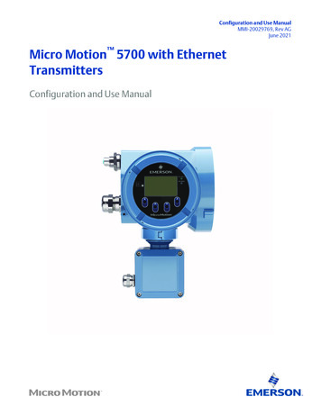
Micro Motion 5700 with Ethernet Transmitters: Configuration and Use Manual Hazardous area installation — see the approval documentation shipped with the transmitter, or download the appropriate documentation Integration Guide Before you begin MMI-20029770 March 2022.
