Transcription
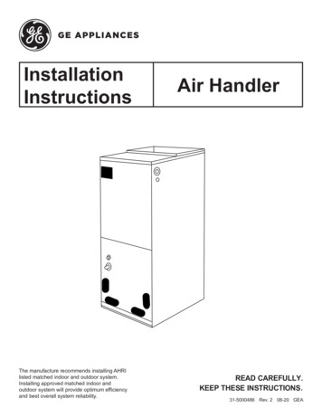
InstallationInstructionsThe manufacture recommends installing AHRIlisted matched indoor and outdoor system.Installing approved matched indoor andoutdoor system will provide optimum efficiencyand best overall system reliability.Air HandlerREAD CAREFULLY.KEEP THESE INSTRUCTIONS.31-5000486 Rev. 2 08-20 GEA
Table of ContentsSAFETY INFORMATION. . . . . . . . . . . . . . . . . . . . . . . . . . . . . . . . . . . . . . . . . . . . . . . . . . . . . . . . . . . . . . . . . . . . . . . . . 4OVERVIEW. . . . . . . . . . . . . . . . . . . . . . . . . . . . . . . . . . . . . . . . . . . . . . . . . . . . . . . . . . . . . . . . . . . . . . . . . . . . . . . . . . . 6ACCESSORIES. . . . . . . . . . . . . . . . . . . . . . . . . . . . . . . . . . . . . . . . . . . . . . . . . . . . . . . . . . . . . . . . . . . . . . . . . . . . . . . .6REQUIRED TOOLS FOR INSTALLATION. . . . . . . . . . . . . . . . . . . . . . . . . . . . . . . . . . . . . . . . . . . . . . . . . . . . . . . . . . . 7UNIT DIMENSIONS . . . . . . . . . . . . . . . . . . . . . . . . . . . . . . . . . . . . . . . . . . . . . . . . . . . . . . . . . . . . . . . . . . . . . . . . . . . . 8MAIN PARTS . . . . . . . . . . . . . . . . . . . . . . . . . . . . . . . . . . . . . . . . . . . . . . . . . . . . . . . . . . . . . . . . . . . . . . . . . . . . . . . . . 9INSTALLATION INSTRUCTIONS. . . . . . . . . . . . . . . . . . . . . . . . . . . . . . . . . . . . . . . . . . . . . . . . . . . . . . . . . . . . . . . . . 10CONVENTIONAL LINE SET INSTALLATION. . . . . . . . . . . . . . . . . . . . . . . . . . . . . . . . . . . . . . . . . . . . . . . . . . . . . . . . 11REFRIGERANT LINE INSTALLATION. . . . . . . . . . . . . . . . . . . . . . . . . . . . . . . . . . . . . . . . . . . . . . . . . . . . . . . . . . . . . 11INSTALL CONDENSATE DRAIN . . . . . . . . . . . . . . . . . . . . . . . . . . . . . . . . . . . . . . . . . . . . . . . . . . . . . . . . . . . . . . . . . 12ELECTRICAL REQUIREMENTS . . . . . . . . . . . . . . . . . . . . . . . . . . . . . . . . . . . . . . . . . . . . . . . . . . . . . . . . . . . . . . . . . 13DUCT SYSTEM. . . . . . . . . . . . . . . . . . . . . . . . . . . . . . . . . . . . . . . . . . . . . . . . . . . . . . . . . . . . . . . . . . . . . . . . . . . . . . . 13HEATER KIT. . . . . . . . . . . . . . . . . . . . . . . . . . . . . . . . . . . . . . . . . . . . . . . . . . . . . . . . . . . . . . . . . . . . . . . . . . . . . . . . . 14ELECTRICAL CONNECTIONS . . . . . . . . . . . . . . . . . . . . . . . . . . . . . . . . . . . . . . . . . . . . . . . . . . . . . . . . . . . . . . . . . . 14THERMAL EXPANSION VALVE. . . . . . . . . . . . . . . . . . . . . . . . . . . . . . . . . . . . . . . . . . . . . . . . . . . . . . . . . . . . . . . . . . 15THERMOSTAT CONNECTION. . . . . . . . . . . . . . . . . . . . . . . . . . . . . . . . . . . . . . . . . . . . . . . . . . . . . . . . . . . . . . . . . . . 16AIR FLOW ADJUSTMENT INSTRUCTIONS FOR CONNECT SERIES. . . . . . . . . . . . . . . . . . . . . . . . . . . . . . . . . . . . 18FINAL CHECK. . . . . . . . . . . . . . . . . . . . . . . . . . . . . . . . . . . . . . . . . . . . . . . . . . . . . . . . . . . . . . . . . . . . . . . . . . . . . . . . 19TROUBLESHOOTING . . . . . . . . . . . . . . . . . . . . . . . . . . . . . . . . . . . . . . . . . . . . . . . . . . . . . . . . . . . . . . . . . . . . . . . . . 19LIMITED WARRANTY. . . . . . . . . . . . . . . . . . . . . . . . . . . . . . . . . . . . . . . . . . . . . . . . . . . . . . . . . . . . . . . . . . . . . . . . . . 21Record KeepingThank you for purchase this product from GE Appliances, a Haiercompany. This installation manual will help you to get the bestperformance.Model numberFor future reference, record the model and serial number located onthe label on the side of your air conditioner, and the date of purchase.Serial numberStaple your proof of purchase to this manual to aid in obtainingwarranty service if needed.Date of purchaseTo register your new air handler, go n and input themodel/serial number information on this page. To receive a 10-yearcompressor and parts warranty, registration is required within 60days of installation.31-5000486 Rev. 23
IMPORTANT SAFETY INFORMATIONREAD ALL INSTRUCTIONS BEFORE USING THE SYSTEMWARNING For your safety, the information in this manual must be followed to minimize the risk of fire,electric shock, or personal injury. Use this equipment only for its intended purpose asdescribed in this manual. T his air handler must be properly installed inaccordance with these instructions before it is used. A ll wiring should be rated for the amperage value listedon the rating plate. Use only copper wiring. A ll electrical work must be completed by a qualifiedelectrician and completed in accordance with local andnational building codes. A ny servicing must be performed by a qualifiedindividual.For any service which requires entry into therefrigerant sealed system, Federal regulationsrequire that the work is performed by a technicianhaving a Class II or Universal certification. A ll air conditioners contain refrigerants, which underfederal law must be removed prior to product disposal.If you are disposing of an old product with refrigerants,check with the company handling disposal. R -410A systems require that contractors and techniciansuse tools, equipment and safety standards approvedfor use with this refrigerant. DO NOT use equipmentcertified for R22 refrigerant only.WARNING RISK OF ELECTRIC SHOCK. Could cause injury or death. A n adequate ground is essential before connecting thepower supply. D isconnect all connected electric power supplies beforeinstallation or service. R epair or replace immediately all electrical wiring thathas become frayed or otherwise damaged. Do not usewiring that shows cracks or abrasion damage along itslength or at either end.WARNING RISK OF FIRE. Could cause injury or death. D o not store or use combustible materials, gasoline or other flammable vapors or liquids in the vicinity of this or anyother appliance.WARNINGThis unit is not intended for use by persons (includingchildren) with reduced physical, sensory or mentalcapabilities, or lack of experience and knowledge.The rated power supply of this product is 208/230VAC/60hz/1PH. Verify the voltage is within the 187 253range before turning the equipment on.To avoid danger of suffocation, keep the plastic bag orthin film used as the packaging material away from youngchildren.Supply power to the air handler should be from adedicated circuit that meets branch circuit ampacityrequirements.Be sure not to allow foreign materials to enter therefrigerant piping. Seal the ends of refrigerant pipingbefore storage.Use a special branch circuit breaker and disconnectswitch matched to the power circuit capacity of the airhandler. Install in accordance with national and localcode.For installation purposes, be sure to use the partssupplied by the manufacturer or other prescribed parts.The use of non-prescribed parts can cause seriousaccidents such as the unit falling, water leakage, electricshock, or fire.431-5000486 Rev. 2
IMPORTANT SAFETY INFORMATIONREAD ALL INSTRUCTIONS BEFORE USING THE SYSTEMCAUTIONIt is highly recommended that you do not open or closethe stop valves when the outdoor temperature is below-5 F (-21 C), as this may cause refrigerant leakage.Do not touch the fins of the coil. Touching the coil finscould result in damage to the fins or personal injury.Ensure the power circuit capacity is adequate for all loadsconnected to the electrical service panel. Increase theconductor and panel capacity if the total electrical loadsexceed the power source capacity.Contact the power utility if the power provided is belowequipment rating plate requirements.Be sure to install a breaker of the specified capacity.Refer to local requirements regarding type and kind ofbreaker, power wiring, and control cable.Regulation of cables and breaker differs from eachlocality. Be aware of these regulations prior to installtion.Do not use existing refrigerant lines.Use refrigerant tubing that is clean and free of anycontamination which may cause damage to the system,including sulfur, copper oxide, dust, metal chips, powder,oil, or water.Avoid coupling lines whenever possible. Use a continuouslength of copper tubing, as oxides formed during improperbrazing techniques can damage the equipment.Do not use copper pipes that have a collapsed,deformed, or discolored portion (especially on the interiorsurface). Otherwise, the expansion valve or capillary tubemay become blocked with contaminants.Improper line sizing will degrade performance. Peakpressure of R410A is much higher than R22. Use ACRcopper tubing with adequate wall thickness.Use a tubing bender to change piping direction. Makesure the radius of the bend is no less than 4”.If the pipe is bent repeatedly at the same place, it willbreak.SAVE THESE INSTRUCTIONSFOR MORE HELP, VISIT HAIERAPPLIANCES.COM OR CALL THE CONSUMER HELP LINE AT 877-337-3639.BEFORE YOU BEGINRead these instructions completely and carefully.IMPORTANT – Save these instructions for local inspector’s use.IMPORTANT – Observe all governing codes and ordinances. Note to Installer – Be sure to leave these instructionswith the owner to use for future reference. Note to Owner – Keep these instructions for futurereference. Skill level – A licensed certified technician (to handlerefrigerant R-410A, recovery, etc.) and a qualifiedelectrician are required for equipment and service of thisair handler system. Use team lift for installation of this product. Proper installation is the responsibility of the installer. Product failure due to improper installation is not coveredunder the limited warranty. For personal safety, this system must be properlygrounded. Protective devices (fuses or circuit breakers) acceptablefor installation are specified on the nameplate of each unit. Piping or wiring within walls must be protected per local code.31-5000486 Rev. 2CAUTION Aluminum electrical wiring may present specialproblems - consult a qualified electrician. When the unit is in the STOP position, there is stillvoltage to the electrical controls.OUTDOOR REQUIUREMENTSThere is a matching air handler and must be used withthe outdoor units as rated by AHRI.The outdoor sections are manufactured with aninterchangeable refrigerant metering device for optimumrefrigerant control and system performance. The AHRIrating may require the metering device be changed, insome cases, to meet the rated performance.5
OverviewIt is the responsibility of the installer to ensure allinstallation aspects of this product adhere to national,state, and local codes.Every possible system difference or work site abnormalitycannot be addressed in this manual. If questions arise, itis the obligation of the installer to contact the distributor orsupplier of this product for assistance.To ensure proper performance, the duct system pressuredrop should never exceed the static pressure capacity ofthe blower.Only use and apply accessory heater components thatare approved in this manual.All work should be performed by persons trained,experienced, and licensed in the mechanical andelectrical fields.The manufacturer will not be responsible for equipmentthat is under-performing due to a failure to follow theinstructions in this manual or best industry practices.The manufacturer has the right to revise this manualwithout notice.1. No person should operate, maintain, or service thisequipment unless suitably trained by an industryprofessional.2. Disconnect unit from the power supply if it not to be usedfor an extended period.3. Be certain that you have selected the proper model for theoperating load. Improper selection may impact operatingperformance.4. Please do not disassemble the unit without propertraining. This equipment has undergone strict inspectionand operational testing at the factory.5. For technical assistance, please contact GE Appliancestechnical support6. If the product is malfunctioning and/or is inoperable, Owner’splease contact GE Appliances technical support. Providethe following information:a. Product Nameplate data (model number, cooling / heatingcapacity, product serial number, factory date)b. Nature of Malfunction (specify the circumstances beforeand after the error occurred)7. All illustrations and information in the instruction manualare for reference only. We retain the right to makenecessary revisions to the product from time to time.8. GE Appliances assumes no responsibility for personalinjury, property loss or equipment damage caused byimproper installation and commissioning, unecessarymaintenance, or failure to follow relevant federal and stateregulations, industry standards, and the requirements ofthis instuction manual.9. G E Appliances will bear no responsibilities for personalinjury or property damage caused by the following:a. Improper use of the applianceb. Altering, maintaining, or operating the product with nonapproved equipment.c. Altering, maintaining, or operating the product outside ofthe guidelines of this manual.d. Defects caused by corrosive gas.e. Defects caused by shipping damage.f. Failure to abide by this instruction manual or governmentregulations.g. Products made by other manufacturersh. Natural disasters, improper installation environment, orforce majeure.ManualAccessoriesPartLooks LikeOwner’sManualOwner’s ManualQuantity1Owner’sManualOptional Liquid Side Stub Kit1To connect the unit with the liquid pipeOptional Gas Side Stub Kit1To connect the unit with the gas pipe631-5000486 Rev. 2
Installation InstructionsRequired Tools for Installation 18-8 thermostat wire 5/8” (16mm), 7/8” (22mm), 1” (25mm) or AdjustableWrench R-410A Refrigerant* Adhesive tape* Conduit cable clamp 1/2”* Copper line set (for size, see table on page 15) #2 phillips screwdriver Drill R-410A flaring tool Hex wrench Hole saw 2 1/4” Insulation* Refrigerant scale Level Manifold gauge set Measuring tape31-5000486 Rev. 2 Micron gauge Mini-split adapter (5/16”F to 1/4”M) Nitrogen* Pipe cutter PVC pipe Razor knife Reamer Saddle clamp (L.S.) w/ screws Sealant, non-expanding (for lineset hole) Soap/water solution* or gas leakage detector Stud finder Torque wrench Vacuum pump Wire strippers All usual and customary HVAC hand and power tools,meters, and testing devices* consumable7
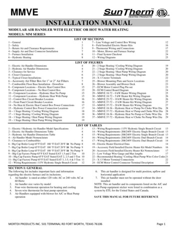
Installation InstructionsUnit (1448)11-5/8(295)20(508)Installation Clearances24” clearance is required for filter, coil, or blower removal and service access.The air handler can be installed in a closet with a false bottom to form a return air plenum or be installed with a returnair plenum under the air handler.831-5000486 Rev. 2
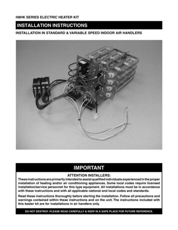
Installation InstructionsMain PartsControl BoxAssemblyBlower WheelFan MotorSecondary Drain PanEvaporatorAssemblyPrimary Drain Pan31-5000486 Rev. 2ModelCooling capacity (ton)Optional electric heater 60ZGDAA5.015ModelMotor @ 230V , ZGDAA13.2ModelFilter SizeUUY24ZGDAAUUY36ZGDAA20” x 20”UUY48ZGDAAUUY60ZGDAA21” x 20”9
Installation InstructionsCAUTIONPrior to installation, turn off all electrical power suppliesintended for use with this equipment.1. Checking Product ReceivedAfter receiving the product, please check for anydamage caused by transportation. Shipping damageis the responsibility of the carrier. Verify the modelnumber, specifications, and accessories are correctprior to installation. The distributor or manufacturerwill not accept claims from dealers for transportationdamage or installation of incorrectly shipped units.The manufacturer assumes no responsibility for theinstallation of incorrectly delivered units.2. Before InstallationCarefully read all instructions for the installation priorto installing. Make sure each step or procedure isunderstood and any special considerations are takeninto account before starting installation. Assemble alltools, hardware and supplies needed to complete theinstallation. Some items may need to be purchasedseparately. Make sure everything needed to install theproduct is on hand before starting.3. Codes and RegulationsThis product is designed and manufactured to complywith national codes. It is installer’s responsibilitiesto install the product in accordance with such codesand/or any prevailing local codes/regulations. Themanufacturer assumes no responsibilities for equipmentinstalled in violation of any codes or regulations.4. Replacement PartsWhen reporting shortages or damages, or orderingrepair parts, give the complete product model and serialnumbers as stamped on the nameplate. Replacementparts are available through your contractor or localdistributor.WARNING T his air handler is designed for indoor installationonly. Do not install it outdoors. W hen installing the air handler, take consideration tominimize the length of refrigerant tubing as much aspossible. W hen installing in an area directly over a finishedceiling (such as an attic), installation of an emergencydrain pan is required directly under the unit. See localand state code for requirements. W hen installing this unit in an area that may becomewet, elevate the unit with a sturdy,non-porous material. Install a protective barrier percode for installations that may be subject to damage,such as a garage. T his air handler is designed for a complete supplyand return duct system. DO NOT operate this productwithout attaching a completed duct system.DO NOT install the air handler in a location above orbelow the outdoor unit that violates the instructionsprovided with the outdoor unit. Service clearance isto take precedence. Allow a minimum of 24” serviceclearance in front of the unit. I f this air handler is to be installed in an enclosedspace containing fossil fuel burning appliances,vehicle exhaust emissions, or other potential carbonmonoxide sources, all code requirements for theseconditions must be strictly followed. Carbon monoxideemissions can be circulated throughout the occupiedspace by the air handler’s duct system, causing deathor serious illness.Typical installation configurations as shownUpflow10Horizontal Left31-5000486 Rev. 2
Installation InstructionsConventional Line Set InstallationPipe SizeModelExternal Diameter (inch)Gas pipeLiquid Proper flaring is essential to achieve an airtight seal.1. Ensure there is enough insulation to protect the entireline set from end to end. Use multiple light passeswhen cutting tubing to the desired length, tighteningthe cutting wheel only until light resistance is felt.Ream both outside and inside, holding tube down tokeep reaming chips from falling into the tube.2. Use the flare nuts from the accessories pouch,located in the indoor unit packaging. Fit the nut onthe tubing to be flared.Flare nutCopper pipe3. Remove the seal over the exposed end, and placethe tube into the R-410A flaring tool.4. Run the tube against the flaring tool pipe stop, andclamp the form on the tube.5. Rotate the handle of the die clockwise until the clutchreleases, then remove the flared tubing from the form.Flare formAPipeA 1/16” (1.6mm)Refrigerant Line InstallationRefrigerant lines must be connected by a licensed,EPA certified refrigerant technician in accordance withestablished procedures.IMPORTANT: Connecting refrigerant lines must be clean,dehydrated, refrigerant-grade copper lines. Air handlercoils should be installed only with specified line sizesfor approved system combinations. Use care with the refrigerant lines during theinstallation process. Sharp bends or possible kinkingin the lines will cause a restriction. Do not remove the caps from the lines or systemconnection points unit connections are ready to becompleted.1. Route the suction and liquid lines from the fittings onthe indoor coil to the fittings on the outdoor unit. Runthe lines in a direct path, avoiding unnecessary turnsand bends.2. Ensure that the suction line is insulated over theentire exposed length and that both suction andliquid lines are not in direct contact with floors, walls,ductwork, floor joists, or other piping.3. Connect the suction and liquid line to the evaporatorcoil.4. To avoid damage; remove the TXV sensing bulbwhile brazing. Relocate rubber grommets away fromthe heat to avoid melting them.5. Braze with an alloy of silver or cooper andphosphorus with a melting point above 1,100 F.NOTE: Do not use soft solder.6. Reinstall the TXV sensing bulb and the rubbergrommets after brazing is finished.7. Make sure the outdoor air conditioning unit has beenput in place according to the Installation Instructionsand is connected to the refrigerant lines.While brazing, purge the system with Nitrogen toprevent contamination. Manufacturer recommendsreattaching and insulating the TXV sensing bulb at a 10or 2 o’clock position on the suction line, outside the coilhousing, no more than one foot from the connection.Evacuate the system to 500 microns to ensure properair and moisture removal (Note: Deep evacuation ortriple evacuation method recommended). Open thesuction service valve slowly and allow the refrigerant tobleed into the system before opening the liquid servicevalve.6. Examine the flare to make sure there are noimperfections on the lip of the flare, and that the backof the flare exactly fits the seat of the flare nut.31-5000486 Rev. 211
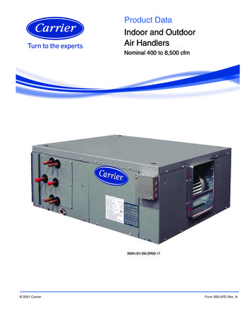
Installation InstructionsThe air handler is provided with 3/4” NPT condensatedrain connections.A field fabricated secondary drain pan with a drainpipe to the outside of the building is required in allinstallations over a finished living space or in any areathat may be damaged by overflow from the main drainpa. In some localities, local codes require secondarydrain pan for any horizontal installations. The secondarydrain pan must have a larger footprint than the airhandler.1. Remove the appropriate panel knockouts for drains.See “Drain Pan Connections” section. You may needto remove the indoor coil assembly from the cabinet.2. Determine the drain connection to be used andnote differences between the primary (green) andsecondary (red) openings. Drain plugs are providedfor all openings; remove and discard the appropriateplugs with 1/2” drive ratchet and verify that remainingplugs are tight (2.5 ft-lbs). Attach drain line to panwith 3/4” make pipe thread PVC fittings. Hand tight isadequate—do not over tighten and do not reduce theline size.3. Secondary drain connections should be connectedto a separate drainage system. Run this drain toa place in compliance with local installation codeswhere is will be secondary drain indicates a pluggedprimary drain.4. Install a 2” trap in the primary drain line as close tothe unit as practical. Make sure the top of the trapis below the connection to the drain pan to allowcomplete drainage of the pan.NOTE: Horizonal runs must also have an anti-siphonair vent (standpipe) installed ahead of the horizontalrun. An extremely long horizontal run may require anoversized drain line to eliminate air trapping.NOTE: Do not operate air handler without a drain trap.The condensate drain is on the negative pressureside of the blower; therefore being pulled through thecondensate line will prevent positive drainage without aproper trap.5. Route the drain line to the outside or to anappropriate drain. Drain lines must be installed sothey do not block serviceaccess to the front of the airhandler. A 24” clearance is required for filter, coil, orblower removal and service access.NOTE: Check local codes before connecting the drainline to an existing drainage system.6. Insulate the drain lines where sweating could causewater damage.Upon completeion of installation, it is the responsibilityof the installer to ensure the drain pan(s) is capturingall condensate, and all condensate is draining properlyand not getting into the duct/system.12Install Condensate Drain (cont.)1. P our several quarts of water into the drain pan,enough to fill drain trap and line.2. Check to make sure the drain pan is drainingcompletely, no leaks are found in drain line fittings,and water is draining from the end o the primarydrain pan.3. Correct any leaks found.Drain Line and Vent TeeClean OutPress in(DO NOT GLUE)2” Min.Drain PanDrain Line3/4” MPT ConnectorReducing Tee with1” Slip Hex PlugVent must extend a minimum of 2”above the drain panVent“T”Install Condensate Drain2” Min.Pitch horizontaldrain linesdownward 1” per 10'Insulate pipe as needed31-5000486 Rev. 2
Installation InstructionsElectrical RequirementsModelPower SupplyRecommended breakersize V-1Ph-60Hz15Wiring ConnectionsUsing 18 Gauge Solid Core Copper Wire1. Cut back the insulation 1” from the end of the wire.2. Remove the screw from the terminal block, and wrapthe wire around the screw.3. Return the screw and wire to the terminal block andtighten securely.1. High and low voltage wires should be led throughdifferent rubber rings of the electric box cover.2. To avoid communication errors, maintain as muchseparation as possible between the power and controlwiring.3. High and low voltage wires should be securedseparately. Secure the former ones with large clampsand the latter ones with small clamps.4. Use screws to tighten high and low voltage wiring onthe terminal board. Improper connection may create afire hazard.5. Ground the units by connecting the ground wire.6. All wiring must comply with local and national code.1” (25mm)Control wiring” to “Electric wiringScrew withSpecial FastenerRoundTerminalJacket / InsulationStranded Wire1. Cut back the insulation 3/8” from the end of the wire.2. Make sure the round or forked terminal connector israted for the amperage of the unit being installed.3. Use a crimping tool only to fasten the connector to thewire.4. Return the screw and connector to the terminal blockand tighten securely.3/8” (10mm)SolderlessTerminal31-5000486 Rev. 2TerminalBoardWireDuct SystemCAUTION1. Ensure that the power supply is disconnected prior toinstalling the heater kit.2. A means of strain relief and conductor protection mustbe provided at the supply wire entrance into cabinet.3. Only use copper conductors.4. Installation must follow The National Electrical Codeand other applicable codes.5. If this appliance is installed in an enclosed area, suchas a garage or utility room with any carbon monoxideproducing appliance, ensure that area is properlyventilated to the outside.13
Installation InstructionsElectrical ConnectionsHeater Kit1. Refer to the table for the appropriate heater kit.2. Check for any physical damage; do not install adamaged heater kit.3. Remove the upper access panel from the air handler.4. Remove cover plate from air handler.5. Slide the heater kit into the slot and secure elementplate with previously removed screws.Connect to 8kw heater Circuit BreakerAir Handler Supply VoltageWire ConnectionsField SupplyGround Wires208/230 VoltField Supply Wires6. Insert power leads into the circuit breaker lugs orstripped red and black wires (for heater kit withoutcircuit breaker) and tighten.7. Connect ground wire to ground lug.8. Knock off appropriate area of the plastic circuitbreaker cover on the access panel of the air handler.Knock off the holes according to the actual installationnumber and positions of circuit breakers. If circuitbreaker is not installed, do not knock off the holes,otherwise there maybe has electric shock occur.9. Replace access panel and check operation.Connect to 15kw heater Circuit BreakerAir Handler Supply VoltageWire ConnectionsField SupplyGround Wires10. Finalize power and control wiring.208/230 VoltField Supply WiresCover PlateBoltHeater KitConnect to Terminal BlockAir Handler Supply Voltage Wire ConnectionsCircuit BreakerFig 2.9Field SupplyGround WiresL2208/230 VoltField Supply WiresL1Kit #DescriptionATTENTION: If it is new air handler and it is the firsttime install heat, make sure the L1/L2 wire to heaterbreaker, then wire the ground wire. Use proper wiresize as specified in this manual for 8K and 15 K heaterassemblies.If there is no heat kit to install, please make sure wire toterminal block.UAZEH08A 8kW Heater with 45A breakerUAZEH15A 15kW Heater with 30A and 60Abreakers1431-5000486 Rev. 2
Installation InstructionsThermal Expansion Valve (TXV)Factory Installed Expansion Valves: Sensing bulbs arefactory installed and clamped to the suction line. Foroptimum performance, reattach and insulate the bulbat a 10 or 2 o’clock position outside of the cabinet tothe main suction line no more than one foot from thesuction line connection. If necessary, the bulb can beinstalled on a vertical suction line. In this instance, thebulb must be placed before any trap, with the bulb’scapillary tube facing upward.Thermal Expansion Valve (Letter A)NOTE: Some models are equipped with thermo expansionvalve and do not require any orifice change.NOTE: The coil comes pre-charged with refrigerantR410A. The coil must be evacuated if the TXV valve ischanged.31-5000486 Rev. 215
Installation InstructionsThermostat Connections(Only for air handler without electric heater)See NoteGCB1XT1L1L2L1Power L2GThermostatXT2YBW1RCGYBW1RCGCB18kw Heat KitX1X1Note:1. Please refer to the Instruction Manual to checkwhether the unit can connect to the engineerigelectric heating.2. When the unit doesn't connect to the engineeringelectric heating, connect the engineering powersupply to the L1 and L2 of wiring board.3. When the unit connects to the engineering electyricheating, connect the engineering power supply tothe brea
The rated power supply of this product is 208/230 . VAC/60hz/1PH. Verify the voltage is within the 187 253 range before turning the equipment on. Supply power to the air handler should be from a dedicated circuit that meets branch circuit ampacity . requirements. Use a special branch circuit breaker and disconnect