Transcription
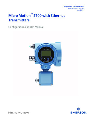
Configuration and Use ManualMMI-20029769, Rev AGJune 2021Micro Motion 5700 with EthernetTransmittersConfiguration and Use Manual
Safety messagesSafety messages are provided throughout this manual to protect personnel and equipment. Read each safety message carefullybefore proceeding to the next step.Safety and approval informationThis Micro Motion product complies with all applicable European directives when properly installed in accordance with theinstructions in this manual. Refer to the EU declaration of conformity for directives that apply to this product. The following areavailable: the EU declaration of conformity, with all applicable European directives, and the complete ATEX Installation Drawingsand Instructions. In addition the IECEx Installation Instructions for installations outside of the European Union and the CSAInstallation Instructions for installations in North America are available on the internet at www.emerson.com or through your localMicro Motion support center.Information affixed to equipment that complies with the Pressure Equipment Directive, can be found on the internet atwww.emerson.com. For hazardous installations in Europe, refer to standard EN 60079-14 if national standards do not apply.Other informationFull product specifications can be found in the product data sheet. Troubleshooting information can be found in the configurationmanual. Product data sheets and manuals are available from the Micro Motion web site at www.emerson.com.Return policyFollow Micro Motion procedures when returning equipment. These procedures ensure legal compliance with governmenttransportation agencies and help provide a safe working environment for Micro Motion employees. Micro Motion will not acceptyour returned equipment if you fail to follow Micro Motion procedures.Return procedures and forms are available on our web support site at www.emerson.com, or by phoning the Micro MotionCustomer Service department.Emerson Flow customer serviceEmail: Worldwide: flow.support@emerson.com Asia-Pacific: APflow.support@emerson.comTelephone:2North and South AmericaEurope and Middle EastAsia PacificUnited States800-522-6277U.K. and Ireland0870 240 1978Australia800 158 727Canada 1 303-527-5200The Netherlands 31 (0) 70 4136666New Zealand099 128 804Mexico 52 55 5809 5010France 33 (0) 800 917901India800 440 1468Argentina 54 11 4809 2700Germany0800 182 5347Pakistan888 550 2682Brazil 55 15 3413 8000Italy 39 8008 77334China 86 21 2892 9000Chile 56 2 2928 4800Central & Eastern 41 (0) 41 7686111Japan 81 3 5769 6803Peru 51 15190130Russia/CIS 7 495 995 9559South Korea 82 2 3438 4600Egypt0800 000 0015Singapore 65 6 777 8211Oman800 70101Thailand001 800 441 6426Qatar431 0044Malaysia800 814 008Kuwait663 299 01South Africa800 991 390Saudi Arabia800 844 9564UAE800 0444 0684
Configuration and Use ManualMMI-20029769ContentsJune 2021ContentsChapter 1Before you begin. 71.1 About this manual. 71.2 Hazard messages. 71.3 Related documents.81.4 Communication methods. 8Chapter 2Quick start. 92.1 Power up the transmitter. 92.2 Check meter status. 92.3 Commissioning wizards. 102.4 Make a startup connection to the transmitter.102.5 Set the transmitter clock.112.6 View the licensed features. 112.7 Set informational parameters. 122.8 Characterize the meter (if required).122.9 Verify mass flow measurement.152.10 Verify the zero. 15Chapter 3Introduction to configuration and commissioning.173.1 Security and write protection.173.2 Work with configuration files. 22Chapter 4Configure process measurement.294.1 Configure Sensor Flow Direction Arrow . 294.2 Configure mass flow measurement. 304.3 Configure volume flow measurement for liquid applications. 354.4 Configure Gas Standard Volume (GSV) flow measurement. 394.5 Configure density measurement.444.6 Configure temperature measurement. 464.7 Configure Pressure Measurement Unit .484.8 Configure Velocity Measurement Unit . 49Chapter 5Configure process measurement applications. 515.1 Set up the API Referral application . 515.2 Set up concentration measurement.615.3 Configure the batching application.77Chapter 6Configure advanced options for process measurement. 836.1 Configure Response Time . 836.2 Detect and report two-phase flow. 836.3 Configure Flow Rate Switch .85Configuration and Use Manual3
ContentsJune 2021Configuration and Use ManualMMI-200297696.4 Configure events. 866.5 Configure totalizers and inventories. 886.6 Configure logging for totalizers and inventories.916.7 Configure Process Variable Fault Action . 92Chapter 7Configure device options and preferences. 977.1 Configure the transmitter display. 977.2 Configure the transmitter's response to alerts. 1037.3 Control button sensitivity on the display.111Chapter 8Integrate the meter with the control system. 1138.1 Channel configuration. 1138.2 Configure Ethernet Channel A and Channel B.1138.3 Configure I/O Channel C. 1138.4 Configure an mA Output.1148.5 Configure a Frequency Output.1228.6 Configure a Discrete Output. 1278.7 Configure a Discrete Input. 130Chapter 9Chapter 10Set the Ethernet protocol. 133Configure, setup, and use a printer for tickets.13510.1 TM-T88VI printer limitations.13510.2 Set up the printer.13510.3 Reset the interface settings. 13810.4 Configure the printer and print tickets. 13910.5 Configure a Discrete Input or discrete event. 14010.6 Ticket types. 140Chapter 11Complete the configuration. 14511.1 Test or tune the system using sensor simulation. 14511.2 Enable or disable software write-protection.146Chapter 12Transmitter operation.14912.1 View process and diagnostic variables. 14912.2 View and acknowledge status alerts. 15012.3 Read totalizer and inventory values.15112.4 Start, stop, and reset totalizers and inventories. 152Chapter 13Operation using the batcher.15513.1 Run a batch.15513.2 Perform AOC calibration. 158Chapter 14Measurement support.16114.1 Use Smart Meter Verification. 16114.2 Advanced Phase Measurement. 16814.3 Piecewise linearization (PWL) for calibrating gas meters. 1694Micro Motion 5700 with Ethernet Transmitters
Configuration and Use ManualMMI-20029769ContentsJune 202114.4 Zero the meter. 16914.5 Set up pressure compensation.17214.6 Validate the meter.17514.7 Perform a (standard) D1 and D2 density calibration. 17714.8 Adjust concentration measurement with Trim Offset .18014.9 Adjust concentration measurement with Trim Slope and Trim Offset . 180Chapter 15Maintenance. 18315.1 Install a new transmitter license.18315.2 Upgrade the transmitter firmware. 18415.3 Reboot the transmitter. 18515.4 Battery replacement. 186Chapter 16Log files, history files, and service files.18716.1 Generate history files. 18716.2 Generate service files.193Chapter 17Troubleshooting. 19917.1 Status LED and device status.19917.2 Network status LED.19917.3 API Referral troubleshooting.20017.4 Batch troubleshooting. 20017.5 Concentration measurement troubleshooting. 20217.6 Alert when connecting a core processor to a remote 5700 transmitter. 20317.7 Density measurement troubleshooting. 20417.8 Discrete Input troubleshooting.20617.9 Discrete Output troubleshooting.20617.10 Flow measurement troubleshooting.20717.11 Frequency Output troubleshooting. 21017.12 mA Output troubleshooting. 21217.13 Status alerts, causes, and recommendations. 21517.14 Perform a core processor resistance test.23417.15 Check the cutoffs.23617.16 Check the direction parameters.23617.17 Check the drive gain. 23617.18 Check for internal electrical problems.23717.19 Check Frequency Output Fault Action . 23817.20 Check the scaling of the Frequency Output.23817.21 Check grounding. 23817.22 Perform loop tests. 23817.23 Check Lower Range Value and Upper Range Value .24417.24 Check mA Output Fault Action .24517.25 Trim mA Output. 245Configuration and Use Manual5
ContentsJune 2021Configuration and Use ManualMMI-2002976917.26 Check the pickoff voltage. 24617.27 Check power supply wiring. 24617.28 Check for radio frequency interference (RFI). 24717.29 Check sensor-to-transmitter wiring. 24817.30 Using sensor simulation for troubleshooting. 24817.31 Check the printing. 24917.32 Check for two-phase flow (slug flow). 24917.33 Check the sensor coils.249Appendix AUsing the transmitter display. 253A.1 Components of the transmitter display. 253A.2 Access and use the display menus. 255Appendix BUsing ProLink III with the transmitter. 259B.1 Basic information about ProLink III . 259B.2 Connect with ProLink III .260Appendix CUsing a web browser to configure the transmitter.263C.1 Recommended web browsers. 263C.2 Configuring transmitter and PC Ethernet settings.263C.3 Log in with a web browser using a secure connection. 264C.4 Log in with a web browser using an unsecure connection. 266C.5 Change Ethernet login passwords.267 C.6 Import the SSL Certificate into Microsoft Windows . 268C.7 Private key file. 269C.8 Import from a Certificate Authority. 269Appendix DConcentration measurement matrices, derived variables, and process variables. 271D.1 Standard matrices for the concentration measurement application. 271D.2 Derived variables and calculated process variables. 272Appendix EEnvironmental compliance.275E.1 RoHS and WEEE.275Appendix FExample tickets.276F.1 Print examples. 2766Micro Motion 5700 with Ethernet Transmitters
Configuration and Use ManualMMI-20029769Before you beginJune 20211 Before you begin1.1 About this manualThis manual helps you configure, commission, use, maintain, and troubleshoot Micro Motion 5700transmitters with Ethernet.ImportantThis manual assumes that: The transmitter has been installed correctly and completely according to the instructions in thetransmitter installation manual Users understand basic transmitter and sensor installation, configuration, and maintenance concepts andprocedures1.2 Hazard messagesThis document uses the following criteria for hazard messages based on ANSI standards Z535.6-2011(R2017).DANGERSerious injury or death will occur if a hazardous situation is not avoided.WARNINGSerious injury or death could occur if a hazardous situation is not avoided.CAUTIONMinor or moderate injury will or could occur if a hazardous situation is not avoided.NOTICEData loss, property damage, hardware damage, or software damage can occur if a situation is not avoided.There is no credible risk of physical injury.Physical accessNOTICEUnauthorized personnel can potentially cause significant damage and/or misconfiguration of end users'equipment. Protect against all intentional or unintentional unauthorized use.Physical security is an important part of any security program and fundamental to protecting your system.Restrict physical access to protect users' assets. This is true for all systems used within the facility.Configuration and Use Manual7
Before you beginJune 2021Configuration and Use ManualMMI-200297691.3 Related documentsYou can find all product documentation on the product documentation DVD shipped with the product or atwww.emerson.com.See any of the following documents for more information: Micro Motion 5700 Product Data Sheet Micro Motion 5700 with Ethernet Transmitters: Installation Manual Micro Motion Ethernet PROFINET Siemens Integration Guide Micro Motion 5700 Transmitters Ethernet Rockwell RSLogix Integration Guide Replacing the Junction Box for the 4200 Transmitter and the 5700 Transmitter Replacing the Sensor Cable for the 4200 Transmitter and the 5700 Transmitter Sensor installation manual1.4 Communication methodsYou can use several different communications methods to interface with the transmitter. You may usedifferent methods in different locations or for different tasks.InterfaceToolDisplayInfrared-sensitive buttonsUniversal Service PortProLink IIIEthernet portsWeb browser (http) EtherNet/IP Modbus TCP PROFINETFor information about how to use the communication tools, see the appendices in this manual.8Micro Motion 5700 with Ethernet Transmitters
Configuration and Use ManualMMI-20029769Quick startJune 20212 Quick start2.1 Power up the transmitterThe transmitter must be powered up for all configuration and commissioning tasks, or for processmeasurement.Procedure1. Follow appropriate procedures to ensure that a new device on the network does not interfere withexisting measurement and control loops.2. Verify that the cables are connected to the transmitter as described in the installation manual.3. Verify that all transmitter and sensor covers and seals are closed.WARNINGTo prevent ignition of flammable or combustible atmospheres, ensure that all covers and seals aretightly closed. For hazardous area installations, applying power while housing covers are removed orloose can cause an explosion resulting in injury or death.4. Turn on the electrical power at the power supply.PostrequisitesAlthough the sensor is ready to receive process fluid shortly after power-up, the electronics can take up to10 minutes to reach thermal equilibrium. Therefore, if this is the initial startup, or if power has been off longenough to allow components to reach ambient temperature, allow the electronics to warm up forapproximately 10 minutes before relying on process measurements. During this warm-up period, you mayobserve minor measurement instability or inaccuracy.2.2 Check meter statusCheck the meter for any error conditions that require user action or that affect measurement accuracy.Procedure1. Wait approximately 10 seconds for the power-up sequence to complete.Immediately after power-up, the transmitter runs through diagnostic routines and checks for errorconditions. During the power-up sequence, the Transmitter Initializing alert is active. Thisalert should clear automatically when the power-up sequence is complete.2. Check the status LED on the transmitter.Table 2-1: Status LED and device statusStatus LED conditionDevice statusSolid greenNo alerts are active.Solid yellowOne or more alerts are active with Alert Severity Out of Specification,Maintenance Required, or Function Check.Configuration and Use Manual9
Quick startJune 2021Configuration and Use ManualMMI-20029769Table 2-1: Status LED and device status (continued)Status LED conditionDevice statusSolid redOne or more alerts are active with Alert Severity Failure.Flashing yellow (1 Hz)The Function Check in Progress alert is active.Table 2-2: Network status LED and Ethernet network connection statusNetwork status LED conditionNetwork statusFlashing greenNo connections made with primary protocol host.Solid greenConnection made with primary protocol host.Flashing redConnection from primary protocol host has timed out.Solid redAddress Conflict Detection (ACD) algorithm has detected a duplicate IPaddress.2.3 Commissioning wizardsThe transmitter menu includes a Guided Setup to help you move quickly through the most commonconfiguration parameters. ProLink III also provides a commissioning wizard.By default, when the transmitter starts up, the Guided Setup menu is offered. You can choose to use it or not.You can also choose whether or not Guided Setup is displayed automatically. To enter Guided Setup upon transmitter startup, choose Yes at the prompt. To enter Guided Setup after transmitter startup, choose Menu Startup Tasks. To control the automatic display of Guided Setup, choose Menu Configuration Guided Setup.For information on the ProLink III commissioning wizard, see the Micro Motion ProLink III with ProcessVizSoftware User Manual.As the commissioning wizards are self guided, they are not documented in detail.2.4 Make a startup connection to the transmitterFor all configuration tools except the display, you must have an active connection to the transmitter toconfigure the transmitter.ProcedureIdentify the connection type to use, and follow the instructions for that connection type in the appropriateappendix.Communications toolConnection type to useInstructionsProLink IIIService portUsing ProLink III with the transmitterWeb browserEthernetUsing a web browser to configure thetransmitter10Micro Motion 5700 with Ethernet Transmitters
Configuration and Use ManualMMI-20029769Quick startJune 20212.5 Set the transmitter clockDisplayMenu Configuration Time/Date/TagProLink IIIDevice Tools Configuration Transmitter ClockWeb browserConfiguration Time/Date/TagThe transmitter clock provides timestamp data for alerts, service logs, history logs, and all other timers anddates in the system. You can set the clock for your local time or for any standard time you want to use.TipYou may find it convenient to set all of your transmitter clocks to the same time, even if the transmitters arein different time zones.Procedure1. Select the time zone that you want to use.2. If you need a custom time zone, select Special Time Zone and enter your time zone as a differencefrom UTC (Coordinated Universal Time).3. Set the time appropriately for the selected time zone.TipThe transmitter does not adjust for Daylight Savings Time. If you observe Daylight Savings Time, youmust reset the transmitter clock manually.4. Set the month, day, and year.The transmitter tracks the year and automatically adds a day for leap years.2.6 View the licensed featuresDisplayMenu About Licenses Licensed FeaturesProLink IIIDevice Tools Device Infor
Micro Motion 5700 with Ethernet Transmitters Configuration and Use Manual. Safety messages . This Micro Motion product complies with all applicable European directives when properly installed in accordance with the instructions in this manual. Refer to the EU declaration of conformity for directives that apply to this product. The .

