Transcription
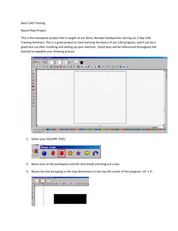
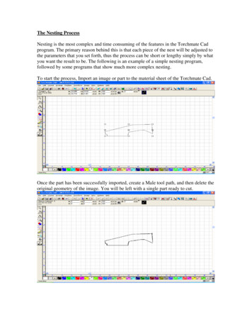
The Nesting ProcessNesting is the most complex and time consuming of the features in the Torchmate Cadprogram. The primary reason behind this is that each piece of the nest will be adjusted tothe parameters that you set forth, thus the process can be short or lengthy simply by whatyou want the result to be. The following is an example of a simple nesting program,followed by some programs that show much more complex nesting.To start the process, Import an image or part to the material sheet of the Torchmate Cad.Once the part has been successfully imported, create a Male tool path, and then delete theoriginal geometry of the image. You will be left with a single part ready to cut.
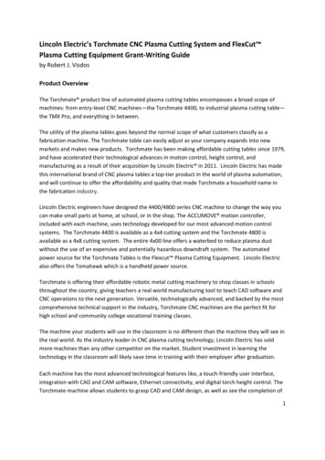
The next process will be to create multiple images of your part. To do this, you may useone of two methods, the Array, or the Badges tools. Each tool will create multipleimages, although they each have different parameters for making the multiple parts. Wewill discuss the Array feature first. With your part selected, open the Layout menu, andscroll down to the Array option. The window below will appear upon choosing theoption.You can now select the method of direction or group of the Array, the Spacing, theRotation, and the Number of Copies to be made. The original part is included in the totalnumber of parts created. Using the parameters shown in the window above, the Arrayyielded the parts shown in the window below.
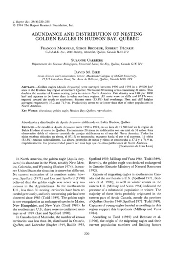
With the Array complete, we can now focus on the Nest. Open the Arrange menu, andscroll to the bottom of the drop-down menu, and select Nesting. Upon choosing theNesting option, the window below will appear. The Nesting widow offers specific toolusage to allow for the Orientation, Rotation, Spacing from edge of the material, Spacingbetween parts, Error Factor, and the use of special formats to make you nest as precise aspossible. Refer to page 2-161 in the User Guide for more information on each of the toolsavailable.Once the OK button is pressed, DO NOT ATTEMPT TO SPEED THE PROCESSALONG, as this may result in the program not responding, or causing your nestingprogram to FAIL. The Program needs time to accurately adjust each part to theparameters set by you, and this process may take a few minutes, so please be patient.When the nesting program is complete, the nested parts will be arranged in the corner anddirection chosen. If you are not happy with the results, you may Undo the last program,and restart using different parameters. Often a change in the amount of rotation will yieldthe better results.
You may also want to try nesting in a different direction to see if this will yield a betteruse of your material. Below the spacing and direction were the only two areas wherechanges were made.The results were only slightly different, but may be closer to what you originallyintended.The Badges feature is similar to the Array feature in that it allows you to make multipleparts, however the way it creates these parts can often yield much more favorable results.The Badges tool also allows you to view the number of parts that you can create on agiven material sheet before actually employing the tool.
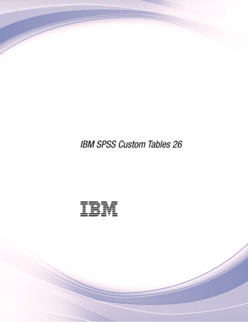
With you original tool path selected, open the Layout menu, and scroll down to theBadges tool towards the bottom of the page. Upon choosing this option, the windowbelow will appear. As you can see you are still able to select the manner in which theparts are arranged vertically and horizontally, however you can not specify rotation or aparticular grouping. Instead, the page preview will show you how many parts can becreated based on a vertical or horizontal direction.The Badge tool yielded the following results, based on the parameter set. The nice thingabout the badges tool is that it will also keep your parts as close together as possible,which is similar to what the Nesting feature performs.
Multiple Part NestingThe next exercise will show two different methods of nesting multiple parts, utilizing theArray, and the Badges tools. To start, import your first DXF file to the material sheet.Place the part on the screen, and then Make Path on the part to be sure all the interiorcomponents are recognized as being a part of the whole object.
Create your Array for the first part.The Array will create the parts in a group, as prescribed by the parameters set in thewindow above.Import your second part, and Make Path on the part after it appears on your screen. If thecolors of the parts change, select them all, and change the back to the Black color byclicking on P1 at the bottom of the Torchmate Cad window.
Perform a similar Array to the first program.Move the second group of parts just to the right of the first.Import the third part, and Make Path on the whole part.
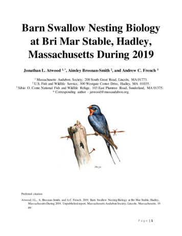
For this example I used the same parameters for all three array programs.Once all three parts have been arrayed, and are displayed on the material sheet, check tobe sure that each part is recognized as an individual, but that it also contains its own innerparts as well. This is necessary to prevent the interior pieces from being removed fromthe part, and nested as a separate part of the whole nesting process. If this step is notcompleted, the resulting nest may separate each interior cut from its original part, andnest it as a completely separate part.For this nest, I used these parameters.
This completed nest yielded the results below. Changes may be necessary to get moreprecise results.You can also use the Badges tool to create each set of your multiple parts, but be sure tomove each group off to the right after its creation, to allow enough room for the nextbadge to be created.
Again, check to be sure that each part is recognized as an individual, as it may separatethe interiors cuts from their own parts when nesting. Once all the sets have been createdusing the Badges tool, Select all, and start the Nesting process.The results of this nest were only slightly different from what the Badge tool yielded, butmodification of your Nesting Parameters may give you better results.Nesting is the one feature of the Torchmate Cad program which we all want to utilize, butone that can also be the most frustrating to learn, and difficult to master. The best thingyou can do to get a better handle of what the nesting program can do for you is to simplyplay with it, be patient with yourself and the program, be willing make mistakes, andlearn from your mistakes, failures, and successes.I hope that this walk-through has allowed you to see a few different ways to creatingmultiple parts, shown you some examples of how to go about nesting these parts into asimplified programs, and how to maximize the usage of your material.
The Nesting Process Nesting is the most complex and time consuming of the features in the Torchmate Cad program. The primary reason behind this is that each piece of the nest will be adjusted to