Transcription
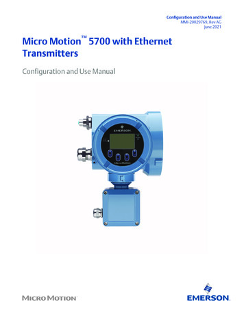
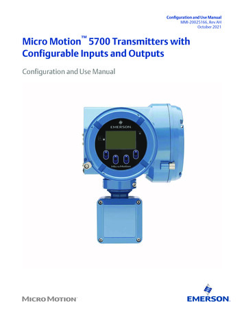
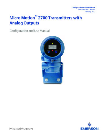
Configuration and Use ManualMMI-20019043, Rev ACFebruary 2022Micro Motion 2700 Transmitters withAnalog OutputsConfiguration and Use Manual
Safety messagesSafety messages are provided throughout this manual to protect personnel and equipment. Read each safety message carefullybefore proceeding to the next step.Safety and approval informationThis Micro Motion product complies with all applicable European directives when properly installed in accordance with theinstructions in this manual. Refer to the EU declaration of conformity for directives that apply to this product. The following areavailable: the EU Declaration of Conformity, with all applicable European directives, and the complete ATEX installation drawingsand instructions. In addition, the IECEx installation instructions for installations outside of the European Union and the CSAinstallation instructions for installations in North America are available at Emerson.com or through your local Micro Motionsupport center.Information affixed to equipment that complies with the Pressure Equipment Directive, can be found at Emerson.com. Forhazardous installations in Europe, refer to standard EN 60079-14 if national standards do not apply.Other informationTroubleshooting information can be found in the Configuration Manual. Product data sheets and manuals are available from theMicro Motion web site at Emerson.com.Return policyFollow Micro Motion procedures when returning equipment. These procedures ensure legal compliance with governmenttransportation agencies and help provide a safe working environment for Micro Motion employees. Micro Motion will not acceptyour returned equipment if you fail to follow Micro Motion procedures.Return procedures and forms are available on our web support site at Emerson.com, or by calling the Micro Motion CustomerService department.2
Configuration and Use ManualMMI-20019043ContentsFebruary 2022ContentsChapter 1Before you begin. 71.1 About this manual. 71.2 Hazard messages. 71.3 Transmitter model code. 71.4 Communications tools and protocols. 81.5 Related documentation. 8Chapter 2Quick start. 112.1 Power up the transmitter. 112.2 Check meter status.112.3 Make a startup connection to the transmitter.122.4 (Optional) Adjust digital communications settings. 132.5 Verify mass flow measurement.132.6 Verify the zero. 13Chapter 3Introduction to configuration and commissioning.173.1 Configuration flowchart.173.2 Default values and ranges. 183.3 Enable access to the off-line menu of the display. 183.4 Disable write-protection on the transmitter configuration.183.5 Set the HART lock. 183.6 Restore the factory configuration. 19Chapter 4Configure process measurement.214.1 Configure mass flow measurement. 214.2 Configure volume flow measurement for liquid applications. 254.3 Configure GSV flow measurement. 304.4 Configure Flow Direction . 354.5 Configure density measurement .404.6 Configure temperature measurement. 444.7 Configure the petroleum measurement application. 464.8 Set up concentration measurement .524.9 Configure pressure compensation. 59Chapter 5Configure device options and preferences. 655.1 Configure the transmitter display. 655.2 Enable or disable operator actions from the display. 695.3 Configure security for the display menus. 705.4 Configure response time parameters.725.5 Configure alert handling. 74Configuration and Use Manual3
ContentsFebruary 2022Configuration and Use ManualMMI-200190435.6 Configure informational parameters.79Chapter 6Integrate the meter with the control system. 836.1 Configure the transmitter channels. 836.2 Configure the mA Output. 836.3 Configure the Frequency Output. 916.4 Configure the Discrete Output.956.5 Configure events. 996.6 Configure digital communications.101Chapter 7Complete the configuration. 1117.1 Test or tune the system using sensor simulation. 1117.2 Back up transmitter configuration. 1137.3 Enable write-protection on the transmitter configuration.113Chapter 8Set up the Weights & Measures application. 1158.1 Weights & Measures application. 1158.2 Set up the Weights & Measures application using ProLink III .116Chapter 9Transmitter operation.1199.1 Record the process variables.1199.2 View process variables. 1199.3 View transmitter status using the status LED. 1219.4 View and acknowledge status alerts. 1229.5 Read totalizer and inventory values.1269.6 Start and stop totalizers and inventories. 1269.7 Reset totalizers. 1279.8 Reset inventories. 129Chapter 10Operate the transmitter with the Weights & Measures application.13110.1 Operate the transmitter when the Weights & Measures application is installed. 13110.2 Switch between secured and unsecured mode. 13610.3 Clear Status Alarm A027: Security Breach. 13710.4 Replacing the core processor in a Weights & Measures installation. 138Chapter 11Measurement support.13911.1 Options for measurement support. 13911.2 Use Smart Meter Verification. 13911.3 Use Production Volume Reconciliation, Transient Mist Remediation, and Transient BubbleRemediation. 14911.4 Piecewise linearization (PWL) for calibrating gas meters. 15011.5 Use the fuel consumption application.15111.6 Zero the meter. 15211.7 Validate the meter.15311.8 Perform a (standard) D1 and D2 density calibration. 15511.9 Perform a D3 and D4 density calibration (T-Series sensors only). 1574Micro Motion 2700 Transmitters with Analog Outputs
Configuration and Use ManualMMI-20019043ContentsFebruary 202211.10 Perform temperature calibration. 160Chapter 12Troubleshooting. 16512.1 Status LED states. 16512.2 Check the cutoffs.16512.3 Check the core processor LED. 16612.4 Perform a 700 core processor resistance test.17012.5 Density measurement problems.17312.6 Check the drive gain. 17412.7 Check for internal electrical problems.17512.8 Check Flow Direction . 17712.9 Flow measurement problems .17812.10 Frequency Output problems.18012.11 Check Frequency Output Fault Action . 18012.12 Check Frequency Output Scaling Method . 18112.13 Check grounding. 18112.14 Locate a device using the HART 7 Squawk feature.18112.15 Check HART Address and mA Output Action.18112.16 Check HART burst mode. 18212.17 Check the HART communication loop. 18212.18 Perform loop tests. 18312.19 Check Lower Range Value and Upper Range Value .18712.20 Milliamp output problems. 18712.21 Check mA Output Fault Action .18912.22 Trim mA Output. 18912.23 Check the pickoff voltage. 19012.24 Check power supply wiring. 19112.25 Check for radio frequency interference (RFI). 19212.26 Using sensor simulation for troubleshooting. 19212.27 Check sensor-to-transmitter wiring. 19312.28 Check for two-phase flow (slug flow). 19312.29 Status alerts, causes, and recommendations. 19412.30 Temperature measurement problems. 213Appendix AUsing the transmitter display. 215A.1 Components of the transmitter interface. 215A.2 Use the optical switches. 215A.3 Access and use the display menu system. 216A.4 Display codes for process variables. 220A.5 Codes and abbreviations used in display menus.221Appendix BUsing ProLink III with the transmitter. 225B.1 Basic information about ProLink III . 225Configuration and Use Manual5
ContentsFebruary 2022Configuration and Use ManualMMI-20019043B.2 Connect with ProLink III .226Appendix CUsing a field communicator with the transmitter. 239C.1 Basic information about field communicators. 239C.2 Connect with a field communicator . 240Appendix DDefault values and ranges. 243D.1 Default values and ranges. 243Appendix ETransmitter components and installation wiring. 249E.1 Installation types.249E.2 Power supply terminals and ground . 251E.3 Input/output (I/O) wiring terminals.252Appendix FNE 53 history.253F.1 NE 53 history.2536Micro Motion 2700 Transmitters with Analog Outputs
Configuration and Use ManualMMI-20019043Before you beginFebruary 20221 Before you begin1.1 About this manualThis manual helps you configure, commission, use, maintain, and troubleshoot Micro Motion 2700transmitters with analog outputs.ImportantThis manual assumes that: The transmitter has been installed correctly and completely according to the instructions in thetransmitter installation manual Users understand basic transmitter and sensor installation, configuration, and maintenance concepts andprocedures1.2 Hazard messagesThis document uses the following criteria for hazard messages based on ANSI standards Z535.6-2011(R2017).DANGERSerious injury or death will occur if a hazardous situation is not avoided.WARNINGSerious injury or death could occur if a hazardous situation is not avoided.CAUTIONMinor or moderate injury will or could occur if a hazardous situation is not avoided.NOTICEData loss, property damage, hardware damage, or software damage can occur if a situation is not avoided.There is no credible risk of physical injury.Physical accessWARNINGUnauthorized personnel can potentially cause significant damage and/or misconfiguration of end users'equipment. Protect against all intentional or unintentional unauthorized use.Physical security is an important part of any security program and fundamental to protecting your system.Restrict physical access to protect users' assets. This is true for all systems used within the facility.1.3 Transmitter model codeYou can verify that this manual pertains to your transmitter by ensuring the model code on the transmittertag matches the format.Example:Configuration and Use Manual7
Before you beginFebruary 2022Configuration and Use ManualMMI-20019043The transmitter has a model number of the following form: 2700(R/I/E/B/C/M/P/H)**A******R4-wire remote-mount with aluminum housingIIntegral mountE4-wire remote mount transmitter with 9-wire remote enhanced core processorB4-wire remote mount transmitter with 9-wire remote core processorC9-wire remote-mount with integral core processor and aluminum housingM 4-wire remote mount with stainless steel housingP9-wire remote mount transmitter with integral core processor and stainless steel housingH4-wire remote mount for connecting to CDM/FDM/FVM metersAAnalog outputs option board1.4 Communications tools and protocolsYou can use several different communications tools and protocols to interface with the transmitter, usedifferent tools in different locations, or use different tools for different tasks.ToolSupported protocolsProLink III HART/RS-485 HART/Bell 202 Modbus/RS-485 Service portField CommunicatorHART/Bell 202For information about how to use the communication tools, see the appendices in this manual.TipYou may be able to use other communications tools, such as AMS Suite: Intelligent Device Manager, or theSmart Wireless THUM Adapter. Use of AMS or the Smart Wireless THUM Adapter is not discussed in thismanual. For more information on the Smart Wireless THUM Adapter, refer to the documentation available atEmerson.com.1.5 Related documentationYou can find all product documentation on the product documentation DVD shipped with the product or atEmerson.com.See any of the following documents for more information: Micro Motion Series 1000 and Series 2000 Transmitters with MVD Technology Product Data Sheet Micro Motion 1700 and 2700 Installation Manual Micro Motion Enhanced Density Application Manual Micro Motion Fuel Consumption Application for Transmitters Installation and Operation Guide8Micro Motion 2700 Transmitters with Analog Outputs
Configuration and Use ManualMMI-20019043Before you beginFebruary 2022 Micro Motion Oil and Gas Production Supplement Modbus Interface Tool Sensor installation manualConfiguration and Use Manual9
Before you beginFebruary 202210Configuration and Use ManualMMI-20019043Micro Motion 2700 Transmitters with Analog Outputs
Configuration and Use ManualMMI-20019043Quick startFebruary 20222 Quick start2.1 Power up the transmitterThe transmitter must be powered up for all configuration and commissioning tasks or for processmeasurement.Procedure1.WARNINGIf the transmitter is in a hazardous area, do not remove the housing cover while the transmitter ispowered up. Failure to follow these instructions can cause an explosion resulting in injury or death.Ensure that all transmitter and sensor covers and seals are closed.2. Turn on the electrical power at the power supply.The transmitter will automatically perform diagnostic routines. The transmitter is self-switching andwill automatically detect the supply voltage. When using DC power, a minimum of 1.5 amps of startupcurrent is required. During this period, Alert 009 is active. The diagnostic routines should complete inapproximately 30 seconds. The status LED will turn green and begin to flash when the startupdiagnostics are complete. If the status LED exhibits different behavior, an alert is active.PostrequisitesAlthough the sensor is ready to receive process fluid shortly after power-up, the electronics can take up toten minutes to reach thermal equilibrium. Therefore, if this is the initial startup, or if power has been off longenough to allow components to reach ambient temperature, allow the electronics to warm up forapproximately ten minutes before relying on process measurements. During this warm-up period, you mayobserve minor measurement instability or inaccuracy.2.2 Check meter statusCheck the meter for any error conditions that require user action or that affect measurement accuracy.Procedure1. Wait approximately 10 seconds for the power-up sequence to complete.Immediately after power-up, the transmitter runs through diagnostic routines and checks for errorconditions. During the power-up sequence, Alert A009 is active. This alert should clear automaticallywhen the power-up sequence is complete.2. Check the status LED on the transmitter.Related informationView and acknowledge status alertsStatus alerts, causes, and recommendationsConfiguration and Use Manual11
Quick startFebruary 2022Configuration and Use ManualMMI-200190432.2.1 Transmitter status reported by LEDLED stateDescriptionRecommendationSolid greenNo alerts are active.Continue with configuration or processmeasurement.Flashing green (ifenabled)Unacknowledged corrected condition (noalert)Continue with configuration or processmeasurement. Acknowledge the alert if youchoose.Solid yellowOne or more low-severity alerts are active.A low severity alarm can mean one or moreprocess variables is at a set output level (i.e.simulation or two phase timeout).A low-severity alert condition does not affectmeasurement accuracy or output behavior.You can continue with configuration orprocess measurement, but Micro Motion stillrecommends identifying and resolving thealert condition.Flashing yellow (ifenabled)Calibration in progress, or Known DensityVerification in progress.One or more low-severity alerts are active andhave not been acknowledged.A low-severity alert condition does not affectmeasurement accuracy or output behavior.You can continue with configuration orprocess measurement, but Micro Motion stillrecommends identifying and resolving thealert condition.Solid redOne or more high-severity alerts are active.A high-severity alert condition affectsmeasurement accuracy and output behavior.Resolve the alert condition before continuing.Flashing red (ifenabled)One or more high-severity alerts are activeand have not been acknowledged.A high-severity alert condition affectsmeasurement accuracy and output behavior.Resolve the alert condition before continuing.Acknowledge the alert if you choose.If Status LED Blinking is disabled, all LEDs will show a solid color rather than flashing.2.3 Make a startup connection to the transmitterFor all configuration tools except the display, you must have an active connection to the transmitter toconfigure the transmitter. Follow this procedure to make your first connection to the transmitter.ProcedureIdentify the connection type to use, and follow the instructions for that connection type in the appropriateappendix. Use the default communications parameters shown in the appendix.Communications toolConnection type to useInstructionsProLink IIIHART/RS-485Modbus/RS-485Service portUsing ProLink III with the transmitterField CommunicatorHART/Bell 202Using a field communicator with thetransmitter12Micro Motion 2700 Transmitters with Analog Outputs
Configuration and Use ManualMMI-20019043Quick startFebruary 20222.4 (Optional) Adjust digital communications settingsChange the communications parameters to site-specific values.ImportantIf you are changing communications parameters for the connection type that you are using, you will lose theconnection when you write the parameters to the transmitter. Reconnect using the new parameters.Procedure1. To change the communications parameters using ProLink III, choose Device Tools Configuration Communications.2. To change the communications parameters using the Field Communicator, choose On-Line Menu Configure Manual Setup Inputs/Outputs Communications.2.5 Verify mass flow measurementCheck to see that the mass flow rate reported by the transmitter is accurate. You can use any availablemethod.Procedure Read the value for Mass Flow Rate on the transmitter display.Menu Operations Process Variable Values Connect to the transmitter with ProLink III and read the value for Mass Flow Rate in the Process Variablespanel. Connect to the transmitter with a field communicator and read the value for Mass Flow Rate.Online Overview Mass Flow RatePostrequisitesIf the reported mass flow rate is not accurate: Check the characterization parameters. Review the troubleshooting suggestions for flow measurement issues.For information about modifying these values, refer to Configure mass flow measurement.2.6 Verify the zeroVerifying the zero helps you determine if the stored zero value is appropriate to your installation, or if a fieldzero can improve measurement accuracy.The zero verification procedure analyzes the Live Zero value under conditions of zero flow, and compares it tothe Zero Stability range for the sensor. If the average Live Zero value is within a reasonable range, the zerovalue stored in the transmitter is valid. Performing a field calibration will not improve measurement accuracy.ImportantIn most cases, the factory zero is more accurate than the field zero. Do not zero the meter unless one of thefollowing is true:Configuration and Use Manual13
Quick startFebruary 2022Configuration and Use ManualMMI-20019043 The zero is required by site procedures. The stored zero value fails the zero verification procedure.Do not verify the zero or zero the meter if a high-severity alert is active. Correct the problem, then verify thezero or zero the meter. You may verify the zero or zero the meter if a low-severity alert is active.Procedure1. Allow the flowmeter to warm up for at least 20 minutes after applying power.2. Run the process fluid through the sensor until the sensor temperature reaches the normal processoperating temperature.3. Stop flow through
transportation agencies and help provide a safe working environment for Micro Motion employees. Micro Motion will not accept your returned equipment if you fail to follow Micro Motion procedures. Return procedures and forms are available on our web support site at Emerson.com, or by calling the Micro Motion Customer Service department. 2 .

