Transcription
Guardmaster Guard LockingSwitchCatalog Numbers 440G-MZS20SNRJ, 440G-MZS20UNRJ,440G-MZS20SNLJ, 440GMZS20UNLJUser ManualOriginal Instructions
Guardmaster Guard Locking Switch User ManualImportant User InformationRead this document and the documents listed in the additional resources section about installation, configuration, andoperation of this equipment before you install, configure, operate, or maintain this product. Users are required to familiarizethemselves with installation and wiring instructions in addition to requirements of all applicable codes, laws, and standards.Activities including installation, adjustments, putting into service, use, assembly, disassembly, and maintenance are required tobe carried out by suitably trained personnel in accordance with applicable code of practice.If this equipment is used in a manner not specified by the manufacturer, the protection provided by the equipment may beimpaired.In no event will Rockwell Automation, Inc. be responsible or liable for indirect or consequential damages resulting from the useor application of this equipment.The examples and diagrams in this manual are included solely for illustrative purposes. Because of the many variables andrequirements associated with any particular installation, Rockwell Automation, Inc. cannot assume responsibility or liability foractual use based on the examples and diagrams.No patent liability is assumed by Rockwell Automation, Inc. with respect to use of information, circuits, equipment, or softwaredescribed in this manual.Reproduction of the contents of this manual, in whole or in part, without written permission of Rockwell Automation, Inc., isprohibited.Throughout this manual, when necessary, we use notes to make you aware of safety considerations.WARNING: Identifies information about practices or circumstances that can cause an explosion in a hazardous environment, which maylead to personal injury or death, property damage, or economic loss.ATTENTION: Identifies information about practices or circumstances that can lead to personal injury or death, property damage, oreconomic loss. Attentions help you identify a hazard, avoid a hazard, and recognize the consequence.IMPORTANTIdentifies information that is critical for successful application and understanding of the product.Labels may also be on or inside the equipment to provide specific precautions.SHOCK HAZARD: Labels may be on or inside the equipment, for example, a drive or motor, to alert people that dangerous voltage maybe present.BURN HAZARD: Labels may be on or inside the equipment, for example, a drive or motor, to alert people that surfaces may reachdangerous temperatures.ARC FLASH HAZARD: Labels may be on or inside the equipment, for example, a motor control center, to alert people to potential ArcFlash. Arc Flash will cause severe injury or death. Wear proper Personal Protective Equipment (PPE). Follow ALL Regulatory requirementsfor safe work practices and for Personal Protective Equipment (PPE).2Rockwell Automation Publication 440G-UM004C-EN-P - August 2020
Table of ContentsPrefaceWho Should Use This Manual? . . . . . . . . . . . . . . . . . . . . . . . . . . . . . . . . . . . .Purpose of This Manual. . . . . . . . . . . . . . . . . . . . . . . . . . . . . . . . . . . . . . . . . . .Summary of Changes. . . . . . . . . . . . . . . . . . . . . . . . . . . . . . . . . . . . . . . . . . . . .Terminology. . . . . . . . . . . . . . . . . . . . . . . . . . . . . . . . . . . . . . . . . . . . . . . . . . . . .Additional Resources . . . . . . . . . . . . . . . . . . . . . . . . . . . . . . . . . . . . . . . . . . . . .55566Chapter 1Product OverviewGuardmaster 440G-MZ Safety Switch Overview. . . . . . . . . . . . . . . . . . . . . 7Guard Locking on Power to Release Versions . . . . . . . . . . . . . . . . . . . . 8Guard Locking on Power to Lock Versions . . . . . . . . . . . . . . . . . . . . . . 8Assembly Overview. . . . . . . . . . . . . . . . . . . . . . . . . . . . . . . . . . . . . . . . . . . . . . . 8Product Selection . . . . . . . . . . . . . . . . . . . . . . . . . . . . . . . . . . . . . . . . . . . . . . . . 9Package Contents . . . . . . . . . . . . . . . . . . . . . . . . . . . . . . . . . . . . . . . . . . . . . . . 10Chapter 2Safety ConceptSafety Standards . . . . . . . . . . . . . . . . . . . . . . . . . . . . . . . . . . . . . . . . . . . . . . . . 11Safety Certification . . . . . . . . . . . . . . . . . . . . . . . . . . . . . . . . . . . . . . . . . . . . . 11Chapter 3InstallationGeneral Considerations. . . . . . . . . . . . . . . . . . . . . . . . . . . . . . . . . . . . . . . . . .Correct Use. . . . . . . . . . . . . . . . . . . . . . . . . . . . . . . . . . . . . . . . . . . . . . . . . . . . .Switch Orientation . . . . . . . . . . . . . . . . . . . . . . . . . . . . . . . . . . . . . . . . . . . . . .Actuator Orientation . . . . . . . . . . . . . . . . . . . . . . . . . . . . . . . . . . . . . . . . . . . .Pair Proximity . . . . . . . . . . . . . . . . . . . . . . . . . . . . . . . . . . . . . . . . . . . . . . . . . .Environmental Considerations . . . . . . . . . . . . . . . . . . . . . . . . . . . . . . . . . . .Mount the Switch and Actuator . . . . . . . . . . . . . . . . . . . . . . . . . . . . . . . . . .Typical Applications . . . . . . . . . . . . . . . . . . . . . . . . . . . . . . . . . . . . . . . . .Auxiliary Release . . . . . . . . . . . . . . . . . . . . . . . . . . . . . . . . . . . . . . . . . . . . . . . .Padlock Accessory. . . . . . . . . . . . . . . . . . . . . . . . . . . . . . . . . . . . . . . . . . . . . . .Functional Testing . . . . . . . . . . . . . . . . . . . . . . . . . . . . . . . . . . . . . . . . . . . . . .OSSD Mode . . . . . . . . . . . . . . . . . . . . . . . . . . . . . . . . . . . . . . . . . . . . . . . . .GuardLink Mode . . . . . . . . . . . . . . . . . . . . . . . . . . . . . . . . . . . . . . . . . . . .13131414141515161717171818Chapter 4Wiring and System IntegrationPin Assignment and Function . . . . . . . . . . . . . . . . . . . . . . . . . . . . . . . . . . . . 19OSSD Mode Safety Signals. . . . . . . . . . . . . . . . . . . . . . . . . . . . . . . . . . . . . . . 20GuardLink Mode Safety Signals . . . . . . . . . . . . . . . . . . . . . . . . . . . . . . . . . . 20GuardLink System Integration . . . . . . . . . . . . . . . . . . . . . . . . . . . . . . . . . . . 20Add Device to a Studio 5000 Project. . . . . . . . . . . . . . . . . . . . . . . . . . . . . . . 21Upload Method. . . . . . . . . . . . . . . . . . . . . . . . . . . . . . . . . . . . . . . . . . . . . . 22Manual Method . . . . . . . . . . . . . . . . . . . . . . . . . . . . . . . . . . . . . . . . . . . . . 22Lock Command . . . . . . . . . . . . . . . . . . . . . . . . . . . . . . . . . . . . . . . . . . . . . . . . . 23OSSD Mode . . . . . . . . . . . . . . . . . . . . . . . . . . . . . . . . . . . . . . . . . . . . . . . . . 23GuardLink Mode . . . . . . . . . . . . . . . . . . . . . . . . . . . . . . . . . . . . . . . . . . . . 23Rockwell Automation Publication 440G-UM004C-EN-P - August 20203
Table of ContentsChapter 5Commission the Safety SwitchSetup . . . . . . . . . . . . . . . . . . . . . . . . . . . . . . . . . . . . . . . . . . . . . . . . . . . . . . . . . .First-time Learn . . . . . . . . . . . . . . . . . . . . . . . . . . . . . . . . . . . . . . . . . . . . . . . .Learn Additional Replacement Actuators . . . . . . . . . . . . . . . . . . . . . . . . . .Lock the Actuator Code . . . . . . . . . . . . . . . . . . . . . . . . . . . . . . . . . . . . . . . . . .Error Codes during the Commissioning Process . . . . . . . . . . . . . . . . . . .2526262626Chapter 6Device Status andTroubleshootingStatus Indicators during Power-up Routine . . . . . . . . . . . . . . . . . . . . . . .Status Indicators During Run Mode . . . . . . . . . . . . . . . . . . . . . . . . . . . . . .Diagnostic/Fault Codes . . . . . . . . . . . . . . . . . . . . . . . . . . . . . . . . . . . . . . . . . .Diagnostic Codes . . . . . . . . . . . . . . . . . . . . . . . . . . . . . . . . . . . . . . . . . . . .Fault Codes . . . . . . . . . . . . . . . . . . . . . . . . . . . . . . . . . . . . . . . . . . . . . . . . .Troubleshooting . . . . . . . . . . . . . . . . . . . . . . . . . . . . . . . . . . . . . . . . . . . . . . . .Mounting Holes of the Switch Body Cracked or Broken . . . . . . . . .27272828293030Chapter 7Application ExamplesWire to GLP Safety Relay . . . . . . . . . . . . . . . . . . . . . . . . . . . . . . . . . . . . . . . . 31Circuit Status as Shown . . . . . . . . . . . . . . . . . . . . . . . . . . . . . . . . . . . . . . 32Starting . . . . . . . . . . . . . . . . . . . . . . . . . . . . . . . . . . . . . . . . . . . . . . . . . . . . 32Safely-limited Speed . . . . . . . . . . . . . . . . . . . . . . . . . . . . . . . . . . . . . . . . . 32Wire to GLT Safety Relay . . . . . . . . . . . . . . . . . . . . . . . . . . . . . . . . . . . . . . . . 33Starting . . . . . . . . . . . . . . . . . . . . . . . . . . . . . . . . . . . . . . . . . . . . . . . . . . . . 33Stopping. . . . . . . . . . . . . . . . . . . . . . . . . . . . . . . . . . . . . . . . . . . . . . . . . . . . 34Wire to DI and EMD Safety Relay. . . . . . . . . . . . . . . . . . . . . . . . . . . . . . . . . 35Circuit Status as Shown . . . . . . . . . . . . . . . . . . . . . . . . . . . . . . . . . . . . . . 35Starting . . . . . . . . . . . . . . . . . . . . . . . . . . . . . . . . . . . . . . . . . . . . . . . . . . . . 36Stopping. . . . . . . . . . . . . . . . . . . . . . . . . . . . . . . . . . . . . . . . . . . . . . . . . . . . 36Wire to DG Safety Relay . . . . . . . . . . . . . . . . . . . . . . . . . . . . . . . . . . . . . . . . . 37Wire to CR30 Safety Relay . . . . . . . . . . . . . . . . . . . . . . . . . . . . . . . . . . . . . . . 38Wire to POINT Guard I/O Module . . . . . . . . . . . . . . . . . . . . . . . . . . . . . . . . 40Wire to ArmorBlock Guard I/O Module . . . . . . . . . . . . . . . . . . . . . . . . . . . 45Wire to MSR55P Back EMF Safety Relay . . . . . . . . . . . . . . . . . . . . . . . . . . . 49Appendix ASpecificationsSafety Ratings . . . . . . . . . . . . . . . . . . . . . . . . . . . . . . . . . . . . . . . . . . . . . . . . . .Outputs (Guard Door Closed and Locked) . . . . . . . . . . . . . . . . . . . . . . . . .Environmental . . . . . . . . . . . . . . . . . . . . . . . . . . . . . . . . . . . . . . . . . . . . . . . . .General . . . . . . . . . . . . . . . . . . . . . . . . . . . . . . . . . . . . . . . . . . . . . . . . . . . . . . . .Certifications. . . . . . . . . . . . . . . . . . . . . . . . . . . . . . . . . . . . . . . . . . . . . . . . . . .Compliance to European Union Directives . . . . . . . . . . . . . . . . . . . . . . . .Approximate Dimensions. . . . . . . . . . . . . . . . . . . . . . . . . . . . . . . . . . . . . . . .51525252535354Index . . . . . . . . . . . . . . . . . . . . . . . . . . . . . . . . . . . . . . . . . . . . . . . . . . . . 574Rockwell Automation Publication 440G-UM004C-EN-P - August 2020
PrefaceUse this manual to design, install, program, or troubleshoot systems that usethe Guardmaster 440G-MZ Guard Locking Safety Switches.Who Should Use ThisManual?You are required to have a basic understanding of electrical circuitry andfamiliarity with safety-related control systems. If you do not, obtain the propertraining before using this product.Purpose of This ManualThis manual is a reference guide for the Guardmaster 440G-MZ safety switch.It describes the procedures that you use to install, wire, and troubleshoot yourswitch. This manual accomplishes the following: Summary of ChangesExplains how to install and wire your 440G-MZ safety switchProvides an overview of the Guardmaster 440G-MZ safety switchThis publication contains the following new or updated information. This listincludes substantive updates only and is not intended to reflect all changes.TopicAdded FCC and IC certification informationRockwell Automation Publication 440G-UM004C-EN-P - August 2020Page535
PrefaceTerminologyThe Industrial Automation Glossary (publication AG-QR071) contains termsand abbreviations that are used by Rockwell Automation to describe industrialautomation systems. Table 1 lists specific terms and abbreviations that areused in this manual.Table 1 - Terms and AbbreviationsTermCLU (Command, Lock,and Unlock)HILONCOperational stateOSSD (Output SignalSwitching Device)PLCReaction timeResponse timeRFIDSafe stateStandard codingTapUnique codingAdditional ResourcesDefinitionThis signal is either static or dynamic. When static, this signal is LO when the system isoperational and HI when a demand is placed on the safety system. The signal isdynamic when an unlock or lock command is issued to a GuardLink-enabled guardlocking device, such as a 440G-MZ safety switch.Logic state of being ON or a voltage level to be above the turn-on threshold.Logic state of being OFF or a voltage level to be below the turn-off threshold.No connectionThe switch is in operational state when there is no demand on its safety function (thatis, the switch is closed and locked).Typically a pair of solid-state signals pulled up to the DC source supply. The signals aretested for short circuits to the DC power supply, short circuits to the DC common, andshort circuits between the two signals.A programmable logic controller or a programmable automation controller.Describes the time between the true state of the input to the ON state of the output.Describes the time between the trigger of the input to the OFF state of the output.Throughout this manual, the safety outputs may be described as turning offimmediately, which means that the safety outputs turn off within the response time.Radio frequency identificationThe switch is in safe state when there is a demand on its safety function (that is, theswitch is unlocked).Same as Low coding as defined in ISO 14119A connection in a GuardLink circuit that associates a safety device to the GuardLinkcircuit.Same as High coding as defined in ISO 14119These documents contain additional information concerning related productsfrom Rockwell Automation.Resource440G-MZ Guard Locking Switch Installation Instructions,publication 440G-IN018DescriptionGuardmaster EtherNet/IP Network Interface User Manual,publication 440R-UM009Provides a detailed description of module functionality, configuration, installationprocedure, and information on how to use the Guardmaster EtherNet/IP Network Interface(440R-ENETR).Guardmaster DG Safety Relay and GuardLink System User Manual,publication 440R-UM015Provides general guidelines for configuring a Rockwell Automation Guardlink safety system.Provides general guidelines for installing a Rockwell Automation guard locking switch.Describes how to configure and use EtherNet/IP devices to communicate on the EtherNet/IPnetwork.Ethernet Reference Manual, publication ENET-RM002Describes basic Ethernet concepts, infrastructure components, and infrastructure features.Provides guidance on how to conduct security assessments, implement RockwellSystem Security Design Guidelines Reference Manual,Automation products in a secure system, harden the control system, manage user access,publication SECURE-RM001and dispose of equipment.Provides a quick reference tool for Allen-Bradley industrial automation controls andIndustrial Components Preventive Maintenance, Enclosures, and Contactassemblies.Ratings Specifications, publication IC-TD002Designed to harmonize with NEMA Standards Publication No. ICS 1.1-1987 and providesgeneral guidelines for the application, installation, and maintenance of solid-state control inSafety Guidelines for the Application, Installation, and Maintenance ofthe form of individual devices or packaged assemblies incorporating solid-stateSolid-State Control, publication SGI-1.1components.Industrial Automation Wiring and Grounding Guidelines, publication 1770-4.1 Provides general guidelines for installing a Rockwell Automation industrial system.Provides declarations of conformity, certificates, and other certification details.Product Certifications website, rok.auto/certifications.EtherNet/IP Network Devices User Manual, publication ENET-UM006You can view or download publications at rok.auto/literature.6Rockwell Automation Publication 440G-UM004C-EN-P - August 2020
Chapter1Product OverviewGuardmaster 440G-MZSafety Switch OverviewThis 440G-MZ Guardmaster safety switch locks a guard door in the closedposition and does not release it until the hazardous machine functions that arecovered by the guard are in a safe condition. The safety control system allowsthe hazardous machine functions to operate only when the guard is closed andlocked.The locking bolt drive mechanism and logic confirm that the locking bolt isallowed to extend only when the corresponding actuator is detected withinrange.RFID technology enables high precision operation while meeting therequirements to prohibit actuator substitution as described in ISO 14119. The440G-MZ safety switches are classified as Type 4 interlocking devices withguard locking and the unique coded actuators are classified as having a highlevel of coding according to ISO 14119.The 440G-MZ safety switch features two OSSD outputs or a single-wire safetyoutput when connected in a GuardLink system. These safety outputs areenabled only when the locking bolt is sensed in its extended position. Thisaction only happens when the guard is both closed and locked.The locking bolt drive mechanism uses a bi-stable solenoid. As a result, theswitch consumes little electrical power, with peak currents occurring (onlybriefly) on startup and after each movement of the locking bolt.Because of its bi-stable drive, not only does the device consume minimalpower, but it also does not produce heat while it is locked or unlocked.Although the locking bolt drive uses a bi-stable solenoid, the device logic andfunctionality are configured to replicate the functionality of a Power to Releaseor Power to Lock solenoid-operated switch (depending on type).Rockwell Automation Publication 440G-UM004C-EN-P - August 20207
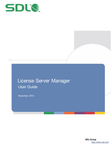
Chapter 1Product OverviewGuard Locking on Power to Release VersionsWith a Power to Release switch, the locking bolt extends when the guard isclosed with the actuator inserted in the switch and a lock command is issued tothe switch:Table 2 - Lock CommandModeOSSDGuardLink DescriptionThe lock signal (pin 5) is connected to 0V DCA lock command is issued to the switch on the CLU signal from a GuardLink safety master.IMPORTANTIf power is removed from a Power to Release switch in the locked position, thelocking bolt remains in its extended position (switch locked). Use the auxiliaryrelease to unlock the switch.ATTENTION: Under normal operating conditions, the locking bolt does not extend inthe absence of the actuator. The only exception is when power is removed from aswitch in the first 4 seconds of the start-up sequence. In this case, the bolt doesextend. If the guard door is closed when the start-up sequence is interrupted, theguard door is locked. Use the auxiliary release to unlock the switch.Guard Locking on Power to Lock VersionsWith a Power to Lock switch, the locking bolt extends when the guard is closedwith the actuator inserted in the switch and a lock command is issued to theswitch:Table 3 - Lock CommandModeOSSDGuardLinkDescriptionThe lock signal (pin 5) is connected to 24V DCA lock command is issued to the switch on the CLU signal from a GuardLink safety master.IMPORTANTIf power is removed from a Power to Lock switch or a fault occurs while in thelocked position, the bolt retracts and the switch unlocks.ATTENTION: Under normal operating conditions, the locking bolt does not extend inthe absence of the actuator. The only exception is when power is removed from aswitch in the first 4 seconds of the start-up sequence. In this case, the bolt doesextend. If the guard door is closed when the start-up sequence is interrupted, theguard door is locked. Use the auxiliary release to unlock the switch.Assembly OverviewActuatorLINK and DEVICEstatus indicators8Rockwell Automation Publication 440G-UM004C-EN-P - August 2020
Chapter 1Product SelectionProduct OverviewTable 4 - Catalog Number Explanation440G-MZSaOutputs (Safety/Auxiliary)CodeDescription20 Two safety/no aux20aSbNcRdJebcdeActuator CodeAuxiliary TypeLock TypeConnection TypeCode DescriptionS Standard codeUUnique codeCode DescriptionNNo auxiliaryCodeDescriptionR Power to ReleaseLPower to LockCode DescriptionJM12 5-pinTable 5 - Complete Switches, including Switch Body and ActuatorTypePower to ReleasePower to LockActuator CodingStandard (Low level to ISO 14119)Unique (High level to ISO 14119)Standard (Low level to ISO 14119)Unique (High level to ISO 14119)Escape ReleaseNoCat MZS20UNLJTable 6 - Spare ActuatorsDescriptionStandard code actuator (Low level to ISO 14119)Unique code actuator (High level to ISO 14119)Cat. No.440G-MZAS440G-MZAUTable 7 - AccessoriesDescriptionCat. No.L-shaped440G-MZAM1Z-shaped440G-MZAM2Actuator mounting bracketSwitch mounting bracket440G-MZAM3Padlock accessory440G-MZALRockwell Automation Publication 440G-UM004C-EN-P - August 20209
Chapter 1Product OverviewPackage ContentsThe box includes the following components:DescriptionPhotoSwitch BodyActuatorInstallation Instructions:publication 440G-IN01810Rockwell Automation Publication 440G-UM004C-EN-P - August 2020
Chapter2Safety ConceptSafety StandardsThe Guardmaster 440G-MZ safety switch satisfies applicable requirements inthe following standards that are related to functional safety and machineryassembly: Safety CertificationIEC 60947-5-3IEC 61508IEC 62061EN ISO 13849-1ISO 14119UL 508The 440G-MZ safety switch is certified for use in safety applications up to andincluding SIL 3 according to IEC 61508 and IEC 62061 with a proof test intervalof 20 years, and Performance Level e (PLe) Category 4 in compliance with ISO13849-1.Safety requirements are based on the standards applicable at the time ofcertification.The TÜV Rheinland group has approved the 440G-MZ safety switch for use insafety-related applications where PLe is required for the door positionmonitoring and guard locking functions.The 440G-MZ safety switch must be installed in accordance with the applicableregulation and standards.While the 440G-MZ safety switch can be used for SIL 3, PLe, and Category 4applications, the installation must comply with guard requirements (forexample, ISO 13854 and ISO 13857), and in some cases minimum (safe)distance requirements (for example, ISO 13855).The installed system, including the safety control system and the means bywhich the machine stops, must achieve the needed safety performance. The440G-MZ safety switch is one element in the safety system.Additional guidance on guards, guard locking and guard interlock can befound in: EN ISO 12100EN ISO 13854EN ISO 13855EN ISO 13857 EN ISO 14119EN ISO TR 24119EN ISO 14120Application-specific C-level standardsRockwell Automation Publication 440G-UM004C-EN-P - August 202011
Chapter 2Safety ConceptNotes:12Rockwell Automation Publication 440G-UM004C-EN-P - August 2020
Chapter3InstallationGeneral ConsiderationsInstallation must be in accordance with the present manual and implementedby qualified personnel exclusively. The 440G-MZ safety switch is intended to bepart of the safety-related control system of a machine.ATTENTION: Before installation, a thorough risk assessment must be performed todetermine whether the specifications of this device are suitable for all foreseeableoperational and environmental characteristics of the application.A functional test of the system is necessary to validate that it works as expected(see Functional Testing on page 17).Guard locking switches that use the Power to Lock principle (Cat. No.440G-MZS20*NLJ*) must only be used after a risk assessment has shown that theuse of a Power to Release principle (Cat. No. 440G-MZS20*NRJ*) is inappropriate.This assessment is necessary since the guard can be immediately opened after aloss of power supply or upon deactivation of the unlocking signal.Correct UseReview the following requirements and guidelines for proper use of the safetyswitch to achieve optimal performance. The 440G-MZ safety switch is designed for use on medium- and fullsized guards including guards where whole-body access to thesafeguarded area is possible.The switch is not to be used as a mechanical stop. Check that a separatedoor stop is used.A separately mounted latch (for example, magnetic or mechanical) isrecommended to maintain proper alignment of the actuator. Thelocking bolt must be free to enter and withdraw from the actuatorwithout binding.Use appropriate screws, bolts, or nuts that are fitted by tools to mountthe switch and actuator to avoid tampering.Do not over torque the mounting hardware.A minimum distance of 100 mm (3.94 in.) must separate adjacentswitches, see Pair Proximity on page 14.The 440G-MZ safety switch is designed for use in a NEC Class 2 circuit.Connect the 440G-MZ safety switch to a dedicated Class 2 power supplyor use electronic circuit protection (for example, 1692-ZRCLSS) toachieve NEC Class 2 compliance.ATTENTION: For the switch, actuator, and actuator mounting bracket: Only use the designated mounting holes. Never drill or use to support other structures such as a conduit, cable ways, or otherhardware.Rockwell Automation Publication 440G-UM004C-EN-P - August 202013
Chapter 3InstallationSwitch OrientationCan be used in all mounting orientations.Actuator OrientationThe actuator can approach the switch from three directions (Figure 1).Figure 1 - Three Directions of Approach231The flexible actuator can move in multiple axes to accommodate guard doormisalignment (Figure 2). For optimal performance, verify that the locking boltcan enter and withdraw from the tongue actuator without binding. Aseparately mounted door latch is recommended to avoid door misalignment.Figure 2 - Actuator FunctionPair ProximityIf a pair of 440G-MZ safety switches are mounted too close to one another, thetwo electromagnetic fields interact causing crosstalk, which can result innuisance faults and false operation.A minimum of 100 mm (3.94 in.) must separate a pair of switches to helpachieve correct operation (Figure 3 on page 14).Figure 3 - Minimum Distance between Switches [mm (in.)]100 (3.94)IMPORTANT14If the minimum separation distance is not observed, the electromagnetic fieldsinteract causing crosstalk. Crosstalk can result in nuisance faults and falseoperation.Rockwell Automation Publication 440G-UM004C-EN-P - August 2020
Chapter 3EnvironmentalConsiderationsInstallationThe 440G-MZ safety switch is rated for IP69K in accordance with ISO 20653and IP69 per IEC 60529. This rating involves a short-term test that is madewith high-pressure water jets at 80 C (176 F). The test is passed if no waterenters the enclosure of the switch that contains the electrical components andthe switch function is not impaired.This rating does not promise protection from any liquids other than water anddoes not promise the mechanical longevity from continuous or frequentexposure.Mount the Switch andActuatorATTENTION: Do not defeat, tamper, remove, or bypass this unit. Severe injury topersonnel could result.The presence of spare actuators can compromise the integrity of the safetysystems. Personal injury or death, property damage, or economic loss can result.Appropriate management controls, working procedures, and alternative protectivemeasures should be introduced to control their use and availability.Three M5 fasteners (not provided) are required for proper mounting of theswitch to a rigid guard door frame (Figure 4). Two M5 fasteners (not provided)are required to mount the actuator.Figure 4 - Required Mounting Hardware for Switch and Actuator2 x M53 x M5IMPORTANTDo not use a washer with the screw at the base of the switch body. Using awasher causes the plastic to crack.Loctite 242 thread-locking adhesive is known to cause stress cracks in theplastic housing of the 440G-MZ safety switch and should not be used. Lab testshave determined that Loctite 425, a cyanoacrylate adhesive, does not causecracking and can be considered if the faster cure time is acceptable in theapplication.Check the manufacturer specifications of any thread-locking compound usedto secure the screws. It is recommended to use a cyanoacrylate-typecompound. Other compounds can cause stress cracks in the plastic feet of theswitch.Rockwell Automation Publication 440G-UM004C-EN-P - August 202015
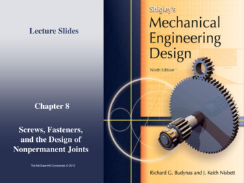
Chapter 3InstallationTypical ApplicationsThe 440G-MZ safety switch can be mounted on the inside or outside of ahinged or sliding guard door. The following shows three examples of theswitch and actuator mounted to a hinged or sliding guard door. Mount the switch on the inside of a hinged doorActuatorSwitchmountingbracket SwitchmountingbracketMount the switch on outside of a hinged doorActuatorZ-shaped ActuatorMounting BracketZ-shaped ActuatorMounting Bracket Mount the switch on a sliding doorActuator16L-shaped ActuatorMounting BracketRockwell Automation Publication 440G-UM004C-EN-P - August 2020L-shaped ActuatorMounting Bracket
Chapter 3Auxiliary ReleaseInstallationOperation of the auxiliary release causes a fault condition.To reset the switch, cycle the power or issue a RESET command over the link ina GuardLink safety system.Figure 5 - Auxiliary Release Operation [mm (in.)]5 (0.2)Top ViewPadlock AccessoryThe padlock accessory (Figure 6) can be inserted through the actuator openingof the 440G-MZ safety switch to help prevent the locking of the guard door andrestarting of the machine while an operator is inside the safeguarded area. Thepadlock accessory can accommodate up to three nominal 6.35 mm (0.25 in.)locks.Figure 6 - Padlock Accessory (Cat. No. 440G-MZAL)Up t
440G-MZ safety switches are classified as Type 4 interlocking devices with guard locking and the unique coded actuators are classified as having a high level of coding according to ISO 14119. The 440G-MZ safety switch features two OSSD outputs or a single-wire safety output when connected in a GuardLink system. These safety outputs are