Transcription
SI-GL42 Series Locking-Style SafetyInterlock SwitchInstruction ManualOriginal Instructions220476 Rev. B6 April 2022 Banner Engineering Corp. All rights reserved220476
SI-GL42 Series Locking-Style Safety Interlock SwitchContents1 Product Overview. 31.1 Models.31.2 Important. Read this before proceeding!.51.3 Overview. 52 Installation Instructions. 62.1 Installation Requirements.62.2 Pass-through hazards and Perimeter Guarding.72.3 Mechanical Installation.72.3.1 Position the Actuator Head.82.3.2 Install the Switch and Actuator. 82.3.3 Align the SI-QM-SMFA-2.102.3.4 Escape/Emergency/Auxiliary Release Mechanism. 102.4 Access the Wiring Chamber.132.4.1 Wiring the Terminals.132.5 Connection to a Machine. 133 Operating Instructions. 163.1 Checkout Procedures.163.1.1 Initial and Daily Checks. 163.1.2 Periodic Checks.164 Specifications4.1 Dimensions5 Accessories. 17. 18.215.1 Actuators and Unlock Mechanisms.215.2 Plastic Conduit Adapter.215.3 Cable Glands. 215.4 Universal (Input) Safety Modules.215.5 Safety Controllers.226 Product Support and Maintenance. 236.1 Repairs.236.2 EU/UK Declaration of Conformity (DoC). 236.3 Banner Engineering Corp. Limited Warranty. 23
SI-GL42 Series Locking-Style Safety Interlock Switch1 Product OverviewSI-GL42 Series Locking-Style Safety Interlock Switch for interlocking and position monitoring Positive opening safety contacts (per IEC 60947-5-1) Contact monitors both the presence of the actuator and if it is locked into the interlockChoice of two locking mechanism types: Spring lock with energized solenoid release Energized solenoid lock with spring releaseAll models have an integrated manual release mechanism (front and back)Four stainless steel actuator optionsActuator head rotatable in 90 increments providing five actuator positions (one verticaloption)Many different actuator and monitoring contact configurations to satisfy any applicationLightweight yet robust design (plastic body but the mechanically stressed components likethe rotating head are metal)IP67 environmental rating making the unit suitable for demanding industrial environments Insulated device (IEC 60947-5-1)M12 connector options (contact Banner Engineering for pre-wired M12 connector options) 1.1 ModelsA complete safety system is typically made up of two interlocks, two actuators, two cables, and a safety monitoring device.The use of an emergency release mechanism depends on the application.To order an interlock body model, insert S for Spring Lock/Solenoid Unlock or M for Solenoid Lock/Spring Unlock. Forexample: SI-GL42D 20-20 can become SI-GL42DM20-20 or SI-GL42DS20-20,Interlock nitorContactsActuator Engaged andLockedActuator Engaged but NotLockedActuator ContactsSI-GL42D 11-1124 VAC/DC1 NC/1 NO1 NC/1 NOActuator Contacts2221222122131413141314Solenoid Monitor Contacts323144E1 E2–Solenoid Monitor Contacts32312 NC1 NC/1 NO4443E1 Actuator ContactsSI-GL42D 20-11Actuator Contacts214324 VAC/DCActuator Unlocked andRemovedE2–Solenoid Monitor Contacts32314443E1 Actuator ContactsE2–Actuator Contacts111211121112212221222122Solenoid Monitor Contacts323143E1 44E2–Solenoid Monitor Contacts323143E1 www.bannerengineering.com - Tel: 1 888 373 676744E2–Solenoid Monitor Contacts323143E1 44E2–3
SI-GL42 Series Locking-Style Safety Interlock SwitchInterlock nitorContactsActuator Engaged andLockedActuator Engaged but NotLockedActuator ContactsSI-GL42D 21-1024 VAC/DC2 NC/1 NO1 NCActuator Contacts3231323132212221222122131413141314E1 E2–Solenoid Monitor Contacts4241E1 Actuator Contacts24 VAC/DC3 NC1 NCActuator Contacts2 NC1112212221222122313231323132E2–Solenoid Monitor Contacts4241E1 Actuator Contacts1112212221222122Solenoid Monitor Contacts323142E2–Solenoid Monitor Contacts32311431E1 314443E2–14E1 E1 14Solenoid Monitor Contacts222132314443E2–11E2–133244E1 Actuator Contacts124241Actuator ContactsSolenoid Monitor Contacts222132Solenoid Monitor Contacts22211 NCE2–13Actuator Contacts114241Solenoid Monitor Contacts3231Actuator ContactsSolenoid Monitor Contacts2221E1 24 VAC/DCActuator Contacts1243SI-GL42D 10-21E2–11132 NC/1 NOE1 12Actuator Contacts1 NOE2–Solenoid Monitor Contacts424111E1 24 VAC/DCActuator Contacts1241SI-GL42D 01-21E2–11Actuator Contacts2 NCE1 12E1 SI-GL42D 20-20E2–Solenoid Monitor Contacts424111Solenoid Monitor Contacts424124 VAC/DCActuator Contacts31Solenoid Monitor Contacts4241SI-GL42D 30-10Actuator Unlocked andRemovedE2–Actuator Contacts12Solenoid Monitor Contacts22211112Solenoid Monitor Contacts22212 NC/1 NO3143E1 32314443E2–E1 32314443E2–E1 3244E2–—Signifies which contacts are positive opening safety contacts (per IEC 60947-5-1). This contact is forced open by theaction of removing the actuator from the Interlock.—Signifies which contact is positively connected to the locking mechanism. This contact cannot close if the actuator is notpresent in the interlock.The model table lists only the interlock body, a required actuator is ordered separately. Emergency release mechanisms arealso ordered separately. For the complete lists of actuators and emergency release mechanisms see Accessories on page21.4www.bannerengineering.com - Tel: 1 888 373 6767
SI-GL42 Series Locking-Style Safety Interlock Switch1.2 Important. Read this before proceeding!The user is responsible for satisfying all local, state, and national laws, rules, codes, and regulations relating to the useof this product and its application. Banner Engineering Corp. has made every effort to provide complete application,installation, operation, and maintenance instructions. Please contact a Banner Applications Engineer with any questionsregarding this product.The user is responsible for making sure that all machine operators, maintenance personnel, electricians, and supervisorsare thoroughly familiar with and understand all instructions regarding the installation, maintenance, and use of this product,and with the machinery it controls. The user and any personnel involved with the installation and use of this product must bethoroughly familiar with all applicable standards, some of which are listed within the specifications. Banner Engineering Corp.makes no claim regarding a specific recommendation of any organization, the accuracy or effectiveness of any informationprovided, or the appropriateness of the provided information for a specific application.1.3 OverviewThe SI-GL42 Series Locking-Style Safety Interlock Switch with guard locking capability can be used to monitor the position ofa guard to detect its movement, opening, or removal.The SI-GL42 Interlock Switch can also be used to secure the guard in place to allow the hazard time to stop before the guardis opened. This allows the guard to be located closer to the hazard than otherwise possible in applications where the guardcan be opened and the hazard can be accessed. A guard can be a gate, door, cover, panel, barrier, or other physical meansthat separates individuals from the hazard. Safety switches will issue a signal to the machine control system to prevent orstop hazardous situations when the guard is not in the proper position.The SI-GL42 Interlock Switch is designed for guard locking applications. There are two styles available: Spring Lock, Solenoid Unlock (Models SI-GL42DS.)—The actuator is mechanically locked when it is fully insertedinto the actuator head. The actuator is unlocked by applying voltage to the solenoid. Solenoid Lock, Spring Unlock (Models SI-GL42DM.)—The fully inserted actuator is locked when voltage is applied tothe solenoid. The actuator is unlocked when voltage is removed from the solenoid.The SI-GL42 Interlock Switch is a type 2 locking fixture with an electromechanical latching device and low-level codingaccording to ISO 14119.Applications involving the use of the SI-GL42 Series Locking-Style Safety Interlock Switch should take into consideration thefollowing standards: EN ISO 13849-1 Safety-Related Parts of Control Systems EN ISO 12100 Safety of Machinery – General Principles for Design — Risk Assessment and Risk Reduction ISO 14119 (EN 1088) Interlocking Devices Associated with Guards – Principles for Design and Selection ISO 13857 Safety of Machinery – Safety Distances to Prevent Hazard Zones Being Reached ANSI B11.0 Safety of Machinery, General Requirements, and Risk Assessment ANSI B11.19 Performance Criteria for Safeguardingwww.bannerengineering.com - Tel: 1 888 373 67675
SI-GL42 Series Locking-Style Safety Interlock Switch2 Installation Instructions2.1 Installation RequirementsThe following general requirements and considerations apply to the installation of interlocked gates and guards for thepurpose of safeguarding. In addition, the user must refer to the relevant regulations and comply with all necessaryrequirements. See ANSI B11.19, or ISO 14119 and ISO 14120, or the appropriate standard.Hazards guarded by the interlocked guard must be prevented from operating until the guard is closed; a stop command mustbe issued to the guarded machine if the guard opens while the hazard is present. Closing the guard must not, by itself,initiate hazardous motion; a separate procedure must be required to initiate the motion. The safety switches must not beused as a mechanical or end-of-travel stop.Locate the guard an adequate distance from the danger zone (so the hazard has time to stop before the guard is openedsufficiently to provide access to the hazard). The guard must open either laterally or away from the hazard, not into thesafeguarded area. The guard also should not be able to close by itself and activate the interlocking circuitry. The installationmust prevent personnel from reaching over, under, around or through the guard to access the hazard. Any openings in theguard must not allow access to the hazard—see ANSI B11.19, ISO 13857, or the appropriate standard.The guard must be strong enough and designed to protect personnel and contain hazards within the guarded area that canbe ejected, dropped, or emitted by the machine. Design and install the safety switches and actuators so that they cannot beeasily defeated. Measures to minimize defeat (bypassing) of interlocking safety switches include: Minimizing motivation for defeating interlocking by providing training, supervision, and efficient means for machinesetup/adjustment, operation, and maintenance Limiting accessibility to the interlocking device, such as mounting out of reach, mounting behind a physicalobstruction, mounting in a concealed position Mounting them securely so that their physical position cannot shift, using reliable fasteners that require a tool toremove Preventing the switch or the actuator from being disassembled or repositioned that compromises the safety function(for example, welding, one-way screws, riveting)Mounting slots in the housing, if provided, are for initial adjustment only; final mounting holes (round) must be used forpermanent location. The switches, actuating systems, and actuators must not be used as a mechanical or end-of-travel stop.The normally closed safety contacts are of a "positive-opening" design. Positive-opening operation causes the contacts to beforced open, without the use of springs, when the actuator is disengaged or moved from its home position. In addition, theswitch(es) must be mounted in a "positive mode", to move/disengage the actuating system and actuator from its homeposition and open the normally closed contact, when the guard opens.The overall control concept, into which the switch has been integrated, must be validated in accordance with ISO 13849-2 orevaluated according to IEC 62061.See Mechanical Installation on page 7, Connection to a Machine on page 13, and Specifications on page 17.WARNING: Properly Install the Interlocked Guards Failure to follow these guidelines could result in serious injury or death. At a minimum, the interlocked guard must prevent hazards when not fully closed and must preventaccess to the hazards through any opening in the guard. Install the safety switches and actuators so they cannot be easily defeated and are not used as amechanical or end-of-travel stop. Mount at least one switch in a positive mode and verify it opensthe normally closed contact when the guard opens. The user must refer to the relevant regulations and comply with all necessary requirements. SeeANSI B11.19, or ISO 14119 and ISO 14120, or the appropriate standard.CAUTION: Do not use the safety switch as a mechanical or end-of-travel stop. Catastrophic damage can cause the safety switch to fail in an unsafe manner (that is, loss of theswitching action). Limit the movement or rotation of the guard to prevent damage to the safety switch or the actuator.6www.bannerengineering.com - Tel: 1 888 373 6767
SI-GL42 Series Locking-Style Safety Interlock SwitchWARNING: The hazard must be accessible only through the sensing field Incorrect system installation could result in serious injury or death. The installation of the SI-GL42 Interlock Switch must prevent any individual from reaching around,under, over or through the defined area and into the hazard without being detected. See OSHA CFR 1910.217, ANSI B11.19, and/or ISO 14119, ISO 14120 and ISO 13857 forinformation on determining safety distances and safe opening sizes for your guarding device.Mechanical barriers (for example, hard (fixed) guarding) or supplemental safeguarding might berequired to comply with these requirements.2.2 Pass-through hazards and Perimeter GuardingA pass-through hazard is associated with applications where personnel may pass through a safeguard (which issues a stopcommand to remove the hazard), and then continues into the guarded area, such as in perimeter guarding. Subsequently,their presence is no longer detected, and the related danger becomes the unexpected start or restart of the machine whilepersonnel are within the guarded area.Eliminate or reduce pass-through hazards whenever possible—see ANSI B11.19 and ANSI B11.20 or ISO 11161. Onemethod to mitigate the risk is to ensure that once tripped, either the safeguarding device, the safety related part of the controlsystem, or the guarded machine's MSCs/MPCEs will latch in an OFF condition. The latch must require a deliberate manualaction to reset that is separate from the normal means of machine cycle initiation.This method relies upon the location of the reset switch as well as safe work practices and procedures to prevent anunexpected start or restart of the guarded machine. All reset switches must be: Outside the guarded area Located to allow the switch operator a full, unobstructed view of the entire guarded area while the reset is performed Out of reach from within the guarded area Protected against unauthorized or inadvertent operation (such as through the use of rings or guards)If any areas within the guarded area are not visible from the reset switch, additional safeguarding must be provided.WARNING: Perimeter guarding applications Failure to observe this warning could result in serious injury or death. Use lockout/tagout procedures per ANSI Z244.1, or use additional safeguarding as described byANSI B11.19 safety requirements or other applicable standards if a passthrough hazard cannot beeliminated or reduced to an acceptable level of risk.2.3 Mechanical InstallationImportant: Install a safety switch in a manner which discourages tampering or defeat. Mount switches toprevent bypassing of the switching function at the terminal chamber or Quick Disconnect (QD). A switchand its actuator must never be used as a mechanical stop. Overtravel may cause damage to switch.All mounting hardware is supplied by the user. Fasteners must be of sufficient strength to guard against breakage. Use ofpermanent fasteners or locking hardware is recommended to prevent the loosening or displacement of the actuator and theswitch body. The mounting holes (5.3 mm) in the switch body accept M5 (#10) hardware. The mounting holes in the variousactuators accept M4 (#6) (for SI-QM-SSA-2, 4.5 mm) or M5 (#10) (for the other actuators, 5.1 or 5.5 mm).Mount the sensor and actuator such that the position cannot be changed after installation/adjustment. Mount the switchsecurely on a solid, stationary surface. Prevent the loosening of mounting hardware by using lock washers, thread-lockingcompound, etc. Only use slots for initial positioning. Pins, dowels, and splines can be used to prevent movement of theswitch and the actuator.Locate the switch body and actuator to allow access for functional checks, maintenance, service or replacement, andemergency/escape release (if needed). The installation should provide suitable clearances, be readily accessible, and allowaccess to the actuator and sensor.CAUTION: Do not overtighten the units during installation. Overtightening can twist the housing and affectthe sensor/switch performance.www.bannerengineering.com - Tel: 1 888 373 67677
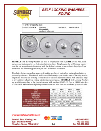
SI-GL42 Series Locking-Style Safety Interlock SwitchImportant: It is the responsibility of the machine builder (user) to make sure the wiring/cabling is not easilymanipulated by an operator to defeat the safety function(s); for example, cannot remove a switch from thesystem.Figure 1. Actuator minimum door radiusYXZEach actuator style has its own minimum door radius to ensure that its tongue smoothly enters the opening of the head of theswitch. SI-QM-SSA-2: 800 mm SI-QM-SSA-2RA: 600 mm SI-QM-SMFA-3: 400 mm SI-QM-SMFA-2: 150 mm2.3.1 Position the Actuator HeadThe actuator head can be rotated in increments of 90 to create eight possible actuator positions (four horizontal and fourvertical positions). Follow these steps to rotate the head.The actuator can enter the actuator head either horizontally (at a right angle to the switch length) or vertically (in-line with theswitch length). If vertical actuation is required, move the small cover from the opening in the top of the head to the opening inthe side of the head. To rotate the head:1.2.3.4.Loosen the four screws (TX10) on top of the actuator head.Set the actuator head to the desired direction.Tighten the four screws to 1.6 N·m.Verify the unused actuator slot is closed with the sealing cap.2.3.2 Install the Switch and ActuatorFollow these steps to mount the switch and actuator.CAUTION: When ambient temperatures are above 40 C, the housing temperature may be hot enough tocause a dangerous situation. Do not allow the housing to come into contact with people or with flammablematerial.1. Verify the mounting surface is flat.2. Mount the safety switch, tightening the four M5 (#10) screws to 2 N·m.3. Insert the actuator, in the correct position, into the head of the switch until the actuator molding rests against thehead's housing.8www.bannerengineering.com - Tel: 1 888 373 6767
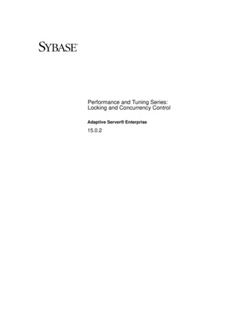
SI-GL42 Series Locking-Style Safety Interlock SwitchFigure 2. Actuator positionSI-GL42 HeadActuator fully insertedinto interlockActuator moulded part0.2 - 2There is a 2 mm overtravel between the switch head and the actuator. Set the guard's stop in this overtravel region(overtravel range 0.2–2 mm).4. Connect the actuator to the guard in a tamper-proof manner.Figure 3. Actuator dimensions and necessary minimal travelYpXScrew-on SurfaceNecessary Minimal TravelX29 3Y29 3pWhen the actuator is withdrawn from the switch's head, the active axis must be aligned in accordance to thetolerances shown.5. Verify no lateral forces are occurring between the actuator and the switch head.Refer to the dimensions drawing to see the fully inserted actuator placement.www.bannerengineering.com - Tel: 1 888 373 67679
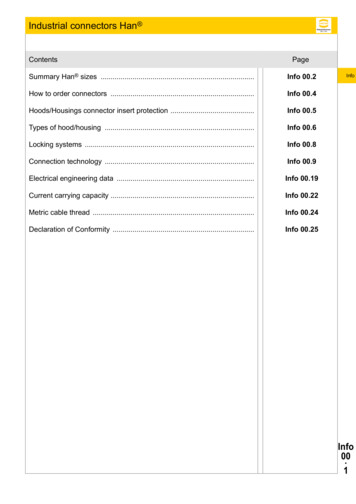
SI-GL42 Series Locking-Style Safety Interlock Switch2.3.3 Align the SI-QM-SMFA-2All measurements are listed in millimeters, unless noted otherwise.Figure 4. SI-QM-SMFA-2 dimensions121. Align and fasten SI-QM-SMFA-2 to the hinged guard as described in Install the Switch and Actuator on page 8.2. Loosen one of the small alignment screws (1) (whichever one is easiest to access with the door slightly open) untilthe actuator tongue (2) can be swiveled without spring force.3. Insert the actuator tongue (2) into the mounted switch head until the actuator comes into contact with the headhousing, the spring in the SI-QM-SMFA-2 must not be loaded.4. Pull the actuator tongue (2) out of the switch head by swinging the guard open 25 mm.The end of the tongue will still be in the opening of the switch head. The head must still be equipped with an antirotation device.5. Tighten the small alignment screw (1) to 1.5 N·m.6. Open and close the guard.The round shaft of the actuator tongue must only move in the spring bearing (actuator housing). The shaft must notsupport itself on the housing and cause an overload of the actuator tongue.7. Verify the actuator tongue moves into the switch head without colliding with the head. Verify the opposite smallalignment screw (1) was tightened with a torque of 1.5 N·m.2.3.4 Escape/Emergency/Auxiliary Release MechanismCAUTION: Before restarting normal operations, verify the auxiliary/escape/emergency release is in thelocked (protective) position.10www.bannerengineering.com - Tel: 1 888 373 6767
SI-GL42 Series Locking-Style Safety Interlock SwitchCAUTION: If the escape release mechanism is used, the switch must be mounted within the hazardousarea (must be accessible to an operator inside the hazardous area). The escape release mechanismshould only be used to exit the hazardous area in case of a system failure. The escape releasemechanism must not be accessible from outside of the hazardous area.Operating the Auxiliary Release MechanismThe auxiliary release mechanism is part of every switch. It is built into the cover.Figure 5. Auxiliary release mechanismAuxiliaryReleaseElementOperate the auxiliary release with only the 4 mm hexagon socket if the latching device fails.1. Raise the lock screw, TX10, enough so that the element can be turned.2. Turn the release element 90 with a hexagon wrench (M4, SW4). Fromto.The actuator can now be withdrawn. The NC contacts marked with this symbolwill open.3. Turn the release element back to its original position (locked) before restarting normal operation.4. Screw in the lock screw (0.5 N·m) and seal in place with the screw-locking compound.To prevent tampering, seal the rear access point (e.g. with locking compound) after installation if it is accessible.Install the Emergency Release MechanismAn emergency release mechanism can be installed on the front cover (SI-GL42-ERS-F-1) or on the back of the unit (SIGL42-ERS-B-1) depending on how the switch body is mounted.The emergency release mechanism can be used as an emergency release from outside the danger zone and as an escaperelease from inside the danger zone. It is the responsibility of the user to ensure the mounting complies with the requirementsof ISO 14119 or other appropriate standards.Figure 6. Emergency release mechanism1. Remove the lock screw.www.bannerengineering.com - Tel: 1 888 373 676711
SI-GL42 Series Locking-Style Safety Interlock Switch2. Place the mechanism onto the cover with the lock and unlock symbols toward the head of the switch and the sidenotches positioned over the cover mounting screws.3. Secure into place with the included mounting screws (torque to 0.5 N·m).4. Keep the key (flat piece of metal) in a secure location.The key is needed to reset from the unlocked to the locked position.Install the emergency release mechanism to the back of the switch body the same as for the cover, except: The lock screw does not need to be removed The lock, arrow, and unlock symbols should be oriented to match what is on the switch bodyUnlock the Emergency Release MechanismFollow these steps to unlock the actuator with the emergency release mechanism.1. Turn the lever element 90 in the clockwise direction.2. Remove the actuator.Reset the Emergency Release MechanismResetting the emergency release mechanism back to the locked position requires the key.Figure 7. Reset the emergency release mechanism24131. Turn the lever in the counterclockwise direction to the mounting screw position.2. While holding the lever in the counterclockwise direction, insert the key in the small slot near the lower mountingscrew. You should feel some resistance.3. Turn the lever as far as it will go in the counterclockwise direction. The lever should turn to the locked symbol.4. Remove the key.If the back-access point is unused and accessible when the switch is installed, seal the back-access point with a lockingcompound to prevent tampering.Installing the Escape Release MechanismAn Escape Release Mechanism can be mounted on the back of the unit and used as an escape release device for anoperator trapped inside the danger zone.It is the responsibility of the user to ensure the mounting complies with the requirements of ISO 14119 or other appropriatestandards. To attach the Escape Release Mechanism to the back of the switch:1. Align the arrow of the release mechanism with the arrow on the back of the switch body.2. Secure into place with the included mounting screws (torque to 0.5 N·m).To unlock the actuator with the Escape Release Mechanism, turn t
The SI-GL42 Interlock Switch is a type 2 locking fixture with an electromechanical latching device and low-level coding according to ISO 14119. Applications involving the use of the SI-GL42 Series Locking-Style Safety Interlock Switch should take into consideration the following standards: EN ISO 13849-1 Safety-Related Parts of Control Systems