Transcription
User ManualGuardmaster EtherNet/IP Network InterfaceCatalog Numbers 440R-ENETR
Important User InformationRead this document and the documents listed in the additional resources section about installation, configuration, andoperation of this equipment before you install, configure, operate, or maintain this product. Users are required tofamiliarize themselves with installation and wiring instructions in addition to requirements of all applicable codes, laws,and standards.Activities including installation, adjustments, putting into service, use, assembly, disassembly, and maintenance are requiredto be carried out by suitably trained personnel in accordance with applicable code of practice.If this equipment is used in a manner not specified by the manufacturer, the protection provided by the equipment may beimpaired.In no event will Rockwell Automation, Inc. be responsible or liable for indirect or consequential damages resulting from theuse or application of this equipment.The examples and diagrams in this manual are included solely for illustrative purposes. Because of the many variables andrequirements associated with any particular installation, Rockwell Automation, Inc. cannot assume responsibility orliability for actual use based on the examples and diagrams.No patent liability is assumed by Rockwell Automation, Inc. with respect to use of information, circuits, equipment, orsoftware described in this manual.Reproduction of the contents of this manual, in whole or in part, without written permission of Rockwell Automation,Inc., is prohibited.Throughout this manual, when necessary, we use notes to make you aware of safety considerations.WARNING: Identifies information about practices or circumstances that can cause an explosion in a hazardous environment,which may lead to personal injury or death, property damage, or economic loss.ATTENTION: Identifies information about practices or circumstances that can lead to personal injury or death, propertydamage, or economic loss. Attentions help you identify a hazard, avoid a hazard, and recognize the consequence.IMPORTANTIdentifies information that is critical for successful application and understanding of the product.Labels may also be on or inside the equipment to provide specific precautions.SHOCK HAZARD: Labels may be on or inside the equipment, for example, a drive or motor, to alert people that dangerousvoltage may be present.BURN HAZARD: Labels may be on or inside the equipment, for example, a drive or motor, to alert people that surfaces mayreach dangerous temperatures.ARC FLASH HAZARD: Labels may be on or inside the equipment, for example, a motor control center, to alert people topotential Arc Flash. Arc Flash will cause severe injury or death. Wear proper Personal Protective Equipment (PPE). Follow ALLRegulatory requirements for safe work practices and for Personal Protective Equipment (PPE).Allen-Bradley, ControlLogix, CompactLogix, Guardmaster, SoftLogix, Rockwell Software, Rockwell Automation, RSLogix, RSLinx, and TechConnect are trademarks of Rockwell Automation, Inc.Trademarks not belonging to Rockwell Automation are property of their respective companies.
PrefaceRead this preface to familiarize yourself with the rest of the manual. It providesinformation concerning: who should use this manual the purpose of this manual related documentation conventions used in this manualWho Should Use this ManualUse this manual if you are responsible for designing, installing, programming, ortroubleshooting control systems that use the 440R-ENETR Guardmaster EtherNet/IP network interface.Purpose of this ManualThis manual is a reference guide for the 440R-ENETR GuardmasterEtherNet/IP network interface, communications interface for GuardmasterSafety Relays. It describes the procedures you use to install, wire, configure,troubleshoot, and use these modules.ATTENTION: You must use firmware version 2 or later GuardmasterSafety Relays equipped with the optical bus with the interface.Firmware version 1 Guardmaster Safety Relays do not work with theinterface.Additional ResourcesThese documents contain additional information concerning related productsfrom Rockwell Automation.For Information AboutSee This PublicationPublication NumberNext Generation Safety Relays (GSR)Next Generation Safety Relays Overview BrochureEUSAFE-BR009AUsing EtherNet/IP for industrial controlEtherNet/IP Design Considerations Reference ManualENET-RM002ControlLogix Ethernet communication interface modulesControlLogix EtherNet/IP Bridge Module Installation Instructions1756-IN019EtherNet/IP Modules in Logix5000 Control Systems User ManualENET-UM001ControlLogix chassis and power supplies installationControlLogix Chassis and Power Supplies Installation Instructions1756-IN005ControlLogix systemsControlLogix System User Manual1756-UM001RSLinxRSLinx Classic Getting Results GuideLINX-GR001440R-ENETR interface installationGuardmaster Ethernet/IP Network Interface Installation Instructions 440R-IN078Installing an EtherNet/IP networkEtherNet/IP Media Planning and Installation ManualODVAYou can view or download publications athttp:/www.rockwellautomation.com/literature/. To order paper copies oftechnical documentation, contact your local Allen-Bradley distributor orRockwell Automation sales representative.Rockwell Automation Publication 440R-UM009B-EN-P - February 20143
PrefaceCommon Techniques Used inthis Manual4The following conventions are used throughout this manual: Bulleted lists such as this one provide information, not procedural steps. Numbered lists provide sequential steps or hierarchical information. Italic type is used for emphasis.Rockwell Software products contain extensive tutorials and help screens. Werecommend that you use these tutorials and help screens to learn about theproducts.For more information about Rockwell Software products, visit the RockwellSoftware website at ll Automation Publication 440R-UM009B-EN-P - February 2014
Table of ContentsPrefaceImportant User Information . . . . . . . . . . . . . . . . . . . . . . . . . . . . . . . . . . . . . . . . 2Who Should Use this Manual . . . . . . . . . . . . . . . . . . . . . . . . . . . . . . . . . . . . . . . 3Purpose of this Manual . . . . . . . . . . . . . . . . . . . . . . . . . . . . . . . . . . . . . . . . . . . . . 3Additional Resources . . . . . . . . . . . . . . . . . . . . . . . . . . . . . . . . . . . . . . . . . . . . . . . 3Common Techniques Used in this Manual. . . . . . . . . . . . . . . . . . . . . . . . . . . 4Chapter 1About the InterfaceOverview . . . . . . . . . . . . . . . . . . . . . . . . . . . . . . . . . . . . . . . . . . . . . . . . . . . . . . . . . . 7Important Interface Considerations . . . . . . . . . . . . . . . . . . . . . . . . . . . . . . . . . 7About the Interface . . . . . . . . . . . . . . . . . . . . . . . . . . . . . . . . . . . . . . . . . . . . . . . . 8Power Up a System . . . . . . . . . . . . . . . . . . . . . . . . . . . . . . . . . . . . . . . . . . . . . 8RIUP Situations. . . . . . . . . . . . . . . . . . . . . . . . . . . . . . . . . . . . . . . . . . . . . . . . 8Interface Features . . . . . . . . . . . . . . . . . . . . . . . . . . . . . . . . . . . . . . . . . . . . . . . . . . 8What the Interface Does. . . . . . . . . . . . . . . . . . . . . . . . . . . . . . . . . . . . . . . . . . . . 9Hardware/Software Compatibility . . . . . . . . . . . . . . . . . . . . . . . . . . . . . . . . . . 9Use of the Common Industrial Protocol (CIP) . . . . . . . . . . . . . . . . . . . . . 10Understand the Producer/Consumer Model . . . . . . . . . . . . . . . . . . . . . . . 10Specify the Requested Packet Interval (RPI) . . . . . . . . . . . . . . . . . . . . . . . . 11Support of Data Connections . . . . . . . . . . . . . . . . . . . . . . . . . . . . . . . . . . . . . 11Chapter Summary. . . . . . . . . . . . . . . . . . . . . . . . . . . . . . . . . . . . . . . . . . . . . . . . 11Chapter 2Install a Guardmaster EtherNet/IPNetwork InterfaceOverview . . . . . . . . . . . . . . . . . . . . . . . . . . . . . . . . . . . . . . . . . . . . . . . . . . . . . . . .Installation Summary. . . . . . . . . . . . . . . . . . . . . . . . . . . . . . . . . . . . . . . . . . . . .Mount the Interface on a DIN Rail . . . . . . . . . . . . . . . . . . . . . . . . . . . . . . . .Wiring Requirements and Recommendations. . . . . . . . . . . . . . . . . . .Grounding Considerations . . . . . . . . . . . . . . . . . . . . . . . . . . . . . . . . . . . .Chapter Summary. . . . . . . . . . . . . . . . . . . . . . . . . . . . . . . . . . . . . . . . . . . . . . . .131415161717Chapter 3Configure the Interface for YourEtherNet/IP NetworkOverview . . . . . . . . . . . . . . . . . . . . . . . . . . . . . . . . . . . . . . . . . . . . . . . . . . . . . . . .Configuration Requirements. . . . . . . . . . . . . . . . . . . . . . . . . . . . . . . . . . . . . .IP Address . . . . . . . . . . . . . . . . . . . . . . . . . . . . . . . . . . . . . . . . . . . . . . . . . . .Gateway Address . . . . . . . . . . . . . . . . . . . . . . . . . . . . . . . . . . . . . . . . . . . . .Subnet Mask . . . . . . . . . . . . . . . . . . . . . . . . . . . . . . . . . . . . . . . . . . . . . . . . .Set the Network Address . . . . . . . . . . . . . . . . . . . . . . . . . . . . . . . . . . . . . . . . .Set the Network Address for Guardmaster EtherNet/IP InterfaceUse the Rockwell BootP/DHCP Utility . . . . . . . . . . . . . . . . . . . . . . . . . . .Save the Relation List . . . . . . . . . . . . . . . . . . . . . . . . . . . . . . . . . . . . . . . . .Use DHCP Software to Configure Your Interface . . . . . . . . . . . . . . . . . .Chapter Summary. . . . . . . . . . . . . . . . . . . . . . . . . . . . . . . . . . . . . . . . . . . . . . . .Rockwell Automation Publication 440R-UM009A-EN-P - February 201419202021222323242627275
Table of ContentsChapter 4Automation ControllerCommunicationsOverview . . . . . . . . . . . . . . . . . . . . . . . . . . . . . . . . . . . . . . . . . . . . . . . . . . . . . . . .Ethernet Messaging. . . . . . . . . . . . . . . . . . . . . . . . . . . . . . . . . . . . . . . . . . . . . . .I/O Messaging . . . . . . . . . . . . . . . . . . . . . . . . . . . . . . . . . . . . . . . . . . . . . . . . . . .Logix Configuration . . . . . . . . . . . . . . . . . . . . . . . . . . . . . . . . . . . . . . . . . .EtherNet/IP Network Configuration with Add-on Profiles . . . . . .Accessing Module Data with Add-on Profiles . . . . . . . . . . . . . . . . . . .Explicit Messaging . . . . . . . . . . . . . . . . . . . . . . . . . . . . . . . . . . . . . . . . . . . .29292929303233Chapter 5Troubleshoot the InterfaceOverview . . . . . . . . . . . . . . . . . . . . . . . . . . . . . . . . . . . . . . . . . . . . . . . . . . . . . . . . 35Interpret the Status Indicators . . . . . . . . . . . . . . . . . . . . . . . . . . . . . . . . . . . . . 35Status Indicators for the Interface . . . . . . . . . . . . . . . . . . . . . . . . . . . . . . 35Appendix AEtherNet/IP Network InterfaceSpecificationsSpecifications . . . . . . . . . . . . . . . . . . . . . . . . . . . . . . . . . . . . . . . . . . . . . . . . . . . . 37Appendix BInterface Web DialogsWork with the Home Page . . . . . . . . . . . . . . . . . . . . . . . . . . . . . . . . . . . . . . . .Work with the Browse LSR Devices Page. . . . . . . . . . . . . . . . . . . . . . . . . . .Work with the Administrative Settings Pages . . . . . . . . . . . . . . . . . . . . . . .Use the Network Configuration Page . . . . . . . . . . . . . . . . . . . . . . . . . .Use the E-mail Configuration Page. . . . . . . . . . . . . . . . . . . . . . . . . . . . .3941424344Appendix CConfigure the RSLinx EthernetCommunication DriverOverview . . . . . . . . . . . . . . . . . . . . . . . . . . . . . . . . . . . . . . . . . . . . . . . . . . . . . . . .Install the RSLinx Software . . . . . . . . . . . . . . . . . . . . . . . . . . . . . . . . . . . . . . .Configure the AB ETH Driver . . . . . . . . . . . . . . . . . . . . . . . . . . . . . . . . . . .Configure the AB ETH/IP Driver . . . . . . . . . . . . . . . . . . . . . . . . . . . . . . . .45454648Appendix DTag Definitions6Tag Definitions . . . . . . . . . . . . . . . . . . . . . . . . . . . . . . . . . . . . . . . . . . . . . . . . . . 51Rockwell Automation Publication 440R-UM009A-EN-P - February 2014
Chapter1About the InterfaceOverviewThis chapter provides an overview of the Guardmaster EtherNet/IP NetworkInterface, its primary features, and how to use it.You need to understand the concepts discussed in this chapter to configure yourinterface and use it in an EtherNet/IP control system.This table lists where to find specific information.Important InterfaceConsiderationsTopicPageImportant Interface Considerations7About the Interface8Power Up a System8RIUP Situations8Interface Features8What the Interface Does9Hardware/Software Compatibility9Use of the Common Industrial Protocol (CIP)10Understand the Producer/Consumer Model10Specify the Requested Packet Interval (RPI)11Support of Data Connections11Before you begin using your interface, note the following importantconsiderations.ATTENTION: You must use firmware version 2 or later Guardmaster SafetyRelays equipped with the optical bus with the interface. Firmware version 1Guardmaster Safety Relays do not work with the interface.Rockwell Automation Publication 440R-UM009B-EN-P - February 20147
Chapter 1About the InterfaceAbout the InterfaceThe Guardmaster EtherNet/IP Network Interface provide connectivity toEtherNet/IP networks for Guardmaster Safety Relays.The interface is for the optical bus backplane that provides connectivity throughtwo RJ-45 connectors for 2-port pass-through support of daisy chain or ring, andthe existing star and tree network topologies.Power Up a SystemEach time the interface is powered up, the adapter compares the number of I/Omodules present on its backplane to the chassis size value from non-volatilememory. The adapter does not allow any I/O connection until the number ofI/O modules present equals the chassis size value minus one for the adapter itself.On power up, the interface assigns an address to every Guardmaster Safety Relay(up to six) in the backplane. The addressing starts from left to right with theGuardmaster Safety Relay to the immediate right of the interface taking the firstaddress of 1.RIUP SituationsYou must observe the following rules for Guardmaster Safety Relay systemconstruction and the removal and reinsertion of safety relays. Actual Guardmaster Safety Relay identification (such as, electronickeying) is done when connection establishment requests are received fromthe controller or controllers. The interface will not allow any I/Oconnections until the number and type of Guardmaster Safety Relaysmatch the configuration in the connection request. A Guardmaster Safety Relay removed under power disruptscommunication of the other Guardmaster Safety Relays in the system.Connections to all safety relays are disallowed until the entire system,including the interface, is power cycled to initiate re-addressing the system. If safety relays of different types are removed and returned to the wronglocations, attempts to connect to these safety relays will fail duringverification of the electronic ID (providing that keying has not beendisabled). If safety relays of the same type are removed and returned to the wronglocations, they accept connections from the controller or controllers oncethey pass their electronic keying check.Interface Features8Features of the interface include: Use of EtherNet/IP messages encapsulated within standard TCP/UDP/IP protocol Common application layer with ControlNet and DeviceNet networks Interfacing via Category 5 rated twisted pair cableRockwell Automation Publication 440R-UM009B-EN-P - February 2014
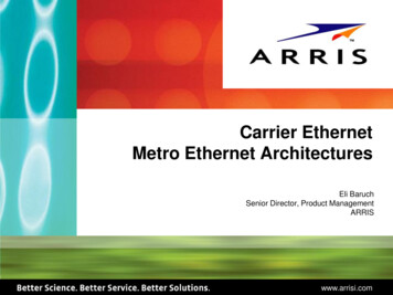
About the InterfaceChapter 1 Half/full duplex 10 Mbit or 100 Mbit operation DIN Rail mounting for 440R-ENETR interface Communication from Guardmaster Safety Relays on the same DIN Rail(mounted immediately to the right of the interface) as the 440R-ENETRinterface (when each safety relay is mounted to the right of the interfaceand each unit is within 5 mm of the next) to controllers on the EtherNet/IP network Communication supported by RSLinx software IP address assigned via standard BootP or DHCP tools Configuration via RSLogix 5000 software No network scheduling required No routing tables required Support of connections from multiple controllers simultaneouslyYou must use RSLogix 5000 to configure these features. For more details onconfiguration, see Configuration Requirements on in chapter 3.What the Interface DoesThe interface performs the following primary tasks: Real-time input data (also known as implicit messaging) - the interfaceserves as a bridge between Guardmaster Safety Relays and the networkL7XENBTEtherNet/IP NetworkE GuardmasterNSafetyETRelaysREN ControlLogixB I/OTOtherNetworkDevices Support of messaging data for programming information (also known asexplicit messaging)Hardware/SoftwareCompatibilityThe interface and the applications described in this manual are compatible withthe following firmware versions and software releases.Contact Rockwell Automation if you need software or firmware upgrades to usethis equipmentProductFirmware Revision/ Software Release440R-ENETR interface1.xx or later1756-ENBT2.3 or laterLogix controller19 or laterRSLogix 5000 software19 or laterRSLinx software2.52 or laterRockwell Automation Publication 440R-UM009B-EN-P - February 20149
Chapter 1About the InterfaceUse of the CommonIndustrial Protocol (CIP)ProductFirmware Revision/ Software ReleaseGSR DI (Catalog number 440R-D22R2)2 or laterGSR DIS (Catalog number 440R-D22S2)2 or laterGSR EM (Catalog number 440R-EM4R3)2 or laterGSR EMD (Catalog number 440R-EM4R2D)2 or laterGSR GLP (Catalog number 440R-GL2S1P)2 or laterGSR GLT (Catalog number 440R-GL2S2T)2 or laterThe adapter uses the Common Industrial Protocol (CIP). CIP is the applicationlayer protocol specified for EtherNet/IP, the Ethernet Industrial Protocol, as wellas for ControlNet and DeviceNet networks. It is a message-based protocol thatimplements a relative path to send a message from the producing device in asystem to the consuming devices.The producing device contains the path information that steers the messagealong the proper route to reach its consumers. Since the producing device holdsthis information, other devices along the path simply pass this information; theydo not store it.This has the following significant benefits: You do not need to configure routing tables in the bridging modules,which greatly simplifies maintenance and module replacement. You maintain full control over the route taken by each message, whichenables you to select alternative paths for the same end device.Understand the Producer/Consumer ModelThe CIP producer and consumer networking model replaces the old source anddestination (master and slave) model. The producer and consumer model reducesnetwork traffic and increases speed of transmission. In traditional I/O systems,controllers poll input modules to obtain their input status. In the CIP system,input modules are not polled by a controller. Instead, they produce (multicast orunicast) their data either upon a change of state (COS) or periodically.Multicast is the default mode for version 17 Logix and earlier controllers andunicast is the default for version 18 with multicast as a selectable option.The frequency of update depends upon the options chosen during configurationand where on the network the input module resides. The input module,therefore, is a producer of input data, and the controller is a consumer of the data.The controller also produces data for other controllers to consume. Theproduced and consumed data is accessible by multiple controllers and otherdevices over the EtherNet/IP network. This data exchange conforms to theproducer and consumer model.10Rockwell Automation Publication 440R-UM009B-EN-P - February 2014
About the InterfaceSpecify the Requested PacketInterval (RPI)Chapter 1The Requested Packet Interval or RPI is the update rate specified for a particularpiece of data on the network. The RPI can be specified for the interface andinclude all of the Guardmaster Safety Relays in the system.When you add an interface to the I/O configuration of a controller, you mustenter the RPI as a parameter. This value specifies how often to produce the datafor that device. For example, if you specify an RPI of 50 ms, it means that every50 ms the device should send its data to the controller and the controller shouldsend the consumed (output) data to the device.Use RPIs only for devices that exchange data. For example, a ControlLogixEtherNet/IP bridge module in the same chassis as the controller does not requirean RPI, because it is not a data-producing member of the system. Its use is only asa bridge to remote racks.Support of Data ConnectionsTheGuardmaster EtherNet/IP Network Interface supports data connections.A data connection to the interface is a grouping of data from one or moreGuardmaster Safety Relays into a single block of data sent over a singleconnection at the same data rate.See the EtherNet/IP Design Considerations Reference Manual,publicationENET-RM002 for more information on connections.Chapter SummaryIn this chapter, you were introduced to the features of the GuardmasterEtherNet/IP Network Interface, and considerations for installation and usage.Rockwell Automation Publication 440R-UM009B-EN-P - February 201411
Chapter 1About the InterfaceNotes:12Rockwell Automation Publication 440R-UM009B-EN-P - February 2014
Chapter2Install a Guardmaster EtherNet/IPNetwork InterfaceOverviewThis chapter describes how to physically install a Guardmaster EtherNet/IPnetwork interface; and how to mount the interface to DIN Rail.This table lists where to find specific information.TopicPageInstallation Summary14Mount the Interface on a DIN Rail15Install the Interface16Wiring Requirements and Recommendations16Grounding Considerations17ATTENTION: Environment and EnclosureThis equipment is intended for use in a Pollution Degree 2 industrialenvironment, in overvoltage Category II applications (as defined in IEC60664-1), at altitudes up to 2000 m (6562 ft) without derating.This equipment is not intended for use in residential environments and maynot provide adequate protection to radio communication services in suchenvironments.This equipment is supplied as open-type equipment. It must be mountedwithin an enclosure that is suitably designed for those specific environmentalconditions that will be present and appropriately designed to preventpersonal injury resulting from accessibility to live parts. The enclosure musthave suitable flame-retardant properties to prevent or minimize the spreadof flame, complying with a flame spread rating of 5VA or be approved for theapplication if nonmetallic. The interior of the enclosure must be accessibleonly by the use of a tool. Subsequent sections of this publication may containadditional information regarding specific enclosure type ratings that arerequired to comply with certain product safety certifications.In addition to this publication, see the following: Industrial Automation Wiring and Grounding Guidelines, publication 17704.1, for additional installation requirements NEMA 250 and IEC 60529, as applicable, for explanations of the degrees ofprotection provided by enclosuresRockwell Automation Publication 440R-UM009B-EN-P - February 201413
Chapter 2Install a Guardmaster EtherNet/IP Network InterfaceATTENTION: Prevent Electrostatic DischargeThis equipment is sensitive to electrostatic discharge, which can causeinternal damage and affect normal operation.Follow these guidelines when you handle this equipment: Touch a grounded object to discharge potential static Wear an approved grounding wrist strap Do not touch connectors or pins on component boards Do not touch circuit components inside the equipment Use a static-safe workstation, if available Store the equipment in appropriate static-safe packaging when not in useInstallation SummaryDo these steps to install a network interface.1. Mount the Interface on a DIN Rail.2. Install the Interface.SHOCK HAZARD: To prevent electrical shock, disconnect the EtherNet/IPnetwork interface from it power source before installing or servicing. Install insuitable enclosure. Keep free from contaminants.ATTENTION: An incorrectly applied or installed EtherNet/IP networkinterface can result in damage to the components or reduction in productlife. Wiring or application errors (e.g. supplying incorrect or inadequatesupply voltage or operating/storing in excessive ambient temperatures) mayresult in malfunction of the product.ATTENTION: Only personnel familiar with the EtherNet/IP network interfaceand associated machinery should plan to install, set up, and maintain thesystem. Failure to comply may result in personal injury and/or equipmentdamage.ATTENTION: This is a Class A product. In a domestic environment, thisproduct may cause radio interference in which case the user may be requiredto take adequate measures.14Rockwell Automation Publication 440R-UM009B-EN-P - February 2014
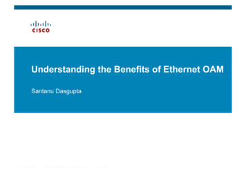
Install a Guardmaster EtherNet/IP Network InterfaceChapter 2Use the figure to identify the external features of your interface.Figure 1 - Physical Features of the 440R-ENETR Interface12345DescriptionMount the Interface on a DINRailDescription1Removable terminal block4Network address rotary switches2Status indicators5Ethernet network RJ-45 connectors3Optical communications linkFollow these steps to mount the interface on a DIN Rail.ATTENTION: To avoid overheating, the unit must be mounted vertically andrequires 37.4 mm (1.5 in.) of clearance at the top and the bottom to allowadequate ventilation. The temperature ratings for the unit will be derated ifnot mounted in this manner.1. Position the adapter vertically above an IEC standard (35x7.5x1 mm) tophat DIN Rail at a slight angle (DIN Rail: Cat. No. 199-DR1; 46277-3).2. Press down firmly to install the interface on the DIN Rail.3. Set the network address switches to the desired value. See Set the NetworkAddress in chapter 3 for more details on setting the IP address.To remove your interface from the DIN Rail, pry the DIN Rail latch downwardsuntil there is separation from the latch and the DIN Rail.Rockwell Automation Publication 440R-UM009B-EN-P - February 201415
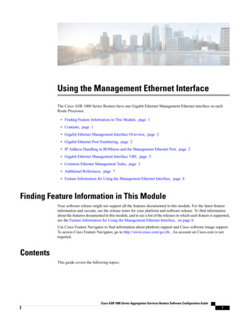
Chapter 2Install a Guardmaster EtherNet/IP Network InterfaceInstall the InterfaceInstall the interface to the left of Guardmaster Safety Relays equipped with anoptical communication bus. There must be no more than 5 mm horizontalseparation between two adjacent relays for the optical communication bus tooperate properly.Wiring Requirements and Recommendations Allow for at least 50 mm (2 in.) between I/O wiring ducts or terminalstrips and the interface. Separate wiring by signal type. Bundle wiring with similar electricalcharacteristics together. Label wiring to all devices in the system. Use tape, shrink-tubing, or otherdependable means for labeling purposes. In addition to labeling, usecolored insulation to identify wiring based on signal characteristics. Forexample, you may use blue for DC wiring and red for AC wiring.Refer to the following illustration to wire the interface.A1 SupplyEthernetRJ-45connectorA2 CommonTOP VIEWATTENTION: Do not connect 120/240V AC power to the A1/A2 DC supply.ATTENTION: Do not wire more than two conductors on any single terminal.Table 1 - Wire RequirementsWire SizeType440R- ENETR SolidMinMax0.14 mm2 (26 AWG)2.5 mm2 (14 AWG)Stranded16Rockwell Automation Publication 440R-UM009B-EN-P - February 20141.5 mm2 (16 AWG)Rated @ 90 ºC (194 ºF)insulation max
Install a Guardmaster EtherNet/IP Network InterfaceChapter 2Grounding ConsiderationsThe grounding and bonding must be of equal potential between all devices in thecommunication coverage area.ATTENTION: If this equipment is used in a manner not specified by themanufacturer, the protection provided by the equipment may be impaired.Chapter SummaryIn this chapter, you learned how to install and wire your Guardmaster EtherNet/IP network interface. The following chapter describes how to configure yourGuardmaster EtherNet/IP network interface to communicate on the EtherNet/IP network by providing an IP address, gateway address, and Subnet mask.Rockwell Automation Publication 440R-UM009B-EN-P - February 201417
Chapter 2Install a Guardmaster EtherNet/IP Network InterfaceNotes:18Rockwell Automation Publication 440R-UM009B-EN-P - February 2014
Chapter3Configure the Interface for Your EtherNet/IP NetworkOverviewBefore using your interface in an EtherNet/IP network, you need to configure itwith an IP address, subnet mask, and optional Gateway address. This chapterdescribes these configuration requirements and the procedures for providingthem. Here are ways you can do this: Use the Rockwell BootP/DHCP utility, version 2.3 or later, that shipswith RSLogix 5000 or RSLinx software.– You can also use this utility to reconfigure a device with an IP addressyou must change. Use a third party DHCP server. Use the Network Address rotary switches. Have your network administrator configure the interface via the networkDHCP server.See the table for a list of where to find information in this chapter.TopicPageConfiguration Requirements20IP Address20Gateway Address21Subnet Mask22Set the Network AddressSet the Network Address for Guardmaster EtherNet/IP InterfaceUse the Rockwell BootP/DHCP UtilitySave the Relation ListUse DHCP Software to Configure Your InterfaceRockwell Automation Publication 440R-UM009B-EN-P - February 2014232324262719
Chapter 3Configure the Interface for Your EtherNet/IP NetworkConfiguration RequirementsBefore you
On power up, the interface assigns an address to every Guardmaster Safety Relay (up to six) in the backplane. The addressing starts from left to right with the Guardmaster Safety Relay to the immediate right of the interface taking the first address of 1. RIUP Situations You must observe the following rules for Guardmaster Safety Relay system