Transcription
User ManualOriginal InstructionsTLSZ Guardmaster Guard Locking SwitchCatalog Numbers 440G-TZS21UPRH, 440G-TZS21UPLH, 440G-TZS21UTRH, 440G-TZS21UTLH
Important User InformationRead this document and the documents listed in the additional resources section about installation, configuration, andoperation of this equipment before you install, configure, operate, or maintain this product. Users are required tofamiliarize themselves with installation and wiring instructions in addition to requirements of all applicable codes, laws,and standards.Activities including installation, adjustments, putting into service, use, assembly, disassembly, and maintenance arerequired to be carried out by suitably trained personnel in accordance with applicable code of practice.If this equipment is used in a manner not specified by the manufacturer, the protection provided by the equipment maybe impaired.In no event will Rockwell Automation, Inc. be responsible or liable for indirect or consequential damages resulting fromthe use or application of this equipment.The examples and diagrams in this manual are included solely for illustrative purposes. Because of the many variables andrequirements associated with any particular installation, Rockwell Automation, Inc. cannot assume responsibility orliability for actual use based on the examples and diagrams.No patent liability is assumed by Rockwell Automation, Inc. with respect to use of information, circuits, equipment, orsoftware described in this manual.Reproduction of the contents of this manual, in whole or in part, without written permission of Rockwell Automation,Inc., is prohibitedThroughout this manual, when necessary, we use notes to make you aware of safety considerations.WARNING: Identifies information about practices or circumstances that can cause an explosion in a hazardousenvironment, which may lead to personal injury or death, property damage, or economic loss.ATTENTION: Identifies information about practices or circumstances that can lead to personal injury or death, propertydamage, or economic loss. Attentions help you identify a hazard, avoid a hazard, and recognize the consequence.IMPORTANTIdentifies information that is critical for successful application and understanding of the product.Labels may also be on or inside the equipment to provide specific precautions.SHOCK HAZARD: Labels may be on or inside the equipment, for example, a drive or motor, to alert people that dangerousvoltage may be present.BURN HAZARD: Labels may be on or inside the equipment, for example, a drive or motor, to alert people that surfaces mayreach dangerous temperatures.ARC FLASH HAZARD: Labels may be on or inside the equipment, for example, a motor control center, to alert people topotential Arc Flash. Arc Flash will cause severe injury or death. Wear proper Personal Protective Equipment (PPE). Follow ALLRegulatory requirements for safe work practices and for Personal Protective Equipment (PPE).
Table of ContentsPrefaceWho Should Use This Manual . . . . . . . . . . . . . . . . . . . . . . . . . . . . . . . . . . .5Purpose of This Manual . . . . . . . . . . . . . . . . . . . . . . . . . . . . . . . . . . . . . . . . .5Conventions Used in This Manual . . . . . . . . . . . . . . . . . . . . . . . . . . . . . . .5Additional Resources . . . . . . . . . . . . . . . . . . . . . . . . . . . . . . . . . . . . . . . . . . . .5Terminology . . . . . . . . . . . . . . . . . . . . . . . . . . . . . . . . . . . . . . . . . . . . . . . . . . .6General DescriptionGuardmaster TLSZ Overview . . . . . . . . . . . . . . . . . . . . . . . . . . . . . . . . . . .7Catalog Numbering . . . . . . . . . . . . . . . . . . . . . . . . . . . . . . . . . . . . . . . . . . . . .7Packaging Contents . . . . . . . . . . . . . . . . . . . . . . . . . . . . . . . . . . . . . . . . . . . . .8InstallationGeneral Considerations . . . . . . . . . . . . . . . . . . . . . . . . . . . . . . . . . . . . . . . . .9Actuator/Target Mounting . . . . . . . . . . . . . . . . . . . . . . . . . . . . . . . . . . . . . .9Allowable Approach Directions . . . . . . . . . . . . . . . . . . . . . . . . . . . . . . . . . .9Minimum Operating Radius . . . . . . . . . . . . . . . . . . . . . . . . . . . . . . . . . . . 10Manual Release . . . . . . . . . . . . . . . . . . . . . . . . . . . . . . . . . . . . . . . . . . . . . . . 10Manual Override Cover . . . . . . . . . . . . . . . . . . . . . . . . . . . . . . . . . . . . . . . 11Pair Proximity . . . . . . . . . . . . . . . . . . . . . . . . . . . . . . . . . . . . . . . . . . . . . . . . 12Guide Repositioning . . . . . . . . . . . . . . . . . . . . . . . . . . . . . . . . . . . . . . . . . . 12Steel Locking Bolts . . . . . . . . . . . . . . . . . . . . . . . . . . . . . . . . . . . . . . . . . . . . 12Actuator Clearance . . . . . . . . . . . . . . . . . . . . . . . . . . . . . . . . . . . . . . . . . . . 13Dimensions . . . . . . . . . . . . . . . . . . . . . . . . . . . . . . . . . . . . . . . . . . . . . . . . . . 14WiringConnections . . . . . . . . . . . . . . . . . . . . . . . . . . . . . . . . . . . . . . . . . . . . . . . . .OSSD Inputs . . . . . . . . . . . . . . . . . . . . . . . . . . . . . . . . . . . . . . . . . . . . . . . . .OSSD Outputs . . . . . . . . . . . . . . . . . . . . . . . . . . . . . . . . . . . . . . . . . . . . . . .Auxiliary Output . . . . . . . . . . . . . . . . . . . . . . . . . . . . . . . . . . . . . . . . . . . . .Lock Command . . . . . . . . . . . . . . . . . . . . . . . . . . . . . . . . . . . . . . . . . . . . . .1717171818CommissioningPreparation . . . . . . . . . . . . . . . . . . . . . . . . . . . . . . . . . . . . . . . . . . . . . . . . . .First Time Power-up . . . . . . . . . . . . . . . . . . . . . . . . . . . . . . . . . . . . . . . . . .Learning First Target . . . . . . . . . . . . . . . . . . . . . . . . . . . . . . . . . . . . . . . . . .Learning Additional Targets . . . . . . . . . . . . . . . . . . . . . . . . . . . . . . . . . . .Commissioning Errors . . . . . . . . . . . . . . . . . . . . . . . . . . . . . . . . . . . . . . . .Power-up Self Check . . . . . . . . . . . . . . . . . . . . . . . . . . . . . . . . . . . . . . . . . .192020202121Functional TestingFunctional Testing . . . . . . . . . . . . . . . . . . . . . . . . . . . . . . . . . . . . . . . . . . . . 23Rockwell Automation Publication 440G-UM001C-EN-P - January 20183
Table of ContentsApplication and Wiring Examples Wiring to GLP Relay . . . . . . . . . . . . . . . . . . . . . . . . . . . . . . . . . . . . . . . . . . 25Wiring to GLT Relay . . . . . . . . . . . . . . . . . . . . . . . . . . . . . . . . . . . . . . . . .Wiring to DI and EMD Relay . . . . . . . . . . . . . . . . . . . . . . . . . . . . . . . . .Wiring to DG Relay . . . . . . . . . . . . . . . . . . . . . . . . . . . . . . . . . . . . . . . . . .Wiring to CR30 Relay . . . . . . . . . . . . . . . . . . . . . . . . . . . . . . . . . . . . . . . .Wiring to 1734 Guard Point I/O . . . . . . . . . . . . . . . . . . . . . . . . . . . . . .Wiring to 1732 ArmorBlock . . . . . . . . . . . . . . . . . . . . . . . . . . . . . . . . . . .262830313237Diagnostics and Troubleshooting Tools Needed . . . . . . . . . . . . . . . . . . . . . . . . . . . . . . . . . . . . . . . . . . . . . . . . 43Required Tools . . . . . . . . . . . . . . . . . . . . . . . . . . . . . . . . . . . . . . . . . . . . . . .Optional Tools . . . . . . . . . . . . . . . . . . . . . . . . . . . . . . . . . . . . . . . . . . . . . . .Flowchart . . . . . . . . . . . . . . . . . . . . . . . . . . . . . . . . . . . . . . . . . . . . . . . . . . . .Step 1 — Status Indicator OFF . . . . . . . . . . . . . . . . . . . . . . . . . . . . . . . .Step 2 — Status Indicator Flashing Red at 4 Hz . . . . . . . . . . . . . . . . .Wrong Target . . . . . . . . . . . . . . . . . . . . . . . . . . . . . . . . . . . . . . . . . . . . . . . .Missing Target . . . . . . . . . . . . . . . . . . . . . . . . . . . . . . . . . . . . . . . . . . . . . . .Target Not Mounted Correctly . . . . . . . . . . . . . . . . . . . . . . . . . . . . . . . .Pair Proximity . . . . . . . . . . . . . . . . . . . . . . . . . . . . . . . . . . . . . . . . . . . . . . . .Mechanical Pressure on Safety Gate . . . . . . . . . . . . . . . . . . . . . . . . . . . .Long Wiring . . . . . . . . . . . . . . . . . . . . . . . . . . . . . . . . . . . . . . . . . . . . . . . . .Voltage Supply Dips . . . . . . . . . . . . . . . . . . . . . . . . . . . . . . . . . . . . . . . . . .Rapid Locking . . . . . . . . . . . . . . . . . . . . . . . . . . . . . . . . . . . . . . . . . . . . . . . .Step 3 - Status Indicator Flashes Red at 1 Hz . . . . . . . . . . . . . . . . . . . .Capacitive Loading . . . . . . . . . . . . . . . . . . . . . . . . . . . . . . . . . . . . . . . . . . .Step 4 — Status Indicator Flashes Green at 1 Hz . . . . . . . . . . . . . . . .Step 5 — Flashing Red and Green . . . . . . . . . . . . . . . . . . . . . . . . . . . . . .Step 6 — Indicator Solid Red . . . . . . . . . . . . . . . . . . . . . . . . . . . . . . . . . .Step 7 — Other Considerations . . . . . . . . . . . . . . . . . . . . . . . . . . . . . . . .Distribution Block . . . . . . . . . . . . . . . . . . . . . . . . . . . . . . . . . . . . . . . . . . . .GSR Relays on Power-up . . . . . . . . . . . . . . . . . . . . . . . . . . . . . . . . . . . . . cations and Safety Ratings Specifications . . . . . . . . . . . . . . . . . . . . . . . . . . . . . . . . . . . . . . . . . . . . . . . . . 55Safety Ratings . . . . . . . . . . . . . . . . . . . . . . . . . . . . . . . . . . . . . . . . . . . . . . . . 564Rockwell Automation Publication 440G-UM001C-EN-P - January 2018
PrefaceRead this preface to familiarize yourself with the rest of the manual. It providesinformation concerning: Who would use this manual The purpose of this manual Related documentation Conventions used in this manualWho Should Use This ManualUse this manual to design, install, program, or troubleshoot systems that usethe TLSZ Guardmaster guard locking safety switches.You are required to have a basic understanding of electrical circuitry andfamiliarity with safety-related control systems. If you do not, obtain the propertraining before using this product.Purpose of This ManualThis manual is a reference guide for the Guardmaster TLSZ guard lockingswitch. It describes the procedures you use to install, wire, and troubleshootyour switch. This manual: Explains how to install and wire your TLSZ switch, Provides an overview of the Guardmaster TLSZ guard locking switch.Conventions Used in ThisManualThe following conventions are used throughout this manual: Bulleted lists such as this one provide information, not procedural steps. Numbered lists provide sequential steps or hierarchical information.Additional ResourcesThe following documents offers additional information about relatedRockwell Automation products.ResourceDescriptionIndustrial Automation Wiring and Grounding Guidelines, Provides general guidelines for installation of aRockwell Automation industrial system.publication 1770-4.1Product Certifications website, rok.auto/certificationsProvides declarations of conformity, certificates for theTLSZ guard locking switch.Rockwell Automation Functional Safety Data SheetProvides functional safety data and details forRockwell Automation products.Guardmaster 440C-CR30 Configurable Safety RelayWiring DiagramsProvides example wiring diagrams for the CR30 softwareconfiguration safety relay.Allen-Bradley Industrial Automation GlossaryGlossary of industrial automation terms andabbreviationsYou can view and download publications at http://www.rockwellautomation.com/literature/ . To order paper copies of technicaldocuments, contact your local Rockwell Automation distributor or salesrepresentative.Rockwell Automation Publication 440G-UM002A-EN-P - March 20195
PrefaceTerminology6The Industrial Automation Glossary contains terms and abbreviations used byRockwell Automation to describe industrial automation systems. Below is a listof specific terms and abbreviations used in this manual.NCNo connectionN.C. (NormallyClosed)An electrical contact whose normal state (for example,no pressure or electrical potential applied) is in theclosed position.N.O. (NormallyOpen)An electrical contact whose normal state (i.e., nopressure or electrical potential applied) is in the openposition.PLCA programmable logic controller or a programmableautomation controller.PTL (Power toLock)Apply 24V to the lock command to lock the switch. Thiscommand applies to the TLSZL switch.PTL (Power toRelease)Apply 24V to the lock command to unlock the switch.This command applies to the TLSZR switch.Reaction TimeDescribes the time between the true state of the input tothe ON state of the output.Response TimeDescribes the time between the trigger of the input tothe OFF state of the output. Throughout this manual,the safety outputs may be described as turning offimmediately. This means that the safety outputs willturn off within the response time.RFIDRadio frequency identification.OSSD (OutputSignalSwitchingDevice)Typically a pair of solid-state signals pulled up to the DCsource supply. The signals are usually tested for shortcircuits to the DC power supply, short circuits to theDC common, and short circuits between the twosignals.StandardcodingSame as Low coding as defined in EN ISO 14119:2013TLSZLTLSZ power-to-lock guard locking switchTLSZRTLSZ power-to-release guard locking switchUnique codingSame as High coding as defined in EN ISO 14119:2013Rockwell Automation Publication 440G-UM002A-EN-P - March 2019
Chapter1General DescriptionGuardmaster TLSZ OverviewThis Guardmaster TLSZ guard locking switch functions by locking itactuator, which prohibits the opening of a guard.The TLSZ uses radio frequency identification, RFID, coding to detect theappropriate target.This version of the Guardmaster TLSZ guard locking switch features OSSDoutputs. These outputs are enabled only when the actuator is locked and the RFtarget is sensed.This device is intended to be part of the safety-related control system of amachine. Perform a risk assessment before installation to determine whetherthe specifications of this device are suitable for all operational andenvironmental characteristics of the machine. See Specifications on page 55 forcertification information and ratings.Use nonremovable screws, bolts, or nuts to mount the switch and actuators. Donot over torque the mounting hardware.TLSZ guard locking switches are classified according to ISO 14119 as Type 4switching devices. The RFID targets are classified as having a high level ofcoding.Measures are to be taken to minimize the need to defeat and to manage the useand availability of spare RFID targets.Rockwell Automation Publication 440G-UM002A-EN-P - March 20197
Chapter 1General DescriptionCatalog NumbersThe schema for the TLSZ catalog number is shown in Table 1. The parts of theschema are shown in Table 2.Table 1 - TLSZ Catalog Number Setup440GTZS21UPRH123456789Table 2 - TLSZ Catalog Number DetailParameterValueDescription1440Safeguards the Product2GGuard locking switch3TTitan Locking Switch4ZPLe rated, cascadable safety signals5S21Solid-state outputs, 2 safety (OSSD), 1 aux6UUnique coded RFID target7PTAux signal shows lock statusAux signal shows door status8RLPower to ReleasePower to Lock9H8-pin M12 QD connectorATTENTION: Guard lock switches that use the Power to Lock principle canonly be used after a risk assessment has shown that the Power to Releaseprinciple is inappropriate for the application. If a power supply loss occurswith Power to Lock switches, the switches immediately become unlockedand the user may have access to the hazards.8Rockwell Automation Publication 440G-UM002A-EN-P - March 2019
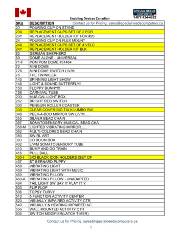
General DescriptionPackaging ContentsChapter 1Figure 1 shows the contents in the shipping package. The contents include: Switch Actuator RFID target T20 security Torx bit Two steel bolts and nuts Plug Installation instructions (not shown)Figure 1 - Package ContentsRockwell Automation Publication 440G-UM002A-EN-P - March 20199
Chapter 1General DescriptionNotes:10Rockwell Automation Publication 440G-UM002A-EN-P - March 2019
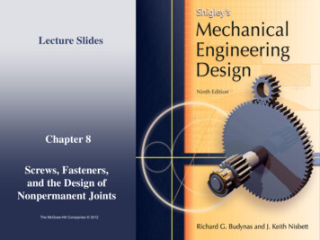
Chapter2InstallationGeneral ConsiderationsThe TLSZ guard locking switch is designed for use on guards that are engineered tobe rigid and without sag. The TLSZ uses radio frequency identification, RFID,coding to detect the appropriate target.Actuator/Target MountingFigure 2 shows the correct and incorrect ways to mount the target with theactuator.The TLSZ must only be used with the fully flexible actuator. The replacementpart number for the actuator is catalog number 440G-A27143.Figure 2 - Target/Actuator MountingTargetActuator Rockwell Automation Publication 440G-UM002A-EN-P - March 2019 11
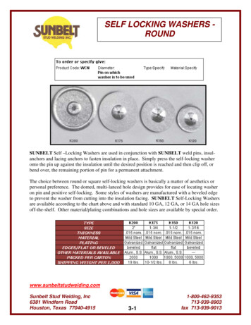
Chapter 2InstallationAllowable ApproachDirectionsThe actuator and target must be always mounted as “close coupled” and canapproach the switch in any of the three entry slot positions that are shown inFigure 3. Approach from the underside is not allowed, as the distance from thetarget to the internal RF sensor is too far for reliable operation.Figure 3 - Allowable Approach DirectionThis approach requiresguide repositioning, seepage 14.Minimum Operating RadiusWhen applied to hinged doors, the minimum operating distances along thelength and perpendicular is shown in Figure 4.Figure 4 - Minimum Operating Distance [mm (in.)]80 (3.19)80 (3.19)80 (3.19)80 (3.19)Figure 5 shows the location of the two 1.5 mm (0.06 in.) set screws that can beadjusted to preset the actuator to an optimal angle, if needed.Figure 5 - Actuator Set Screw1.5 mm (0.06 in.)12Rockwell Automation Publication 440G-UM002A-EN-P - March 2019
InstallationManual ReleaseChapter 2The manual release feature only applies to TLSZR (Power to Release) switch.In some cases, you must manually release the locked actuator.Figure 6 shows the two locations from which the actuator can be manuallyreleased.1. Remove the T20 Torx screw.2. To release the actuator, insert a small screwdriver or rod in the hole.If power is applied to the switch when the actuator is released, the OSSD safetyoutputs turn OFF and the switch goes to a faulted state with the statusindicator flashing red at 4 Hz. Power then has to be cycled to the switch toreturn it to an operational state.Figure 6 - Manual Release31T2022 2.5 (0.10) ØManual Override CoverFigure 7 on page 14 shows an optional cover that is available only for theTLSZR (Power to Release) switch. This cover has a lever that allows you tomanually unlock the actuator at any time. Rotate the lever 90 to unlock theactuator.If power is applied to the switch when the actuator is released, the OSSD safetyoutputs turn OFF, and the switch goes to a faulted state with the statusindicator flashing red at 4 Hz. Power is then cycled to the switch to return it toan operational state.Rockwell Automation Publication 440G-UM002A-EN-P - March 201913
Chapter 2InstallationFigure 7 - Manual Override Cover121.2 N m (10.62 lb in)90 90 Pair ProximityIf a pair of TLSZ switches are mounted too close to each other, the two RFfields could interact causing crosstalk. Cross talk results in nuisance faults.An absolute minimum of 200 mm (8 in.) must be used to help achieve correctoperation.The restriction also applies if a TLSZ switch is mounted close to the 440G-LZguard locking and the 440N-Z SensaGuard switches.Guide RepositioningThe actuator guide can be repositioned to facilitate alignment of the actuator.In steps 8 11, rotate the metal guide to allow the switch body to be fastenedflush to the mounting surface.Figure 8 - Guide Repositioning27315648180 10914Rockwell Automation Publication 440G-UM002A-EN-P - March 201911
InstallationSteel Locking BoltsChapter 2The TLSZ is assembled in the factory with plastic pins that secure the actuatorguide. The plastic pins are rated for a holding force of 1500 N (337 lb). Theplastic pins must be replaced with the steel bolts to achieve a holding force of2000 N (585 lb). Figure 9 shows how to remove the cover to replace the blueplastic pins with steel bolts.Figure 9 - Steel Bolt Installation1.2 N m (10.62 lb in.)5 (0.20)dia.2 x M51.4 N m(12.39 lb in.)15 (0.59)1.2 N m (10.62 lb in.)2 x M51.4 N m (12.39 lb in.)Steel boltsPlastic pinsFzh 1500 N (337 lb)Actuator ClearanceFzh 2000 N (450 lb)Figure 10 shows the clearance requirements for the TLSZ. The switch mustnot be used as a guard stop. You must provide a mechanical stop at least 1 mm(0.04 in.) away from the actuator guide. The actuator must be inserted within4 mm (0.16 in.) or less from the actuator guide to be sure it locks.Figure 10 - Clearance and Insertion Distance1 4 (0.04 0.16)Rockwell Automation Publication 440G-UM002A-EN-P - March 201915
Chapter 2InstallationAs shown in Figure 11, the TLSZ has two slotted holes to facilitateinstallation. The slots allow up to 8 mm (0.31 in.) of movement of the switchbody to achieve the proper clearance with the actuator.1. Use the slotted holes for initial installation.2. After alignment with the actuator, secure the switch body in place byadding mounting hardware in the circular holes.3. To attain the maximum holding force, replace the plastic pins with steelscrews inside the cover.Figure 11 - Mounting Slots for Alignment [mm (in.)]M5 2 13Status/Diagnostic8 (0.31)16Rockwell Automation Publication 440G-UM002A-EN-P - March 2019
InstallationFigure 12 shows the dimensions for the switch, target, and actuator.6.5 (0.26)9 (0.35)5 (0.2)3 (0.12)440G-ATZAE-xxxx29.3 (1.15)M521 (0.83)73 (2.87)Status/M5 x 4DiagnosticLED6.5 (0.26)19(0.75)86 (3.39)57 (2.24)Target Alignment Mark23.2 (0.91)11.9(0.47)6.5 (0.26)17(0.67)6 (0.24)126 (4.96)105 (4.13)27 (1.06)39 (1.54)22 (0.87)33 (1.3)14 (0.55)3 (0.12)21(0.83)17 (0.67)43 (1.69)20.5 (0.81)25.5 (1)5 (0.2)5 (0.2)14 (0.55)Figure 12 - Dimensions [mm (in.)]5.5 (0.22)DimensionsChapter 231.5 (1.24) 14.5(0.57)52.5 (2.07)60.5 (2.38)67.5 (2.66)4 0.71)2 x M3Do not use cable gland knockouts, two places19(0.75)5113(0.51) (2.0)24(0.94)4 x 5.5 (0.22)20(0.79)31 (4.22)840 (1.57) (0.31)52 (2.05)ActuatorUse with flexible actuator only:6.8(0.27)2.2 (0.09)4.2 (0.17)19.2 (0.76)Connector location anddimensionsFigure 13 on page 18 shows the dimensions for mounting the target that is nextto the actuator.Rockwell Automation Publication 440G-UM002A-EN-P - March 201917
Chapter 2InstallationFigure 13 - Actuator/Target Mounting Dimensions [mm (in.)]7 (0.28)35(1.38)5.5 (0.22)86.5(3.4)40(1.57)6 (0.24)6 (0.24)20(0.79)13 (0.51)19(0.75)3 x M5TargetActuator18Rockwell Automation Publication 440G-UM002A-EN-P - March 2019
Chapter3WiringConnectionsThe TLSZ is only available with an 8-pin DC Micro M12 quick-disconnectconnector. Figure 14 and Table 3 show the pin assignments and their functionsand typical mating cordsets. Other cordsets are available at DC Micro Cordsetsand Patchcords.Figure 14 - 8-pin Micro Quick Disconnect Cables3 Lock Command8 Safety A Input4 Safety B Input5 Safety A Output2 24V DC 1 Aux7 0V6 Safety B OutputTable 3 - TLSZ Quick Disconnect Pin AssignmentsTypical Mating CordsetsColorFunctionPin1WhiteAux1Brown24V DC Supply2889D-F8NB-x(Red, PVC)889D-F8AB-x 1GreenLock Command3(Black, PVC)YellowSafety B Input4GreySafety A Output (OSSD A)5PinkSafety B Output (OSSD B)6BlueGround (0V)7RedSafety A Input81 Replace symbol with 2 [2 m (6.56 ft)], 5 [5 m (16.4 ft)], 10 [10 m (32.8 ft)], 15 [15 m (49.2 ft)] 20 [20 m [65.62 ft)] or 30 [30 m(98.4 ft)] for standard cable lengths. The TLSZ has been tested to operate with up to 120 m (393.7 ft) of the mating cables.OSSD InputsThe OSSD inputs are Safety A and Safety B . These inputs can be pure24V DC, or they can contain test pulses. The OSSD inputs allow the TLSZswitches to be connected in-series while maintaining a high level of safetyperformance.OSSD OutputsThe OSSD outputs are Safety A and Safety B. These outputs are 24V signalsthat contain test pulses. The test pulses are used to detect short circuits to 24V,to 0V and cross faults (from Safety A to Safety B). This description of the testpulses is provided for informational purposes; you cannot modify them.Rockwell Automation Publication 440G-UM002A-EN-P - March 201919
Chapter 3WiringFigure 15 shows the safety output test pulses when connected to a 1K resistiveload for hardware (HW) revisions A and B, and for firmware (FW) revisions Athrough C. The pulses are 25 μs wide and repeat every 20 ms. The exact shapeof the pulses depends on the nature of the load. The capacitive and resistiveeffects of the load are determined with the combination of cabling, cablerouting, and connected devices.Figure 15 - Output Test PulsesSafety B (Pink)Safety A (Grey)5V/Div25μs/DivAuxiliary OutputTable 4 shows the auxiliary output functions. The auxiliary output is a 24VDC logic signal, whose function is dependent on the catalog number selected.The auxiliary signal responds independently of the OSSD safety outputs. Theauxiliary output is not a safety-rated signal and must only be used to indicatethe status of the switch.Table 4 - Auxiliary Output FunctionLock CommandCatalog k Status24V when actuator is unlocked0V when actuator is unlocked440G-TZS21UTRH440G-TZS21UTLHActuator Status24V when actuator inserted (gate closed)0V when actuator removed (gate open)Table 5 shows the lock command function. The lock command is a 24V logicsignal, with a current of less than 5 mA. The function of the logic signal isdependent on the catalog number. The 24V power supply connection providesthe power to operate the locking solenoid.Table 5 - Lock Command Function20Catalog NumberSwitch TypeFunction440G-TZS21UPRH440G-TZS21UTRHPower to Release24V unlocks the actuator0V locks the actuator440G-TZS21UPLH440G-TZS21UTLHPower to Lock24V locks the actuator0V unlocks the actuatorRockwell Automation Publication 440G-UM002A-EN-P - March 2019
Chapter4CommissioningBefore use, the switch must first “learn” a new RFID target. This step is notdone at the factory.The switch can learn up to eight targets consecutively. Use this process if thereis a potential for the target to become damaged, inoperable, or lost. When anew target is learned, the switch no longer recognizes the older target.PreparationWire up the switch with at least the functionality shown in Figure 16. Power — connect brown wire to 24V. Gnd — connect blue wire to 0V. Lock — Leave the green wire ‘open’ when learning the first target.Connect the green wire to 24V to teach a TLSZR switch subsequenttargets. The TLSZL switch ignores the Lock command during learning. Safety A and Safety B — connect red and yellow wires to 24V duringcommissioning. If 24V is not applied to the A and B inputs, then theindicator flashes green after commissioning if the switch is locked. Safety A and Safety B — optional, no connection required forcommissioning. Aux — optional, no connection required for commissioning.Figure 16 - Commissioning Wiring 24V DCTLSZ-GD2Status Diag889D-F8NB-xor889D-F8AB-xBrown ( 24)Red (Safety A )Yellow (Safety B )Green (Lock)Gray (Safety A)Pink (Safety B)White (Aux)Blue (Gnd)Rockwell Automation Publication 440G-UM002A-EN-P - March 2019LockNCNCNC24V DC Com21
Chapter 4CommissioningTurn on the 24V DC power without the actuator and target.First Time Power-upThe Status/Diagnostic indicator blinks green 3 times, pauses 2 seconds, andthen blinks green 8 times. Eight is the number of times a new target can belearned. The switch continuously repeats the two-second pause followed by theeight blink sequence.Table 6 shows the events that take place when the first target is learned. Thelock command is ignored until after the switch learns its first target, therefore,the lock command can be 24V or 0V during the first-time learning sequence.Learn First TargetTable 6 - First Target Learning EventsLearning Additional TargetsStepEventIndicator Color Blink RateDuration1Apply power to switchRedSolid—2Present actuator/targetRedSolid—3Detect targetRedSolid2 25 s4Verifying targetGreen/Red1 Hz15 s5Report commissioning error(see Table 8) or continue———6Programming switchGreen/Red4 Hz15 s7FinalizingRedSolid2s8Number of learns remainingGreen# of learns15 s9Learn completedPTRGreenSolidContinuousPTLRedTable 7 shows the steps that take place when teaching the switch to recognizean additional target. For PTR switches, the lock command must connect to 24V to learn additional targets. The PTL switch ignores the lock commandduring learning.Table 7 - Additional Target Learning StepsStepEventIndicatorColorBlink RateDuration1Apply power to switchRedSolid—PTR: Apply 24V to lock commandPTL: Ignores lock command2Present new actuator/targetRedSold—4Detect targetRedSolid3 25 s5PTR: Solenoid automatically locksRedSolid05.sPTL: No action226Verifying targetGreen/Red1 Hz15 s7Report commissioning error (see Table 8) or continue———8Programming switchGreen/Red4 Hz15 sRockwell Automation Publication 440G-UM002A-EN-P - March 2019
CommissioningChapter 4StepEventIndicatorColorBlink RateDuration9FinalizingRedSolid2s10Number of learns remainingGreen# of learns15 s11PTR: Solenoid unlocks then locks——0.5 sContinuousPTL: no action1213Learn completedPTRRed4 HzPTLRedSolidPTR: Cycle power———PTL: Ready for useCommissioning ErrorsDuring commissioning, the switch performs certain checks. If an error isdetected, the Status/Diagnostic indicator reports the error. Table 8 lists thecommissioning error codes. The error code is generated after the switch verifiesthe target. If an error code is generated, the switch must be power cycled beforefurther learning is started.Table 8 - Commissioning Error CodesPower-up Self-checkIndicator Flashes (4 Hz)CodeRed-Red-Red-Green-GreenTarget already learnedRed-Red-Red-Green-Green-GreenBad RFI
This device is intended to be part of the safety-related control system of a machine. Perform a risk assessment before installation to determine whether the specifications of this device are suitable for all operational and environmental characteristics of the machine. See Specifications on page 55 for certification information and ratings.