Transcription
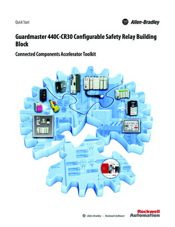
Quick StartGuardmaster 440C-CR30 Configurable Safety Relay BuildingBlockConnected Components Accelerator Toolkit
Important User InformationRead this document and the documents listed in the additional resources section about installation, configuration, andoperation of this equipment before you install, configure, operate, or maintain this product. Users are required tofamiliarize themselves with installation and wiring instructions in addition to requirements of all applicable codes, laws,and standards.Activities including installation, adjustments, putting into service, use, assembly, disassembly, and maintenance are requiredto be carried out by suitably trained personnel in accordance with applicable code of practice.If this equipment is used in a manner not specified by the manufacturer, the protection provided by the equipment may beimpaired.In no event will Rockwell Automation, Inc. be responsible or liable for indirect or consequential damages resulting from theuse or application of this equipment.The examples and diagrams in this manual are included solely for illustrative purposes. Because of the many variables andrequirements associated with any particular installation, Rockwell Automation, Inc. cannot assume responsibility orliability for actual use based on the examples and diagrams.No patent liability is assumed by Rockwell Automation, Inc. with respect to use of information, circuits, equipment, orsoftware described in this manual.Reproduction of the contents of this manual, in whole or in part, without written permission of Rockwell Automation,Inc., is prohibited.Throughout this manual, when necessary, we use notes to make you aware of safety considerations.WARNING: Identifies information about practices or circumstances that can cause an explosion in a hazardous environment,which may lead to personal injury or death, property damage, or economic loss.ATTENTION: Identifies information about practices or circumstances that can lead to personal injury or death, propertydamage, or economic loss. Attentions help you identify a hazard, avoid a hazard, and recognize the consequence.IMPORTANTIdentifies information that is critical for successful application and understanding of the product.Labels may also be on or inside the equipment to provide specific precautions.SHOCK HAZARD: Labels may be on or inside the equipment, for example, a drive or motor, to alert people that dangerousvoltage may be present.BURN HAZARD: Labels may be on or inside the equipment, for example, a drive or motor, to alert people that surfaces mayreach dangerous temperatures.ARC FLASH HAZARD: Labels may be on or inside the equipment, for example, a motor control center, to alert people topotential Arc Flash. Arc Flash will cause severe injury or death. Wear proper Personal Protective Equipment (PPE). Follow ALLRegulatory requirements for safe work practices and for Personal Protective Equipment (PPE).Allen-Bradley, CompactLogix, Connected Components Workbench, Guardmaster, Micro800, Micro820, Micro830, Micro850, PanelView, PowerFlex, ProposalWorks, PS/2, Rockwell Automation, Rockwell Software, andStratix are trademarks of Rockwell Automation, Inc.Trademarks not belonging to Rockwell Automation are property of their respective companies.
Where to StartTo complete your building block project, follow this path.Read the Getting Started CCAT withSystem Design Assistant QuickStart, publication CC-QS035Chapter 1 - Guardmaster 440C-CR30 Configurable Safety Relay SetupChapter 2 - System ValidationRockwell Automation Publication CC-QS038A-EN-P - August 20153
Where to StartNotes:4Rockwell Automation Publication CC-QS038A-EN-P - August 2015
Table of ContentsPrefaceAbout This Publication. . . . . . . . . . . . . . . . . . . . . . . . . . . . . . . . . . . . . . . . . . . . . 7Terminology. . . . . . . . . . . . . . . . . . . . . . . . . . . . . . . . . . . . . . . . . . . . . . . . . . . . . . . 8Available Connected Components Accelerator ToolkitBuilding Blocks . . . . . . . . . . . . . . . . . . . . . . . . . . . . . . . . . . . . . . . . . . . . . . . . . . . . 9Additional Resources . . . . . . . . . . . . . . . . . . . . . . . . . . . . . . . . . . . . . . . . . . . . . . . 9Chapter 1Guardmaster 440C-CR30Configurable Safety Relay SetupBefore You Begin . . . . . . . . . . . . . . . . . . . . . . . . . . . . . . . . . . . . . . . . . . . . . . . .What You Need . . . . . . . . . . . . . . . . . . . . . . . . . . . . . . . . . . . . . . . . . . . . . . . . .Follow These Steps . . . . . . . . . . . . . . . . . . . . . . . . . . . . . . . . . . . . . . . . . . . . . . .Connect the USB Cable to the Safety Relay . . . . . . . . . . . . . . . . . . . . . . . .Configure the Communication Settings . . . . . . . . . . . . . . . . . . . . . . . . . . .Review the 440C-CR30 Software Configurable Safety RelayQuick Start Guide. . . . . . . . . . . . . . . . . . . . . . . . . . . . . . . . . . . . . . . . . . . . . . . .111112131314Chapter 2System ValidationBefore You Begin . . . . . . . . . . . . . . . . . . . . . . . . . . . . . . . . . . . . . . . . . . . . . . . .What You Need . . . . . . . . . . . . . . . . . . . . . . . . . . . . . . . . . . . . . . . . . . . . . . . . .Follow These Steps . . . . . . . . . . . . . . . . . . . . . . . . . . . . . . . . . . . . . . . . . . . . . . .Review the System Overview . . . . . . . . . . . . . . . . . . . . . . . . . . . . . . . . . . . . . .Configure the Controller Communication Ports . . . . . . . . . . . . . . . . . . .Configure the PanelView 800 Terminal Communication Settings. . . .Connect Your Devices. . . . . . . . . . . . . . . . . . . . . . . . . . . . . . . . . . . . . . . . . . . .Download Your Program to the Controller . . . . . . . . . . . . . . . . . . . . . . . .Configure the IP Address of Your PanelView 800 Terminal . . . . . . . . .Transfer Your HMI Application to the PanelView 800 Terminal . . . .Validate Your System. . . . . . . . . . . . . . . . . . . . . . . . . . . . . . . . . . . . . . . . . . . . .Understand the Machine Functions Screen . . . . . . . . . . . . . . . . . . . . .Set Up the Configuration Screen . . . . . . . . . . . . . . . . . . . . . . . . . . . . . .Understand the Status Screen . . . . . . . . . . . . . . . . . . . . . . . . . . . . . . . . .Understand the Fault Screens . . . . . . . . . . . . . . . . . . . . . . . . . . . . . . . . .Verify the Configuration Screens . . . . . . . . . . . . . . . . . . . . . . . . . . . . . .Verify the Status Screen . . . . . . . . . . . . . . . . . . . . . . . . . . . . . . . . . . . . . . .Troubleshoot a Wiring Fault . . . . . . . . . . . . . . . . . . . . . . . . . . . . . . . . . .151516171920222226262828283032333436Appendix A440C-CR30 Configurable Safety Relay . . . . . . . . . . . . . . . . . . . . . . . . . . . . . . . . . . . . . . . . . . . . . . . . . . . . . . . . . . . . . . . . . 39User-defined Function BlockAppendix B. . . . . . . . . . . . . . . . . . . . . . . . . . . . . . . . . . . . . . . . . . . . . . . . . . . . . . . . . . . . . . . . . 43Global VariablesRockwell Automation Publication CC-QS038A-EN-P - August 20155
Table of ContentsNotes:6Rockwell Automation Publication CC-QS038A-EN-P - August 2015
PrefaceAbout This PublicationThe Guardmaster 440C-CR30 configurable safety relay building block monitors the status of the 440C-CR30 safety relaythrough a Modbus RS-232C interface. This quick start provides instructions for how to connect the Micro800 programmable logic controller (PLC) with the safety relay for status updates. Use this quick start to configure a monitoringsystem for your 440C-CR30 safety relay.To help with the design and installation of your system, application files and other information are provided on theConnected Components Accelerator Toolkit (CCAT). The CCAT provides bills of materials (BOM), CAD drawings forpanel layout and wiring, control programs, human machine interface (HMI) screens, and more. With these tools and thebuilt-in best-practices design, you are free to focus on the design of your machine control and not on design overhead tasks.The CCAT is available on the Connected Components Accelerator Toolkit DVD, publication CC-QR002, or throughthe Rockwell Automation Software Download and Registration System (SDRS) site ols/accelerator-toolkit.page.The beginning of each chapter contains the following information. Read these sections carefully before you begin work ineach chapter: Before You Begin - The chapters in this quick start do not have to be completed in the order in which they appear.However, this section defines the minimum amount of preparation that is required before completing the currentchapter. What You Need - This section lists the tools that are required to complete the steps in the current chapter,including, but not limited to, hardware and software. Follow These Steps - This section illustrates the steps in the current chapter and identifies the steps that are requiredto complete the examples.Rockwell Automation Publication CC-QS038A-EN-P - August 20157
PrefaceTerminology8Term (Abbreviation)DefinitionApplication Sequence ProgramsUser-modified programs that work together with the standard-state machine logic to control what the machine doeswhile in the abort, clear, reset, run, and stop states.Auto/manual operationWhen the PanelView 800 terminal is in Auto mode, the controller logic controls the machine and monitors machinestatus.When the PanelView 800 terminal switches to Manual mode, the terminal takes over control. Command buttons andnumeric entry fields are available only when the machine is in Manual mode.Bill of Materials (BOM)A list of components that are needed for your system.Building block (BB)Tools to accelerate and simplify the development of a Micro800 controller-based application. A typical building blockincludes a starting Bill of Material (BOM), Computer-Aided Design (CAD) drawings, Micro800 controller programs,PanelView 800 terminal applications, and a quick start document.Computer-Aided Design (CAD)A computer-based system that is developed to facilitate design of mechanical parts.Connected Components Accelerator Toolkit (CCAT)Software with application files and other information to speed the design and startup of component-based machines.CCAT projectA project that consists of these items: A ProposalWorks -based bill of materials A set of CAD drawings (dimensions and schematics) A Connected Components Workbench project HMI screens A set of Quick Start documents A project document with information about the project components and links to reference materialsConnected Components Workbench softwareSoftware environment for configuring or programming Micro800 controllers, PanelView 800 terminals, PowerFlex drives,and other component-level products.Connected Components Workbench projectA project consists of one or more of the following: Micro800 controller configuration Up to 256 Micro800 programs, each with program local variables Micro800 global variables PanelView 800 terminal application PowerFlex drive parameter listsGlobal variablesProject variables that any program can access, including all I/O and system variables.State Machine control codeMachine logic for coordinating overall machine operation that is based on states. The state machine broadcasts commandsand receives feedback information from each of the building blocks via user-modified application sequence programs.TagsA PanelView 800 term for variables.User-defined Function Blocks (UDFBs)Function block instructions that can be used like standard function block instructions within any Connected ComponentsWorkbench programming language. Anyone that uses Connected Components Workbench software can write thesefunctions blocks. Many UDFBs are posted on the Rockwell Automation sample code dc/groups/public/documents/webassets/sc home page.hcst.User-defined Object (UDO)A collection of PanelView 800 terminal screen objects that can be pasted into a new screen.Rockwell Automation Publication CC-QS038A-EN-P - August 2015
PrefaceAvailable Connected Components Accelerator Toolkit Building BlocksFor the most up-to-date listing of available Connected Components Accelerator Toolkits and related quick starts, refer tothese resources: Rockwell Automation Connected Components Accelerator Toolkit website ols/accelerator-toolkit.page Connected Components Accelerator Toolkit Building Block Project Descriptions Quick Reference,publication CC-QR003Additional ResourcesThese documents contain additional information concerning related products from Rockwell Automation.ResourceDescriptionGuardmaster 440C-CR30 Software Configurable Safety RelayQuick Start Guide, publication 440C-QS001Provides information on how to configure a Guardmaster 440C-CR30 configurable safety relay to communicatewith a PanelView 800 terminal via Modbus communication protocol.Guardmaster 440C-CR30 Configurable Safety Relay User Manual,publication 440C-UM001Provides detailed information on how to install, configure, operate, and troubleshoot a Guardmaster 440C-CR30configurable safety relay.Micro830 and Micro850 Programmable Controllers User Manual,publication 2080-UM002Provides a reference guide for Micro830 and Micro850 controller systems. This publication also containsprocedures on how to install, wire, and troubleshoot your controller.Micro800 Digital and Analog Plug-in Modules and AccessoriesUser Manual, publication 2080-UM004Provides an overview and procedures for installing, wiring, and troubleshooting Micro800 plug-in modules andaccessories.Micro820 20-point Programmable Controllers User Manual,publication 2080-UM005Provides a reference guide for Micro820 controller systems. It also contains procedures on how to install, wire,and troubleshoot your controller.PanelView 800 HMI Terminals User Manual, publication2711R-UM001Provides information for configuring the PanelView 800 terminal.PanelView 800 HMI Terminals Installation Instructions,publication 2711R-IN001Provides instructions on how to install, wire, ground, and troubleshoot PanelView 800 terminals.You can view or download publications at http://www.rockwellautomation.com/literature/. To order paper copies oftechnical documentation, contact your local Allen-Bradley distributor or Rockwell Automation sales representative.Rockwell Automation Publication CC-QS038A-EN-P - August 20159
PrefaceNotes:10Rockwell Automation Publication CC-QS038A-EN-P - August 2015
Chapter1Guardmaster 440C-CR30 Configurable Safety Relay SetupThis chapter provides information for how to configure the hardware for the 440C-CR30 safety relay.Before You Begin Review the Getting Started Connected Components Accelerator Toolkit with System Design Assistant Quick Start,publication CC-QS035. Apply power to your 440C-CR30 safety relay.What You Need Personal computer with an available USB port440C-CR30-22BBB safety relayUSB cable (for programming the safety relay)Connected Components Workbench software, version 8.00Rockwell Automation Publication CC-QS038A-EN-P - August 201511
Chapter 1Guardmaster 440C-CR30 Configurable Safety Relay SetupFollow These StepsTo configure your 440C-CR30 safety relay, complete these steps.StartConnect the USB Cable to theSafety Relay on page 13Configure the CommunicationSettings on page 13Review the 440C-CR30 SoftwareConfigurable Safety Relay QuickStart Guide on page 1412Rockwell Automation Publication CC-QS038A-EN-P - August 2015
Guardmaster 440C-CR30 Configurable Safety Relay SetupChapter 1Connect the USB Cable to the Safety RelayConnect a USB cable between the safety relay and your personal computer. The driver for the safety relay is automaticallyinstalled. If the driver did not install, unplug the USB cable and plug it in again.Figure 1 - Connect the Safety Relay to Your ComputerConfigure the Communication SettingsTo configure the safety relay communication settings for the Micro800 controller, follow these steps.1. Launch the Connected Component Workbench version 8 software.2. To add the 440C-CR30 safety relay to your project, from the Device Tool box open Catalog Safety anddouble-click the 440C-CR30 safety relay.3. In the project organizer, double-click the safety relay.Rockwell Automation Publication CC-QS038A-EN-P - August 201513
Chapter 1Guardmaster 440C-CR30 Configurable Safety Relay Setup4. To configure the communication parameters, select Serial Port.5. From the Common Settings pull-down menu lists, choose these options: Driver: Modbus RTU Baud Rate: 19200 Parity: None6. Download the configuration to the safety relay.7. Select the device from the connection browser and click OK to begin download.Review the 440C-CR30 Software Configurable Safety Relay Quick Start GuideFollow the instructions in the 440C-CR30 Software Configurable Safety Relay Quick Start Guide,publication 440C-QS001, to configure the safety relay.14Rockwell Automation Publication CC-QS038A-EN-P - August 2015
Chapter2System ValidationThis chapter provides information for how to configure the controller and human machine interface (HMI) so the devicesare communicating correctly. After the configuration is complete, you can validate the system for monitoring the status ofthe 440C-CR30 safety relay.Before You Begin Complete the steps in Chapter 1. Verify that the devices are connected as shown in the wiring diagrams (see Figure 2, Figure 3, or Figure 4). Apply power to the devices.What You Need Micro800 controller440C-CR30-22BBB safety relay4-inch or larger PanelView 800 terminalStratix Ethernet switch (if you use a CIP-on-Ethernet connection)One pair of 1761-CBL-HM02 cablesThree pairs of USB programming cables (A to B) or Ethernet cables for personal computer to Micro800 controllercommunication Personal computer with available USB port and Ethernet connection with Connected Components Workbenchsoftware, version 8.00, installedRockwell Automation Publication CC-QS038A-EN-P - August 201515
Chapter 2System ValidationFollow These StepsTo validate your system, complete these steps.Start16Review the SystemOverview on page 17Download Your Program to theController on page 22Configure the ControllerCommunication Ports on page 19Configure the IP Address of YourPanelView 800 Terminal on page 26Configure the PanelView 800Terminal Communication Settingson page 20Transfer Your HMI Applicationto the PanelView 800 Terminalon page 26Connect Your Devices on page 22Validate Your System on page 28Rockwell Automation Publication CC-QS038A-EN-P - August 2015
System ValidationChapter 2Review the System OverviewThe PanelView 800 Graphic Terminal can be connected to the Micro800 controller with a CIP serial or CIP-on-Ethernetconnection: For a CIP serial connection, use a 1761-CBL-PM02 cable to connect the PanelView 800 terminal to the embeddedserial port of the Micro800 controller. For a CIP-on-Ethernet connection, connect the PanelView 800 terminal to the Stratix Ethernet switch. Then use theEthernet patch cords to connect the Stratix Ethernet switch to the embedded Ethernet port of the Micro800controller. For a CIP-on-Ethernet connection to a Micro850 controller, you can connect the terminal directly to the Ethernetport on the Micro850 controller by using an Ethernet cable.All connection methods are explained in this manual, but choose only one method for your project.The 440C-CR30 safety relay can be connected directly to the embedded serial port of the Micro800. The safety relay canalso be connected to a serial plug-in module when the embedded serial port is already configured to communicate with aPanelView 800 terminal.Figure 2 - Connection for Micro820 and 440C-CR30 Safety Relay With a Modified 1761-CBL-HM02 CableIP Address: 192.168.1.2Modified 1761-CBL-HM02EthernetCableMicro820IP Address: 192.168.1.3440C-CR30 Safety RelayTo modify the 1761-CBL-HM02 cable, follow these steps.1. Cut the 1761-CBL-HM02 cable to the required length.2. Identify the wire that is connected to pins 2, 4, and 7 of the PS/2 connector.3. Connect the wire to the respective terminal according to this table.Rockwell Automation Publication CC-QS038A-EN-P - August 201517
Chapter 2System Validation440C-CR30 Safety Relay ConnectorMicro800 Controller TerminalPin 7RxPin 4TxPin 2GFigure 3 - Connection for Micro850 and 440C-CR30 Safety RelayIP Address: 192.168.1.2Micro850IP Address: 192.168.1.3EthernetCable440C-CR30 Safety Relay1761-CBL-HM02Figure 4 - Connection for Micro830 and 440C-CR30 Safety RelayMicro8301761-CBL-PM02440C-CR30 Safety RelayModified 1761-CBL-HM0218Rockwell Automation Publication CC-QS038A-EN-P - August 2015
System ValidationChapter 2Configure the Controller Communication PortsBy default, the 440C-CR30 safety relay serial communication port has these communication settings.Figure 5 - Default Communication Configuration for the 440C-CR30 Safety RelayTo communicate with the 440C-CR30 safety relay, you must configure the embedded serial port or serial plug-in moduleof the Micro800 controller with these configuration settings.Figure 6 - Embedded Serial Port Settings for the Micro800 ControllerRockwell Automation Publication CC-QS038A-EN-P - August 201519
Chapter 2System ValidationConfigure the PanelView 800 Terminal Communication SettingsTo modify these settings in the default Connected Components Workbench project, follow these steps.1. To open the PanelView 800 application editor, in the Project Organizer double-click the PanelView 800 device icon.The PanelView 800 Communication Settings pane appears in the main project window.2. Configure the appropriate communication settings:For CIP Serial communication, configure the settings that are shown here.20Rockwell Automation Publication CC-QS038A-EN-P - August 2015
System ValidationChapter 2For CIP-on-Ethernet communication, configure the settings that are shown here.Rockwell Automation Publication CC-QS038A-EN-P - August 201521
Chapter 2System ValidationConnect Your DevicesThere are three network layouts that are identified in Review the System Overview on page 17. In this Quick Start, wepicked the Connection with CIP-Ethernet for our application example.Figure 7 - Device ConnectionsIP Address: 192.168.1.2IP Address: 192.168.1.3EthernetCable440C-CR30 Safety Relay1761-CBL-HM02Download Your Program to the ControllerTo download your program to the controller, follow these steps.1. Connect your personal computer to the controller (use either an Ethernet or USB connection).If you are prompted to install any drivers, install the recommended drivers.22Rockwell Automation Publication CC-QS038A-EN-P - August 2015
System ValidationChapter 2To modify the settings for the project that are generated from CCAT version 2 or the projectStarting CR30 M800 r8 downloaded from the Rockwell Automation sample code website, follow these steps.2. From the project organizer, open the local variables of device name M800 CR30 Sts.3. Search for Channel in local variable list.4. Update the initial value of the variable to the channel number of your serial communication port regarding the portlocation. In this example, we use the embedded serial communication port (channel 2).Channel 2Channel 5Channel 6Channel 7Rockwell Automation Publication CC-QS038A-EN-P - August 201523
Chapter 2System Validation5. In your Connected Components Workbench project, from the Project Organizer, right-click your controller iconand choose Build.6. When the program is finished building, check the Output pane at the bottom of your project window for a buildsuccess message.Example Output Pane: Build SuccessfulIf the build is successful, continue to step 7.If the build is unsuccessful, an errors list appears. Continue to step a.Example Output Pane: Error Lista. Double-click an error description to go to that error.b. Correct each error.c. Repeat step 2 step 6 until the build is successful and continue to step 7.7. From the Project Organizer, right-click your controller icon and choose Download.24Rockwell Automation Publication CC-QS038A-EN-P - August 2015
System ValidationChapter 28. From the Connection Browser, select your controller and click OK. For USB connection. For Ethernet connection.9. If prompted to change the controller mode to Remote Program mode, click Yes.Rockwell Automation Publication CC-QS038A-EN-P - August 201525
Chapter 2System ValidationConfigure the IP Address of Your PanelView 800 TerminalTo configure a static IP address on the PanelView 800 terminal, follow these steps.1. From the Main menu, press Communication to open the Communication screen.2. Press Set Static IP Address.3. Configure the IP Address and Mask values so that they are in the same range as your Micro800 controller.For example, in this Quick Start, we set the IP address of the PanelView terminal to 192.168.100.2.4. To return to the Main menu, press Main.Transfer Your HMI Application to the PanelView 800 TerminalTo transfer your HMI application to the PanelView 800 terminal by using Connected Components Workbench software,follow these steps.1. Be sure that your PanelView 800 terminal is connected with your personal computer via an Ethernet switch orEthernet cable.2. In the Project Organizer, right-click the PanelView 800 device icon and choose Download.The Connection Browser window appears.26Rockwell Automation Publication CC-QS038A-EN-P - August 2015
System ValidationChapter 23. Select the PanelView 800 terminal and click OK.4. Verify that the download completed successfully.5. From the Main menu of your PanelView 800 terminal, press File Manager.6. On the File Manager screen, select Internal as your Source.7. Select your application CR30 T6T M800 ETNEIP r8.8. Press Run.Rockwell Automation Publication CC-QS038A-EN-P - August 201527
Chapter 2System ValidationValidate Your SystemIn this section, you review the Machine Functions screen and explore the Status and Command screens to test the manualcontrol of the building block.Understand the Machine Functions ScreenThe Machine Functions screen is the screen that links to the installed building blocks. When this screen is first loaded, youcan complete the following tasks: Return to the Machine Overview screen by pressing the X in the upper right-hand corner of the screen. View a device in detail by pressing its button. View the current machine Auto/Manual state. Change the current machine Auto/Manual state. Clear machine faults, start/stop the machine (while in Auto mode), and go to the machine state diagram overviewscreen.The border of the device button changes color to indicate a specific status. For the 440C-CR30 safety relay, the buttonborder colors indicate the following status: A green border indicates that the safety relay is active and operating. A gray border indicates that the safety relay is inactive and stopped. A red border indicates that there is a fault, or an alarm is present.Set Up the Configuration ScreenTo set up the 440C-CR30: Configure IO Description screen, follow these steps.1. From the Machine Functions screen, switch the Operation mode toManual.2. Press the device.The Configuration screen for the device appears. There are a total of fourconfiguration screens.3. Type the name of each terminal of the 440C-CR30 safety relay.There are a total of 22 embedded terminals and two plug-in terminals.4. Record a description of each connection in the table on the next page.28Rockwell Automation Publication CC-QS038A-EN-P - August 2015
System ValidationTerminal NameChapter 2Enter a description of the connection or the name of the safety device that is connected to the corresponding terminal.IN 0IN 1IN 2IN 3IN 4IN 5IN 6IN 7IN 8IN 9IN 10IN 11IO 12IO 13IO 14IO 15IO 16IO 17OUT 18OUT 19OUT 20OUT 21Plugin Slot 1- IN 1Plugin Slot 1- IN 2Plugin Slot 1- IN 3Plugin Slot 1- IN 4Plugin Slot 1- OUT 1Plugin Slot 1- OUT 2Plugin Slot 1- OUT 3Plugin Slot 1- OUT 4Plugin Slot 2- IN 1Plugin Slot 2- IN 2Plugin Slot 2- IN 3Plugin Slot 2- IN 4Plugin Slot 2- OUT 1Plugin Slot 2- OUT 2Plugin Slot 2- OUT 3Plugin Slot 2- OUT 4Rockwell Automation Publication CC-QS038A-EN-P - August 201529
Chapter 2System Validation5. At any time, press X in the top-right corner to return to the previous screen and press the Next page button toconfigure the terminals on the next page.6. When you arrived at the last configuration page, press the Config Done button.The IO Sts page button appears.7. To go to the Status screen, press the IO Sts page button.8. If you want to change the names again, press the Edit Config button.Understand the Status ScreenThere are a total of four status screens. They represent terminal status for embedded terminals 0 21 and the plug-inmodule that is attached to plug-in slot 1 and slot 2.See Table 1 on page 31 for a description of the status indicators.30Rockwell Automation Publication CC-QS038A-EN-P - August 2015
System ValidationChapter 2Table 1 - 440C-CR30 Safety Relay Status IndicatorsTerminal NameRedGrayGreenThe respective terminal is notactivated.The respective terminal is activated.IN 0IN 1IN 2IN 3IN 4IN 5IN 6Not applicable.IN 7IN 8IN 9IN 10IN 11IO 12IO 13IO 14IO 15A cross fault occurred at the respectiveterminal.IO 16IO 17OUT 18OUT 19OUT 20OUT 21Plugin Slot 1- IN 1Plugin Slot 1- IN 2Plugin Slot 1- IN 3Plugin Slot 1- IN 4Plugin Slot 1- OUT 1Plugin Slot 1- OUT 2Plugin Slot 1- OUT 3Not applicable.Plugin Slot 1- OUT 4Plugin Slot 2- IN 1Plugin Slot 2- IN 2Plugin Slot 2- IN 3Plugin Slot 2- IN 4Plugin Slot 2- OUT 1Plugin Slot 2- OUT 2Plugin Slot 2- OUT 3Plugin Slot 2- OUT 4Rockwell Automation Publication CC-QS038A-EN-P - August 201531
Chapter 2System ValidationUnderstand the Fault ScreensThere are two types
Guardmaster 440C-CR30 Configurable Safety Relay Setup This chapter provides information for how to configure the hardware for the 440C-CR30 safety relay. Before You Begin Review the Getting Started Connected Components Accelerator Toolkit with System Design Assistant Quick Start, publication CC-QS035. Apply power to your 440C-CR30 .