Transcription
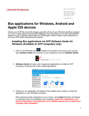
WHAT’S IN THIS BOX880FE-StopUSB ProgrammingCableMountingPlate440NSensaGuardScrews WashersPVC E-StopCable700-HPRelays SocketsPowerSupplyGuardMaster CR30Safety RelayFlash Drive:Software Manuals2080 Digital I/OPlug-InOPTIONAL PRODUCTSTo put together advanced demos, purchase separatelyEtherNet Plug-InPanelView ComponentReset Button
WHAT YOU NEEDThese are not included. Gather these items first:MultimeterPower CordWire StrippersScrew DriversCable Cutters16 or 18 AWG WireLaptopDIN Rail
440C-CR30 HARDWARE CONFIGURATION GUIDESTEP 1 Using the Flash Drive, Download Connected Components Workbench (CCW) onto your laptop.Let the installation run in the background, this could take a little time.Download CCWNOTE Flash Drive also has manuals, datasheets, and more!Installation InstructionsUser ManualQuick StartGuide
STEP 2 Mount DIN rail onto mounting plate with screws and washers.STEP 3 Mount power supply, CR30, and both relays onto DIN rail.STEP 4 Insert the 2080 Digital I/O Plug-in into Slot 1 of the 440C-CR30
STEP 5 Wire the following according to the wiring diagram: 440C-CR30700-HP RelaysPower supplyEmergency-stopSensaGuard2080 Digital I/O PluginSTEP 6 When the CCW installation is complete, follow the “Configuring the CR30 with Software”instructions on the next page.
CONFIGURING THE CR30 WITH SOFTWAREThe 440C-CR30 is configured with Connected Components Workbench software.Let’s go through the following steps to:a.b.c.d.create a projectdownload it,verify the project for safety purposescreate a report.STEP 1 Open Connected Components Workbench with the Start menu on your desktop
STEP 2 Create a new projectSTEP 3 Select the firmware revision inside the CR30 to match the project revisionNOTE Refer to the “ControlFlash Update and Flashing” document on the flash drive on how tochange the firmware inside the CR30.
STEP 4 Open the CR30 EditorNOTE The Manual and Help buttons can assist you throughout your projectSTEP 5 Add the 2080 I/O Plug-In
STEP 6 Open the Logic EditorSTEP 7 Add the existing hardware by dragging and dropping from the Toolbox
STEP 8 Configure the Feedback block’s inputs
STEP 9 Drag the AND fuction block in the Logic Level A columnSTEP 10 Add the Immediate OFF function block for the Safety Output
STEP 11 Configure the Immediate OFF function block’s feedback and reset
STEP 12 Wire the function blocks together (click the blue circles)
NOTE This is what the final it should look like!
STEP 13 Build the projectSTEP 14 Download the project to the 440C-CR30 relay
STEP 15 Verify the project for safety purposes
STEP 16 Create a report
Congrats! You have just put together a CR30 project. Test out your logic by pushing theEmergency-Stop or pulling the SensaGuard apart.
GuardMaster CR30 Safety Relay 2080 Digital I/O Plug-In 440N SensaGuard EtherNet Plug-In . WHAT YOU NEED These are not included. Gather these items first: . STEP 14 Download the project to the 440C-CR30 relay . STEP 15 Verify the project for safety purposes . STEP 16 Create a report. Congrats! You have just put together a CR30 project. Test .