Transcription
User ManualOriginal InstructionsGuardmaster Safety RelaysCatalog Numbers 440R-S13R2, 440R-S12R2, 440R-D22R2, 440R-D22S2, 440R-EM4R2, 440R-EM4R2D
Important User InformationRead this document and the documents listed in the additional resources section about installation, configuration, andoperation of this equipment before you install, configure, operate, or maintain this product. Users are required tofamiliarize themselves with installation and wiring instructions in addition to requirements of all applicable codes, laws,and standards.Activities including installation, adjustments, putting into service, use, assembly, disassembly, and maintenance arerequired to be carried out by suitably trained personnel in accordance with applicable code of practice.If this equipment is used in a manner not specified by the manufacturer, the protection provided by the equipment maybe impaired.In no event will Rockwell Automation, Inc. be responsible or liable for indirect or consequential damages resulting fromthe use or application of this equipment.The examples and diagrams in this manual are included solely for illustrative purposes. Because of the many variables andrequirements associated with any particular installation, Rockwell Automation, Inc. cannot assume responsibility orliability for actual use based on the examples and diagrams.No patent liability is assumed by Rockwell Automation, Inc. with respect to use of information, circuits, equipment, orsoftware described in this manual.Reproduction of the contents of this manual, in whole or in part, without written permission of Rockwell Automation,Inc., is prohibitedThroughout this manual, when necessary, we use notes to make you aware of safety considerations.WARNING: Identifies information about practices or circumstances that can cause an explosion in a hazardousenvironment, which may lead to personal injury or death, property damage, or economic loss.ATTENTION: Identifies information about practices or circumstances that can lead to personal injury or death, propertydamage, or economic loss. Attentions help you identify a hazard, avoid a hazard, and recognize the consequence.IMPORTANTIdentifies information that is critical for successful application and understanding of the product.Labels may also be on or inside the equipment to provide specific precautions.SHOCK HAZARD: Labels may be on or inside the equipment, for example, a drive or motor, to alert people that dangerousvoltage may be present.BURN HAZARD: Labels may be on or inside the equipment, for example, a drive or motor, to alert people that surfaces mayreach dangerous temperatures.ARC FLASH HAZARD: Labels may be on or inside the equipment, for example, a motor control center, to alert people topotential Arc Flash. Arc Flash will cause severe injury or death. Wear proper Personal Protective Equipment (PPE). Follow ALLRegulatory requirements for safe work practices and for Personal Protective Equipment (PPE).
Table of ContentsPrefaceSummary of Changes . . . . . . . . . . . . . . . . . . . . . . . . . . . . . . . . . . . . . . . . . . .Who Should Use This Manual? . . . . . . . . . . . . . . . . . . . . . . . . . . . . . . . . .Additional Resources . . . . . . . . . . . . . . . . . . . . . . . . . . . . . . . . . . . . . . . . . . .Definitions . . . . . . . . . . . . . . . . . . . . . . . . . . . . . . . . . . . . . . . . . . . . . . . . . . . .7778Chapter 1OverviewHardware Features . . . . . . . . . . . . . . . . . . . . . . . . . . . . . . . . . . . . . . . . . . . . . 9Removable Terminal Blocks . . . . . . . . . . . . . . . . . . . . . . . . . . . . . . . . . 9Status Indicators. . . . . . . . . . . . . . . . . . . . . . . . . . . . . . . . . . . . . . . . . . . . 9Multi-position Switches. . . . . . . . . . . . . . . . . . . . . . . . . . . . . . . . . . . . 10Optical Communication Bus . . . . . . . . . . . . . . . . . . . . . . . . . . . . . . . 10CI Safety Relay (Cat. No. 440R-S13R2). . . . . . . . . . . . . . . . . . . . . . . . . 10DI Safety Relay (Cat. No. 440R-D22R2) . . . . . . . . . . . . . . . . . . . . . . . . 10DIS Safety Relay (Cat. No. 440R-D22S2) . . . . . . . . . . . . . . . . . . . . . . . 10EM Safety Relay (Cat. No. 440R-EM4R2) . . . . . . . . . . . . . . . . . . . . . . 11EMD Safety Relay (Cat. No. 440R-EM4R2D). . . . . . . . . . . . . . . . . . . 11SI Safety Relay (Cat. No. 440R-S12R2) . . . . . . . . . . . . . . . . . . . . . . . . . 11Chapter 2InstallationMounting Dimensions. . . . . . . . . . . . . . . . . . . . . . . . . . . . . . . . . . . . . . . . .DIN Rail Mounting and Removal . . . . . . . . . . . . . . . . . . . . . . . . . . . . . .Removal . . . . . . . . . . . . . . . . . . . . . . . . . . . . . . . . . . . . . . . . . . . . . . . . . .Spacing . . . . . . . . . . . . . . . . . . . . . . . . . . . . . . . . . . . . . . . . . . . . . . . . . . .Removable Terminals. . . . . . . . . . . . . . . . . . . . . . . . . . . . . . . . . . . . . . . . . .Enclosure Considerations . . . . . . . . . . . . . . . . . . . . . . . . . . . . . . . . . . . . . .Prevent Excessive Heat . . . . . . . . . . . . . . . . . . . . . . . . . . . . . . . . . . . . . . . .13131314141415Chapter 3Power, Ground, and WireWiring Requirements and Recommendation . . . . . . . . . . . . . . . . . . . .Wire Size . . . . . . . . . . . . . . . . . . . . . . . . . . . . . . . . . . . . . . . . . . . . . . . . .Terminal Torque . . . . . . . . . . . . . . . . . . . . . . . . . . . . . . . . . . . . . . . . . .Terminal Assignments . . . . . . . . . . . . . . . . . . . . . . . . . . . . . . . . . . . . .Ground the Relay . . . . . . . . . . . . . . . . . . . . . . . . . . . . . . . . . . . . . . . . . . . . .Connect a Power Supply . . . . . . . . . . . . . . . . . . . . . . . . . . . . . . . . . . . . . . .Safety Inputs. . . . . . . . . . . . . . . . . . . . . . . . . . . . . . . . . . . . . . . . . . . . . . . . . .Devices with Mechanical Contacts . . . . . . . . . . . . . . . . . . . . . . . . . .Safety Devices with OSSD Outputs . . . . . . . . . . . . . . . . . . . . . . . . .Safety Mats . . . . . . . . . . . . . . . . . . . . . . . . . . . . . . . . . . . . . . . . . . . . . . .Safety Outputs . . . . . . . . . . . . . . . . . . . . . . . . . . . . . . . . . . . . . . . . . . . . . . . .Electromechanical Outputs. . . . . . . . . . . . . . . . . . . . . . . . . . . . . . . . .OSSD Outputs. . . . . . . . . . . . . . . . . . . . . . . . . . . . . . . . . . . . . . . . . . . .Surge Suppressors. . . . . . . . . . . . . . . . . . . . . . . . . . . . . . . . . . . . . . . . . .Single Wire Safety Input and Output . . . . . . . . . . . . . . . . . . . . . . . . . . .Auxiliary Output. . . . . . . . . . . . . . . . . . . . . . . . . . . . . . . . . . . . . . . . . . . . . .Reset and Monitor Input . . . . . . . . . . . . . . . . . . . . . . . . . . . . . . . . . . . . . .Automatic/Manual Reset . . . . . . . . . . . . . . . . . . . . . . . . . . . . . . . . . .Monitored Reset . . . . . . . . . . . . . . . . . . . . . . . . . . . . . . . . . . . . . . . . . .Monitor with Expansion Relays. . . . . . . . . . . . . . . . . . . . . . . . . . . . .Retriggerable Input . . . . . . . . . . . . . . . . . . . . . . . . . . . . . . . . . . . . . . . . . . . .Jog Input . . . . . . . . . . . . . . . . . . . . . . . . . . . . . . . . . . . . . . . . . . . . . . . . . . . . .Rockwell Automation Publication 440R-UM013D-EN-P - December 2016171717181919202021232424242526272727282929293
Table of ContentsChapter 4ConfigurationSwitch Adjustment . . . . . . . . . . . . . . . . . . . . . . . . . . . . . . . . . . . . . . . . . . . .DI and DIS Safety Relays. . . . . . . . . . . . . . . . . . . . . . . . . . . . . . . . . . .EMD Safety Relay . . . . . . . . . . . . . . . . . . . . . . . . . . . . . . . . . . . . . . . . .Configuration Process . . . . . . . . . . . . . . . . . . . . . . . . . . . . . . . . . . . . . . . . .1. Prepare the Switch . . . . . . . . . . . . . . . . . . . . . . . . . . . . . . . . . . . . . .2. Apply Power . . . . . . . . . . . . . . . . . . . . . . . . . . . . . . . . . . . . . . . . . . . .3. Adjust the Switch . . . . . . . . . . . . . . . . . . . . . . . . . . . . . . . . . . . . . . .4. Verify the Settings . . . . . . . . . . . . . . . . . . . . . . . . . . . . . . . . . . . . . . .5. Cycle the Power . . . . . . . . . . . . . . . . . . . . . . . . . . . . . . . . . . . . . . . . .323233343434343535Chapter 5Status Indicators andTroubleshootingIndicators During Powerup . . . . . . . . . . . . . . . . . . . . . . . . . . . . . . . . . . . . 37Indicators During Normal Operation . . . . . . . . . . . . . . . . . . . . . . . . . . . 37Indicators During Diagnostics. . . . . . . . . . . . . . . . . . . . . . . . . . . . . . . . . . 38Chapter 6Pulse Testing FunctionsPulse Testing for Inputs. . . . . . . . . . . . . . . . . . . . . . . . . . . . . . . . . . . . . . . .CI Safety Relay . . . . . . . . . . . . . . . . . . . . . . . . . . . . . . . . . . . . . . . . . . . .DI, DIS, and SI Safety Relays . . . . . . . . . . . . . . . . . . . . . . . . . . . . . . .Pulse Testing for OSSD Outputs . . . . . . . . . . . . . . . . . . . . . . . . . . . . . . .39394040Chapter 7EMD Safety Relay TimingFunctionsOff Delay, Non-retriggerable . . . . . . . . . . . . . . . . . . . . . . . . . . . . . . . . . . .Case 1 . . . . . . . . . . . . . . . . . . . . . . . . . . . . . . . . . . . . . . . . . . . . . . . . . . . .Case 2 . . . . . . . . . . . . . . . . . . . . . . . . . . . . . . . . . . . . . . . . . . . . . . . . . . . .Case 3 . . . . . . . . . . . . . . . . . . . . . . . . . . . . . . . . . . . . . . . . . . . . . . . . . . . .Off Delay, Retriggerable . . . . . . . . . . . . . . . . . . . . . . . . . . . . . . . . . . . . . . .Case 1 . . . . . . . . . . . . . . . . . . . . . . . . . . . . . . . . . . . . . . . . . . . . . . . . . . . .Case 2 . . . . . . . . . . . . . . . . . . . . . . . . . . . . . . . . . . . . . . . . . . . . . . . . . . . .On Delay . . . . . . . . . . . . . . . . . . . . . . . . . . . . . . . . . . . . . . . . . . . . . . . . . . . . .Case 1 . . . . . . . . . . . . . . . . . . . . . . . . . . . . . . . . . . . . . . . . . . . . . . . . . . . .Case 2 . . . . . . . . . . . . . . . . . . . . . . . . . . . . . . . . . . . . . . . . . . . . . . . . . . . .Jog . . . . . . . . . . . . . . . . . . . . . . . . . . . . . . . . . . . . . . . . . . . . . . . . . . . . . . . . . . .Case 1 . . . . . . . . . . . . . . . . . . . . . . . . . . . . . . . . . . . . . . . . . . . . . . . . . . . .Case 2 . . . . . . . . . . . . . . . . . . . . . . . . . . . . . . . . . . . . . . . . . . . . . . . . . . . .Case 3 . . . . . . . . . . . . . . . . . . . . . . . . . . . . . . . . . . . . . . . . . . . . . . . . . . . .4141424242424343434344444445Chapter 8Internal Circuit Block Diagrams4CI Safety Relay (Cat. No. 440R-S13R2). . . . . . . . . . . . . . . . . . . . . . . . .DI Safety Relay (Cat. No. 440R-D22R2) . . . . . . . . . . . . . . . . . . . . . . . .DIS Safety Relay (Cat. No. 440R-D22S2) . . . . . . . . . . . . . . . . . . . . . . .EM Safety Relay (Cat. No. 440R-EM4R2) . . . . . . . . . . . . . . . . . . . . . .EMD Safety Relay (Cat. No. 440R-EM4R2D). . . . . . . . . . . . . . . . . . .SI Safety Relay (Cat. No. 440R-S12R2) . . . . . . . . . . . . . . . . . . . . . . . . .Rockwell Automation Publication 440R-UM013D-EN-P - December 2016474747484848
Table of ContentsChapter 9Application and Wiring Examples CI Safety Relay (Cat. No. 440R-S13R2). . . . . . . . . . . . . . . . . . . . . . . . . 49DI Safety Relay (Cat. No. 440R-D22R2) . . . . . . . . . . . . . . . . . . . . . . . .DIS Safety Relay (Cat. No. 440R-D22S2) . . . . . . . . . . . . . . . . . . . . . . .EM Safety Relay (Cat. No. 440R-EM4R2) . . . . . . . . . . . . . . . . . . . . . .EMD Safety Relay (Cat. No. 440R-EM4R2D). . . . . . . . . . . . . . . . . . .SI Safety Relay (Cat. No. 440R-S12R2) . . . . . . . . . . . . . . . . . . . . . . . . .5051525354Chapter 10Ethernet CommunicationWeb Page. . . . . . . . . . . . . . . . . . . . . . . . . . . . . . . . . . . . . . . . . . . . . . . . . . . . . 56Studio 5000 Logix Designer Add-on Profile (AOP) . . . . . . . . . . . . . . 56Appendix ASpecificationsGeneral. . . . . . . . . . . . . . . . . . . . . . . . . . . . . . . . . . . . . . . . . . . . . . . . . . . . . . .Environmental . . . . . . . . . . . . . . . . . . . . . . . . . . . . . . . . . . . . . . . . . . . . . . . .Safety Inputs IN, IN1, and IN2. . . . . . . . . . . . . . . . . . . . . . . . . . . . . . . . .Reset Input . . . . . . . . . . . . . . . . . . . . . . . . . . . . . . . . . . . . . . . . . . . . . . . . . . .B1 Input. . . . . . . . . . . . . . . . . . . . . . . . . . . . . . . . . . . . . . . . . . . . . . . . . . . . . .Safety Outputs . . . . . . . . . . . . . . . . . . . . . . . . . . . . . . . . . . . . . . . . . . . . . . . .Auxiliary Output. . . . . . . . . . . . . . . . . . . . . . . . . . . . . . . . . . . . . . . . . . . . . .Single Wire Safety . . . . . . . . . . . . . . . . . . . . . . . . . . . . . . . . . . . . . . . . . . . . .5757585859596060Appendix BRegulatory ApprovalsAgency Certifications. . . . . . . . . . . . . . . . . . . . . . . . . . . . . . . . . . . . . . . . . .Compliance to European Union Directives. . . . . . . . . . . . . . . . . . . . . .EMC Directive . . . . . . . . . . . . . . . . . . . . . . . . . . . . . . . . . . . . . . . . . . . .Machine Safety Directive. . . . . . . . . . . . . . . . . . . . . . . . . . . . . . . . . . .SIL Rating . . . . . . . . . . . . . . . . . . . . . . . . . . . . . . . . . . . . . . . . . . . . . . . .Performance Level/Category . . . . . . . . . . . . . . . . . . . . . . . . . . . . . . .616161616262Index . . . . . . . . . . . . . . . . . . . . . . . . . . . . . . . . . . . . . . . . . . . . . . . . . . . . . . . .63Rockwell Automation Publication 440R-UM013D-EN-P - December 20165
Table of ContentsNotes:6Rockwell Automation Publication 440R-UM013D-EN-P - December 2016
PrefaceThis manual is a reference guide for the family of Guardmaster Safety Relays(GSR). It describes the procedures that you use to install, wire, andtroubleshoot your relay. This manual also gives an overview of the operation ofsafety relays.Summary of ChangesThis manual contains new and updated information. We added anintroductory paragraph to the Configuration chapter on page 31.Who Should Use ThisManual?Use this manual if your responsibilities include design, installation,programming, or troubleshooting of control systems that use safety relays,including catalog numbers: 440R-S13R2 (CI) 440R-D22R2 (DI) 440R-D22S2 (DIS) 440R-EM4R2 (EM) 440R-EM4R2D (EMD) 440R-S12R2 (SI)You must have a basic understanding of electrical circuitry and familiarity withsafety-related control systems. If you do not have this knowledge, obtain theproper training before using this product.Additional ResourcesThese documents contain additional information concerning related productsfrom Rockwell Automation.ResourceDescriptionGuardmaster EtherNet/IP Network Interface User Manual,publication 440R-UM009Describes procedures that you use to install, wire,configure, troubleshoot, and use EtherNet/IPmodules.Industrial Automation Wiring and Grounding Guidelines,publication 1770-4.1Provides general guidelines for installing a RockwellAutomation industrial system.Product Certifications website, tion/overview.pageProvides declarations of conformity, certificates, andother certification details.You can view or download publications ure-library/overview.page.To order paper copies of technical documentation, contact your localAllen-Bradley distributor or Rockwell Automation sales representative.Rockwell Automation Publication 440R-UM013D-EN-P - December 20167
PrefaceDefinitionsPublication AG-7.1 contains a glossary of terms and abbreviations that areused by Rockwell Automation to describe industrial automation systems. Thefollowing is a list of specific terms and abbreviations that are used in thismanual. N.C. (Normally Closed) - An electrical contact whose normal state isin the closed position. N.O. (Normally Open) - An electrical contact whose normal state is inthe open position. PLC - A programmable logic controller or a programmable automationcontroller. Reaction Time - The time between the true states of one input to theON state of the output. Recovery Time - The time that is required for the input to be in the LOstate before returning to the HI state. Reset - Safety relays offer two types of reset: monitored manual andautomatic/manual.– Monitored Manual - The safety relay performs a reset function whenthe reset signal goes from OFF to ON and then back to OFF in aprescribed time-period. The reset occurs on the trailing edge.– Automatic/Manual - The safety relay performs a reset function ifthe reset input is ON. If the reset input is connected directly to 24V,the reset function is executed immediately when the inputs becomeclosed or active. If a contact (push button or equivalent device) isused in the reset input, the reset function is executed on the leadingedge of the reset signal (if the inputs are closed or active). Response Time - Describes the time between the trigger of one input tothe OFF state of the output. Throughout this manual, the safety outputsare described as turning off immediately, which means that the safetyoutputs turn off within the response time. OSSD (Output Signal Switching Device) - Typically a pair of solidstate signals that are pulled up to the DC source supply. The signals aretested for short circuits to the DC power supply, short circuits to theDC common and shorts circuits between the two signals. Single Wire Safety (SWS) - A unique, safety-rated signal that is sentover one wire to indicate a safety status. The SWS can be used in safetysystems that require Category 4, Performance Level e, per ISO 13849-1and safety integrity level (SIL) 3, per IEC 62061 and IEC 61508. Whenan SWS signal is present, this publication describes this state asACTIVE or ON. This signal is also referred to as the logic link signal.8Rockwell Automation Publication 440R-UM013D-EN-P - December 2016
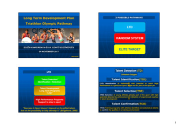
Chapter1OverviewThe Guardmaster safety relay (GSR) family is a group of advanced generalpurpose and special-purpose safety relays. This user manual addresses the CI,DI, DIS, EM, EMD, and SI safety relays from this family of relays.Hardware FeaturesFigure 1 - Safety RelaysRemovable Terminal BlocksStatus IndicatorsMulti-position Switches toset functionalityOptical Communication BusRemovable Terminal BlocksEach relay module is only 22.5 mm (0.9 in.) wide with four removable terminalblocks (two on top and two on bottom). The terminal blocks are keyed toconfirm that they are installed in their proper slots.Status IndicatorsMultiple status indicators provide status and diagnostics. Under faultconditions, the PWR/Fault status indicator blinks in specific patterns to helpdiagnose the fault.Rockwell Automation Publication 440R-UM013D-EN-P - December 20169
Chapter 1OverviewMulti-position SwitchesMost safety relays are configured by adjusting multi-position switches to settheir functionality (1). The switches are on the front face of the relay so you cansee the set position during, and after, configuration. During the configurationprocess, status indicators on the front face of the relay confirm the switchsettings.Optical Communication BusThe DI, DIS, EM, EMD, and SI safety relays have an optical communicationsbus that delivers status and diagnostics to the catalog number 440R-ENETREtherNet/IP module (not shown in Figure 1) without additional wiring. Foradditional information, see Ethernet Communication on page 55.Safety relays use single wire safety (SWS) signals that allow multiple safetyrelays to work in coordination with one another in small to medium size safetysystems. The SWS feature allows safety relays to communicate the highestsafety-rated control signal from one safety system to another over one wire(plus a common ground connection). The wire must be less than 30 m (98.4 ft)long.CI Safety Relay(Cat. No. 440R-S13R2)The CI safety relay has one dual-channel input with three electromechanicalrelay outputs. The CI safety relay can be configured for automatic ormonitored manual reset by adjusting the switch on the front. The CI safetyrelay has an SWS output, but does not support SWS input.The CI safety relay is compatible to the MSR127 safety monitoring relay. TheCI safety relay has the same number of inputs and outputs, the same width, andthe same terminal locations as the MSR127 relay.DI Safety Relay(Cat. No. 440R-D22R2)The DI safety relay has two dual-channel inputs and two electromechanicalrelay outputs. In addition, the DI safety relay has an SWS input and output.The DI safety relay can be set for automatic or monitored manual reset byadjusting the switch on the front panel. The configuration switch also sets theAND/OR logic that is applied to the inputs.DIS Safety Relay(Cat. No. 440R-D22S2)The DIS safety relay has two dual-channel inputs and four solid-state outputs.Two of the four solid-state outputs are designed to operate with highcapacitance loads. In addition, the DIS safety relay has an SWS input andoutput. The DIS safety relay can be set for automatic or monitored manualreset by adjusting the switch on the front panel. The configuration switch alsosets the AND/OR logic that is applied to the inputs.(1) The EM safety relay does not require configuration.10Rockwell Automation Publication 440R-UM013D-EN-P - December 2016
OverviewChapter 1EM Safety Relay(Cat. No. 440R-EM4R2)The EM safety relay is an expansion module with four immediately operatedelectromechanical relay outputs. The only input to the EM safety relay is anSWS input. The EM safety relay is designed to expand the outputs of the GSRfamily of host relays. The EM safety relay also has an SWS output for furtherexpansion.EMD Safety Relay(Cat. No. 440R-EM4R2D)The EMD safety relay is an expansion module with delayed electromechanicalrelay outputs. The EMD safety relay can be configured for one of the followingfunctions: On delay Off delay JogThe settings of the two switches on the front face of the relay configure thefunctionality and duration of the delay and jog.The main input to the EMD safety relay is the single wire safety input. Withthe SWS signal, the EMD safety relay is designed to expand the outputs of theGSR family of host relays. The EMD safety relay also has an SWS output forfurther expansion.An additional input is used with the jog function or to set the off delay asretriggerable. See EMD Safety Relay Timing Functions on page 41 for detaileddescriptions on the EMD safety relay timing functions.SI Safety Relay(Cat. No. 440R-S12R2)The SI safety relay has one dual-channel input with two electromechanicalrelay outputs. The SI safety relay can be configured for automatic or monitoredmanual reset by adjusting the switch on the front. The SI safety relay also hasan SWS output.The SI safety relay is similar in functionality to the MSR126 safety monitoringrelay.Rockwell Automation Publication 440R-UM013D-EN-P - December 201611
Chapter 1OverviewNotes:12Rockwell Automation Publication 440R-UM013D-EN-P - December 2016
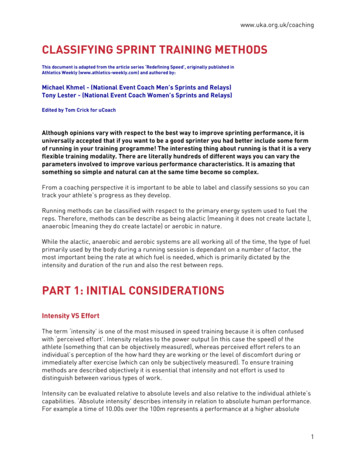
Chapter2InstallationAll safety relays in this manual have the same dimensions (Figure 2).Mounting DimensionsFigure 2 - Dimensions [mm (in.)]22.5(0.88)113.6 (4.47)119.14(4.69)DIN Rail Mounting andRemovalSafety relays mount onto 35 mm DIN rails: 35x7.5x1 mm (EN 50022-35x7.5).1. Hold the top at an angle (Figure 3).2. Slide down until the housing catches the rail.3. Swing the bottom down and push until the latch clips onto the rail.Figure 3 - DIN Rail MountingDIN Rail LatchDINRailRemovalTo remove a safety relay, use a screwdriver to pry the DIN rail latch downwardsuntil it is in the unlatched position. Then, swing the module up.Rockwell Automation Publication 440R-UM013D-EN-P - December 201613
Chapter 2InstallationSpacingSafety relays can be mounted directly next to other safety relays. When theEtherNet/IP module is used, the safety relay must be mounted within 10 mm(0.4 in.) of its neighboring module to maintain effective communication.Maintain a space of 50.8 mm (2 in.) above, below, and in front of the relay foradequate ventilation.Removable TerminalsSafety relays have removable terminals to ease wiring and replacement.Figure 4 - Removable Terminals121. Insert the tip of a small screwdriver into the slot near the terminalscrews.2. To unlock the terminal block, rotate the screwdriver.The terminal block can then be removed from the housing.Enclosure ConsiderationsMost applications require installation in an industrial enclosure to reduce theeffects of electrical interference and environmental exposure. PollutionDegree 2 is an environment where normally only non-conductive pollutionoccurs except that occasionally temporary conductivity that is caused bycondensation shall be expected. Overvoltage Category II is the load levelsection of the electrical distribution system. At this level, transient voltages arecontrolled and do not exceed the impulse voltage capability of the productinsulation.This equipment is intended for use in a Pollution Degree 2 industrialenvironment, in overvoltage Category II applications (as defined in IEC60664-1), at altitudes up to 2000 m (6562 ft) without derating. Thisequipment is considered Group 1, Class A industrial equipment according toIEC/CISPR 11. Without appropriate precautions, there may be difficultieswith electromagnetic compatibility in residential and other environments dueto conducted and radiated disturbances.14Rockwell Automation Publication 440R-UM013D-EN-P - December 2016
InstallationChapter 2This equipment is supplied as open-type equipment. It must be mountedwithin an enclosure that is suitably designed for those specific environmentalconditions that are present and appropriately designed to help prevent personalinjury as a result of accessibility to live parts. The enclosure must have suitableflame-retardant properties to help prevent or minimize the spread of flame, incompliance with a flame spread rating of 5VA, V2, V1, V0 (or equivalent) ifnon-metallic. The interior of the enclosure must be accessible only by the use ofa tool. Subsequent sections of this publication contain additional informationregarding specific enclosure-type ratings that are required to comply withcertain product safety certifications.For more information, see: Industrial Automation Wiring and Grounding Guidelines,Rockwell Automation publication 1770-4.1, for additionalinstallation requirements. NEMA Standard 250 and IEC 60529, as applicable, for explanations ofthe degrees of protection provided by different types of enclosure.Prevent Excessive HeatFor most applications, normal convective cooling keeps the relay within thespecified operating range. Verify that the specified temperature range ismaintained. Proper spacing of components within an enclosure is usuallysufficient for heat dissipation.In some applications, other equipment inside or outside the enclosure canproduce a substantial amount of heat. In this case, place blower fans inside theenclosure to help with air circulation and to reduce “hot spots” near thecontroller.Additional cooling provisions are necessary when high ambient temperaturesare encountered. Do not bring in unfiltered outside air. Place the controller inan enclosure to help protect it from a corrosive atmosphere. Harmfulcontaminants or dirt could cause improper operation or damage tocomponents. In extreme cases, you may need to use air conditioning to helpprotect against heat buildup within the enclosure.Rockwell Automation Publication 440R-UM013D-EN-P - December 201615
Chapter 2InstallationNotes:16Rockwell Automation Publication 440R-UM013D-EN-P - December 2016
Chapter3Power, Ground, and WireWiring Requirements andRecommendationATTENTION: Before you install and wire any device, disconnect power to thesystem.ATTENTION: Calculate the maximum possible current in each power andcommon wire. Observe all electrical codes that dictate the maximum currentallowable for each wire size. Current above the maximum rating causeswiring to overheat, which can cause damage. Allow for at least 50 mm (2 in.) between I/O wire ducts or terminalstrips and the relay. Route incoming power to the relay by a path separate from the devicewiring. Where paths must cross, their intersection must beperpendicular. Do not run signal or communications wiring and power wiring in thesame conduit. Route wires with different signal characteristics byseparate paths. Separate wiring by signal type. Bundle wiring with similar electricalcharacteristics together. Separate input wiring from output wiring. Label wiring to all devices in the system. Use tape, shrink-tubing, orother more dependable means to label wire. Use colored insulation aswell to identify wiring by signal characteristics. For example, use blue forDC wiring and red for AC wiring.Wire SizeEach terminal can accommodate copper wire with size from 0.2 2.5 mm2(24 14 AWG). Use copper that withstands 60 75 C (140 167 F).Terminal TorqueTorque terminals to 0.4 N·m (4 lb·in).Rockwell Automation Publication 440R-UM013D-EN-P - December 201617
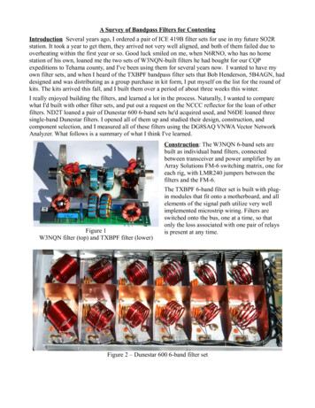
Chapter 3Power, Ground, and WireTerminal AssignmentsSafety relays have four terminals: two on the top and two on the bottom. Asshown in Figure 5, the X2 and X4 terminal markings apply to the rearterminals. The X1 and X3 terminals apply to the front terminals.Figure 5 - Terminal IdentificationX2X1S12 S22 AP S54A1 A2 P12 P22X1X2X3X4PWR/FaultIN151/L61Logic INX14/X24 L11X3X4L12 L11 Y32 S44X14 X24 51 L61Figure 6 shows the front face markings of each of the safety relays, includingthe terminal and status indicator identifications.Figur
Guardmaster Safety Relays Catalog Numbers 440R-S13R2, 440R-S12R2, 440R-D22R2, 440R-D22S2,