Transcription
[BLD122332]Robot Structural Analysis – From design tocalculationSafet IskaLearning Objectives Gain a better understanding of how Robot Structural Analysis Professional can beused and all its benefitsLearn how Robot Structural Analysis Professional is integrated to the users primarymodeling tool RevitLearn how to plan a model and understand what to think of before exporting toRobot Structural Analysis Professional, and what outcomes can be expected with abad modelGet an overview of the steel design and reinforcement design tool in RobotStructural Analysis ProfessionalDescriptionUsually our ultimate wish in a project is to eliminate the phase where the user has to remodelthe structure in our FEM-software to execute the load take down calculation, this is quite timeconsuming. The link between Revit and RSA is getting used more and more with the time butoften our first projects doesn’t appear to be that time saving because of the lack of knowledgeusers usually have in the first test. Learn what type of issues might appear, how to eliminate itand which benefits you as a user can have by using these software’s correctly.Robot Structural Analysis Professional (RSA) is a well-used Structural calculation software oreven sometimes called FEM-software provided by Autodesk. RSA offers advanced calculationmethods for different type of structural material such as concrete, steel and timber. It also allowsus to design our structure considering e.g. Eurocode, ASCE etc.Page 1
Speaker(s)Safet Iska, a proud Civil engineer & pioneer who is striving to solve customer questions andhelp them improve the way of working mainly within Autodesk s BIM-products. A technicalsales manager acting within the AEC area in the Nordic market at Symetri AB. Safet Iska isspecialized in FEM-software’s primary working with Autodesk solution Robot Structural analysis.Influencing the customer to adapt a new perspective of the word FEM and a more connectedBIM-workflow with Revit and Advance Steel.Email: safet.iska@symetri.comPage 2
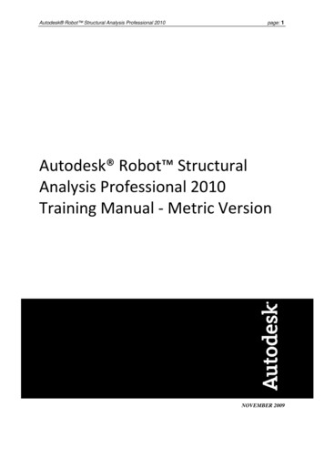
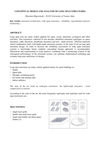
Graphical overview of the design process submitted with RSA and RevitIt is critical for a user to understand which process could be used when we are striving to usethe integration between Autodesk softwares, in this case particular Revit – Robot.Which barriers do we tear down with this integration?For a Structural engineer, it is of importance to eliminate specific obstacles when working in aproject. For instance, to specify information twice, remodel the structure for a certain analyzeand submit changes after they are made which is occurs quite often in projects.Below you can find a work-process which could be implemented after understanding thisprocess and which time-consuming moments can be eliminated by using Autodesk entationFabricationPage 3
1. KeywordsAnalytical line – Each structural object in Revit will provide us with a analytical line. A lineplaced in the center of the 3D geometry. This is the data that our FEM-software focus on.Two-way communication – Possibility to transfer specific data from one environment toanother and later update it back with different data to the same source.Load take-down calculation – Calculation of the forces acting from the top of the structure tothe ground.Claddings – A object which acts as a surface and doesn’t contain any weight, its purpose is toprovide us with more accurate load transfer.Maps – Solution to present static results by color, forces such as moment, shear and normalforces.Optimization – Enhance the objects performance so the loads applied on it is not causing toogreat strain and overcome the bearing capacity of the object.Page 4
2. The link between Robot Structural analysis and RevitWe will start by visualizing the export/update button for starter in both Revit and RSA.RSATake these following steps: Add-Ins Integration Autodesk Revit StructureRevitSimilar steps will be needed in Revit as well: Analyze Robot Structural Analysis link Once we have done the transfer from Revit to Robot the model will be completely dependent on how wellwe have prepared the analytical model. It is very important to have the lines connected so we can get anaccurate load transfer from one object to another, that’s how we can finalize the total behavior of thestructures deformation, critical points etc.Page 5
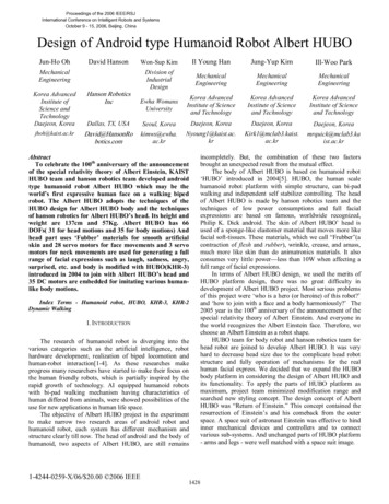
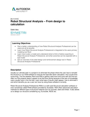
3. Preparing the model in RevitRevit will also assist us in the analytical part by defining constraints for the analytical lines. If we forinstance have applied an offset in the analytical model settings, Revit will automatically connect 2nodes if they are located within the defined distance.Additional function which have great impact on this workflow is Steel design from a third-partyproduct called Naviate Structure. Previous experience has revealed that when we have severalengineers working towards a central file in the same project there might appear accidentalchange. Should we move one object and others will follow, the exact height on similar objects isalso something which benefits us in the calculation phase.This solution helped us secure that there weren’t any accidental changes on the steel frames.By analyzing our current status of steel frames/objects we could easily follow if that model stillwas identical later on in the modelling phase.Page 6
A project sample of Steel design function is described below.Page 7
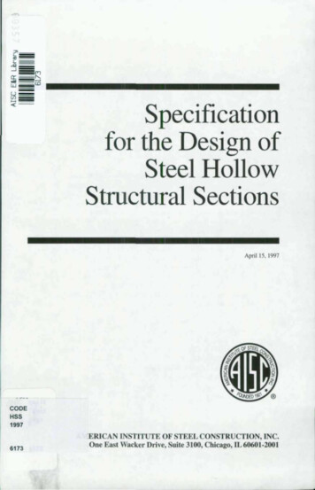
4. Design-phase in Robot Structural AnalysisWhen we finally have completed our Revit model and done a quick check that no surprisingchanges appear then we can export our model to Robot. Take to account that when the exportis finalized it might be a good step to check so all our profiles do have the right physical data.Such as profile geometry, steel quality and releases so we can adjust missing part and receivea good calculation performance.Easy step to filter this data can be done with bar selection tool as in the following picture below.When we later have completed the model check we can start the calculation part of the static forces. I willhighly recommend that we start by doing a quick calculation with just a dead load to assure that we do notget warnings that will be critical for the results. If that step is ok then we can proceed with the correctload-cases and combination.To include combinations and a lot of load-cases in the calculation will lead to a longer calculation timewhich will be very time consuming if we bump into some problems we must correct.In this particular case, we used claddings on rooftops instead of doing a manual calculation of the linearloads on each beam. With claddings, we can easily apply surface loads on it and robot will automaticallycalculate the linear load for us in each beam. We can also define how the load-transfer should behave,which objects should take up load and which shouldn’t.Page 8
The next step will allow us to examine the results such as moments, normal-/shearforces and reactionforces which will define the loads the piles will carry.Page 9
5. Concrete design – ReinforcementConcrete objects were further detailed in Robot, as our customer wished for fabric area reinforcement onthe slabs we took that into consideration when we executed the calculation for reinforcement.With Slab required reinforcement we could see which requirements was needed to fulfill the demands,this is presented by maps.After we received the required reinforcement we could easily go further to Provided Reinforcement anddefine which fabric area we wished for and apply it to the plate.The configurations for the slab will be defined in Calculation options and Reinforcement pattern.Page 10
After performing these steps, we now could get an estimated value of how many Fabric reinforcement net(K257) we needed to get an accepted solution. The reinforcement was manually placed in the Revit.For the foundation beams we used similar method as with the frames where we change the slabs tocladdings and could receive the linear loads which is distributed to the beams. In that way, we couldperform a reinforcement calculation, unfortunately this part was done manually after we received the rightlinear loads.Page 11
6. Steel design - OptimizationThe optimization phase of the steel objects was managed under steel design. First step is to apply rightparametric behavior of each system, such as columns, beams and trusses. If the calculation shall beaccurate we must apply defined member type on the objects.To be able to have more control of the objects we decided to divide the objects into groups for theoptimization. We had specific groups for columns, one for trusses and another one for the beams. Theoptimization is a process which is performed in several iterations to finalize a complete utilization of theobjects.Page 12
After creating our groups, we could then define how Robot should optimize the objects, by a type ofsection, weight etc.At last we could finally press calculations button to get an overview of the verification.All the objects that had an utilization of more than 100 % were increased in section and those with lowutilization was decreased, because of esthetic part was a thing we wanted to maintain we instead usedthe same type section for the certain frame, we didn’t want to have different size of the section on thesame frame.Page 13
7. Back to Revit from RobotIn this case because of the large number of objects and changes with sections and movements wedecided to perform this step in several updates so we don’t get too big changes on the model which willbe too hard to control.Observe when we update back the objects which has been exported to Robot from the start it is veryimportant that we do it by opening Revit and select which objects should be updated and then update.If we press send model from Robot to Revit then we will force the new Robot model into the opened Revitfile and there will appear two models. This step is something we only use when we have added newobjects in Robot which doesn’t include in the Revit model.Export steps when we have added objects in Robot that needs to be transferred to Revit.Page 14
8. ConclusionBy implementing this integrated workflow between Revit and Robot Structural analysis Autodesk ssolution offers the engineers a complete and unique opportunity. The workflow allows us to eliminateseveral time-consuming and unnecessary phases between the modelling and calculation span. Stepswe can eliminate which can be confirmed after this project scenario is following (see below). Remodel the structure. To manually calculate distribution of loads to each frame. Generate a lot of manual combinations and find out which one is the right combination for thespecific case. After optimization submit changes back to the modelling tool.It happens that the engineers often must manually calculate the load take down for the structure. Thishappens to be done by using simple 2D drawings as reference where we must measure distancesbetween the bearing objects. If the project is a multi-story building then this must be done for eachfloor and it takes more time then we really need to put down. A great benefit with 3D FEM-software’s isthat the engineers get a full overview of the structures behavior and in early steps finds out theweaknesses of the structure. Now that the 3D model can be exported to a FEM environment, thatgives us a great leap forward and leaves the engineer to dump the 2D drawings and plan views fromthe designer and can directly focus on the loads calculation uctural-analysis-professional.pdfGet going with Robot Structural analysis – Symetri ABVideohttps://www.youtube.com/watch?v bhEaucg3EBshttps://www.youtube.com/watch?v ksLjZd62DoY&index 10&list PLYggSrSwbZqow 60fiqJwS69mg1nQMzkPage 15
Robot Structural Analysis Professional (RSA) is a well-used Structural calculation software or even sometimes called FEM-software provided by Autodesk. RSA offers advanced calculation methods for different type of structural material such as concrete, steel and timber. It also allows us to design