Transcription
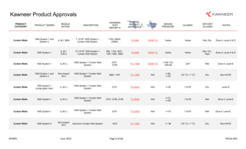
Application TechniqueSafety Function: Light Curtain and Configurable Safety RelayProducts: Guardmaster 440C-CR30 Configurable Safety Relay, 440L GuardShield Light Curtain, 100S-C Safety Contactors,800F E-Stop Button, 800F Reset ButtonSafety Rating: CAT. 4, PLe to ISO 13849-1: 2008TopicPageImportant User Information2General Safety Information3Introduction4Safety Function Realization: Risk Assessment4Light Curtain and Configurable Safety Relay Safety Function4Safety Function Requirements5Functional Safety Description5Bill of Material6Setup and Wiring6Configuration12Calculation of the Performance Level26Verification and Validation Plan29Verification of the Configuration35Additional Resources38
Safety Function: Light Curtain and Configurable Safety RelayImportant User InformationRead this document and the documents listed in the additional resources section about installation, configuration, andoperation of this equipment before you install, configure, operate, or maintain this product. Users are required tofamiliarize themselves with installation and wiring instructions in addition to requirements of all applicable codes, laws,and standards.Activities including installation, adjustments, putting into service, use, assembly, disassembly, and maintenance are requiredto be carried out by suitably trained personnel in accordance with applicable code of practice.If this equipment is used in a manner not specified by the manufacturer, the protection provided by the equipment may beimpaired.In no event will Rockwell Automation, Inc. be responsible or liable for indirect or consequential damages resulting from theuse or application of this equipment.The examples and diagrams in this manual are included solely for illustrative purposes. Because of the many variables andrequirements associated with any particular installation, Rockwell Automation, Inc. cannot assume responsibility orliability for actual use based on the examples and diagrams.No patent liability is assumed by Rockwell Automation, Inc. with respect to use of information, circuits, equipment, orsoftware described in this manual.Reproduction of the contents of this manual, in whole or in part, without written permission of Rockwell Automation,Inc., is prohibited.Throughout this manual, when necessary, we use notes to make you aware of safety considerations.WARNING: Identifies information about practices or circumstances that can cause an explosion in a hazardous environment,which may lead to personal injury or death, property damage, or economic loss.ATTENTION: Identifies information about practices or circumstances that can lead to personal injury or death, propertydamage, or economic loss. Attentions help you identify a hazard, avoid a hazard, and recognize the consequence.IMPORTANTIdentifies information that is critical for successful application and understanding of the product.Labels may also be on or inside the equipment to provide specific precautions.SHOCK HAZARD: Labels may be on or inside the equipment, for example, a drive or motor, to alert people that dangerousvoltage may be present.BURN HAZARD: Labels may be on or inside the equipment, for example, a drive or motor, to alert people that surfaces mayreach dangerous temperatures.ARC FLASH HAZARD: Labels may be on or inside the equipment, for example, a motor control center, to alert people topotential Arc Flash. Arc Flash will cause severe injury or death. Wear proper Personal Protective Equipment (PPE). Follow ALLRegulatory requirements for safe work practices and for Personal Protective Equipment (PPE).2Rockwell Automation Publication SAFETY-AT138C-EN-P - February 2016
Safety Function: Light Curtain and Configurable Safety RelayGeneral Safety InformationIMPORTANTThis application example is for advanced users and assumes that you are trained and experienced in safety system requirements.Risk AssessmentsATTENTION: Perform a risk assessment to make sure that all task and hazard combinations have been identified and addressed.The risk assessment can require additional circuitry to reduce the risk to a tolerable level. Safety circuits must consider safetydistance calculations, which are not part of the scope of this document.Contact Rockwell Automation to learn more about our safety-risk assessment services.Safety Distance CalculationsATTENTION: Compliant safety circuits must often consider a safety distance or access time calculation.Non-separating safeguards provide no physical barrier to prevent access to a hazard. Publications that offer guidance forcalculating compliant safety distances for safety systems that use non-separating safeguards, such as light curtains, scanners,two-hand controls, or safety mats, include the following:EN ISO 13855:2010 (Safety of Machinery – Positioning of safeguards with respect to the approach speeds of partsof the human body)ANSI B11:19 2010 (Machines – Performance Criteria for Safeguarding)Separating safeguards monitor a moveable, physical barrier that guards access to a hazard. Publications that offer guidancefor calculating compliant access times for safety systems that use separating safeguards, such as gates with limit switches orinterlocks (including SensaGuard switches), include the following:EN ISO 14119:2013 (Safety of Machinery – Interlocking devices associated with guards - Principles for design andselection)EN ISO 13855:2010 (Safety of Machinery – Positioning of safeguards with respect to the approach speeds of partsof the human body)ANSI B11:19 2010 (Machines – Performance Criteria for Safeguarding)In addition, consult relevant national or local safety standards to assure compliance.Rockwell Automation Publication SAFETY-AT138C-EN-P - February 20163
Safety Function: Light Curtain and Configurable Safety RelayIntroductionLight curtains are used to detect attempted access to a hazardous area. In normal operation, if a light curtain detects anobject, such as the operator's hand, it causes the safety system to stop any hazardous motion in the hazardous area.This safety function application technique explains how to wire and configure a Point of Operation Control (POC)GuardShield light curtain and an E-Stop function. The system is based on a Guardmaster 440C-CR30 softwareconfigurable safety relay.Safety Function Realization: Risk AssessmentThe required performance level is the result of a risk assessment and refers to the amount of the risk reduction to be carriedout by the safety-related parts of the control system. Part of the risk reduction process is to determine the safety functions ofthe machine. In this application, the performance level required (PLr) by the risk assessment is Category 3, PerformanceLevel d (CAT. 3, PLd), for each safety function. A safety system that achieves CAT. 3, PLd, or higher, can be consideredcontrol reliable. Each safety product has its own rating and can be combined to create a safety function that meets orexceeds the PLr.From: Risk Assessment (ISO 12100)1. Identification of safety functions2. Specification of characteristics of each function3. Determination of required PL (PLr) for each safety functionTo: Realization and PL EvaluationLight Curtain and Configurable Safety Relay Safety FunctionThis application technique includes two safety functions: Safety-related stop of hazardous motion, initiated by a light curtain. Emergency stop of hazardous motion, initiated by an E-Stop button.4Rockwell Automation Publication SAFETY-AT138C-EN-P - February 2016
Safety Function: Light Curtain and Configurable Safety RelaySafety Function RequirementsInterrupting the light curtain or pressing the Emergency Stop button stops and prevents hazardous motion by removal ofpower to the motor. The motor then coasts to a stop (Stop Category 0). When the safety system is reset, hazardous motionand power to the motor do not resume until a secondary action occurs (for example, pressing the start button). Faults at thelight curtain, wiring terminals, or safety controller are detected before the next safety demand. The safe distance from thelocation of the light curtain to the hazard must be established such that the hazardous motion stops before you can reachthe hazard. The safety function in this example is capable of connecting and interrupting power to motors rated up to 9 A,600V AC.Position the reset button outside of the hazardous area where it is possible to view the entire hazardous area.ATTENTION: If it is not possible to view the entire hazardous area, additional safety-rated presence-sensing devices must be usedto detect persons in that area, for example, by using a laser scanner or safety mat inside the cell.The safety functions in this application technique each meet or exceed the requirements for Category 3, PerformanceLevel d (CAT. 3, PLd), per ISO 13849-1 and control reliable operation per ANSI B11.19.Functional Safety DescriptionHazardous motion is stopped or prevented by interrupting the field of view of the light curtain. The 440L light curtain isconnected to the 440C-CR30 configurable safety relay. The safety outputs of the 440C-CR30 relay control the power tothe 100S-C contactor coils. Whenever the 440C-CR30 relay de-energizes the safety contactors, the hazardous motioncoasts to a stop (Stop Category 0). The safety relay monitors the status of the 100S-C output contactors via mechanicallylinked auxiliary contacts and does not reset unless both sets of main motor contacts are open. After the load clears the lightcurtain, all safety input signals are correct, no faults are detected, and the reset push button is pressed (for 0.25 to 3.0seconds) and released, the 440C-CR30 relay turns its safety outputs ON, providing power to the contactor coils. The EStop is connected to the 440C-CR30 relay, which uses pulse checking to monitor the E-Stop for actuation and faults.Whenever the E-Stop is actuated (pressed), the 440C-CR30 relay turns OFF its safety outputs, and the hazardous motionis stopped. After the E-Stop button is released, all safety input signals are correct, no faults are detected, and the reset pushbutton is pressed (for 0.25 to 3.0 seconds) and released, the 440C-CR30 relay turns its safety outputs ON, providing powerto the contactor coils.Rockwell Automation Publication SAFETY-AT138C-EN-P - February 20165
Safety Function: Light Curtain and Configurable Safety RelayBill of MaterialThis application uses these products.Cat. No.DescriptionQuantity440C-CR30-22BBBGuardmaster 440C-CR30 software-configured safety relay, PLe SIL 3, 22 safety I/O, embedded serial port, USBprogramming port, 2 plug-in slots, 24V DC12080-IQ4OB44-channel digital input/output combination module1440L-P4JL0640YDGuardShield safety light curtain, resolution 14 mm (.55 in.), protective height 640 mm (25.2 in.), 64 beams, integratedlaser alignment1889D-F4AC-5DC Micro (M12), female, straight, 4-pin, PVC cable, yellow, unshielded, 22 AWG, 5 meter (16.4 feet)1889D-F8AB-5DC Micro (M12), female, straight, 8-Pin, PVC cable, black, unshielded, 24 AWG, 5 meter (16.4 feet)1800FP-MT44PX02S800F non-Illuminated mushroom operators, twist to release, 40 mm (1.6 in.), round plastic (type 4/4X/13, IP66), red,plastic latch mount, 0 N.O. contacts, 2 N.C. contacts, self-monitoring, standard pack1800FP-F611PX10800F push button - plastic, flush, blue, R, plastic latch mount, 1 N.O. contacts, 0 N.C. contacts, standard, standard pack1100S-C09EJ23CMCS 100S-C safety contactor, 9 A, 24V DC (with electronic coil)2Setup and WiringFor detailed information on installing and wiring, refer to the publications listed in the Additional Resources on the backcover.System OverviewWhen an object, such as the operator's hand, interrupts the light curtain, the light curtain turns its two OSSD outputsOFF. These signals are connected to the safety input terminals of the 440C-CR30 safety relay. When the light curtain'sOSSD outputs turn OFF, the safety relay responds by turning OFF its own redundant safety outputs. This action removesthe 24V signal from the coils of the two safety contactors whose main motor contacts then open, thus removing powerfrom the motor. This action causes the motor to coast to a stop (Stop Category 0). Stopped is the safe state.The 100S-C safety contactors are the final control devices. A 24V signal is passed through mechanically-linked, normallyclosed (N.C.) auxiliary contacts of the 100S-C contactors to inputs on the 440C-CR30 safety relay, enabling the relay tomonitor the status of the main contacts. This 24V feedback (monitoring) signal is only present at the safety relay's inputs ifthe main contacts are open, meaning that the contactors are in a safe state. If one of the main motor contacts is welded shut,the auxiliary N.C. contacts are held open by the mechanical linkage and the 24V feedback signal does not reach the inputsof the safety relay. The safety relay does NOT reset under this condition. The failed contactor would have to be replaced.Once the light curtain is restored, its OSSD outputs turn ON. When the safety relay detects these signals and the feedbackmonitoring signal, when no faults are detected, and the reset push button is pressed (for 0.25 to 3.0 seconds) and released,the 440C-CR30 relay turns its safety outputs ON, providing power to the contactor coils. Position the reset button whereit is possible for the operator to view the entire hazardous area. If a person is in the hazardous area, the reset button shouldnot be pressed. If it is not possible to view the entire accessible hazardous area when operating the reset button, usesupplemental safeguarding, such as a safety mat or a laser scanner to monitor the hazardous area. Another option is to usemechanical implementations that make it impossible to be in the hazardous area without interrupting the light curtain.6Rockwell Automation Publication SAFETY-AT138C-EN-P - February 2016
Safety Function: Light Curtain and Configurable Safety RelayThe reset button and contactor feedback-monitoring circuits connect to the 2080 plug-in I/O module. This module is notsafety rated. It is acceptable to use standard inputs for the reset and feedback because they are not safety-rated signals. Theyare simple 24V signals. The 440C-CR30 safety relay limits the use of standard I/O to functionality that does not requiresafety rated signals. By comparison, the E-Stop and light curtain signals must not be connected to the standard I/O plug-inmodule. These signals must be connected to safety-rated inputs. Both the configuration software and the firmware preventyou from using standard inputs for signals that must be safety rated. Reset and feedback monitoring signals can beconnected to safety rated inputs if so desired. This example uses the 2080 plug-in I/O module to show the capability of the440C-CR30 safety relay.The light curtain monitors its internal circuitry and its OSSD outputs for faults. When the light curtain detects a fault inthe internal circuitry, the light curtain responds by turning its OSSD outputs OFF. A fault on the OSSD outputs isdetected either immediately, or upon the next safety demand. The light curtain turns its OSSD outputs OFF when itdetects an output fault, such as a short-circuit to another signal, or between the two OSSD channels. Most internal andwiring faults of the light curtain require you to cycle power after removing the cause of the fault to internally clear the faultand enable the light curtain to turn its outputs ON.The 440C-CR30 safety relay sends test pulse signals from multi-purpose terminals 12 and 13 through the contacts of theE-Stop, which are connected back to the safety inputs on the safety relay. Pressing the E-Stop interrupts this circuit. Thesafety relay responds by turning its safety outputs OFF, which de-energize the coils of the 100S-C contactors. This causesthe main motor contacts to open, removing power from the motor and causing it to coast to a stop (Stop Category 0).The 440C-CR30 safety relay monitors the E-Stop circuit for faults. Loose wires, shorts to 24V, shorts to ground, contactsfailed closed, and cross faults are detected. When a fault is detected, the safety relay responds by turning its safety outputsOFF, taking the system to a safe state.The 440C-CR30 safety relay checks itself for internal faults and turns its outputs off, if any are detected.No single fault results in the safety system failing to perform its safety function. A single fault is detected before or upon thenext demand on the safety system. The system cannot be reset until the fault is corrected.When a light curtain is used, additional mechanical protective devices must be installed so that hazardous machineelements cannot be reached by personnel or material without first passing through the protective field of the light curtain.For example, the entire rest of the hazardous cell should be surrounded by expanded metal fencing of sufficient height and/or interlocked gates, including the area above and beneath the protective area of the light curtain, if it would otherwise bepossible for a person to access the hazard through these spaces. Refer to the relevant standards and the GuardShield Type 4and GuardShield Remote Teach User Manual, publication 440L-UM003, for additional information on how to positionthe light curtain.The selection of light curtain model, protective height, resolution, and other specifications is dependent on the results ofthe risk assessment for the specific application. Refer to the relevant standards and the GuardShield Type 4 andGuardShield Remote Teach User Manual, publication 440L-UM003, for additional information. These factors also affectthe safety distance calculation.The Guardmaster 440C-CR30 Configurable Safety Relay User Manual, publication 440C-UM001, provides usefulguidance regarding the calculation of the safety-system response time.IMPORTANTAn example calculation is shown in this document, but you must perform a final calculation for your specific application based onthe safety system specification, as well as the machine stopping time.Rockwell Automation Publication SAFETY-AT138C-EN-P - February 20167
Safety Function: Light Curtain and Configurable Safety RelaySafety Distance CalculationA safety light curtain provides no physical barrier between a person and the hazardous motion. The safety light curtainmust be installed at a sufficient distance from the hazardous motion to make sure that someone putting a hand through thelight curtain cannot reach the hazard before it has stopped. This distance is referred to as the Safety Distance. The SafetyDistance (S or Ds) required varies from installation to installation, and therefore must be calculated for each specificapplication. This application technique provides example calculations based on the formulae from both the internationalstandard ISO 13855 and the U.S. standard ANSI B11:19.The Safety Distance formula for vertically installed safety light curtains from ISO 13855:S (K x T) CS: the minimum distance, in millimeters (mm)K: a parameter, in millimeters per second (mm/s), derived from data on approach speeds of the body or parts of thebodyT: the overall stopping performance in second(s) based on the machine stopping time plus the safety system totalreaction timeC: the intrusion distance in millimeters (mm)For the purposes of this example, we use the following values:K 2000 mm per second (78.8 in/s); or, when S 500 mm (19.7 in.), K 1600 mm per second (63 in/s) (whenusing the latter, a minimum S of 500 mm (19.7 in.) must be used)T 410 ms [300 ms (machine stopping time) 20 ms (light curtain) 45 ms (440C-CR30 relay) 45 ms (K1 andK2 contactors)]IMPORTANT: The specific machine stopping time must be measured for each application.C 0 mm (0 in.) [8 x (d-14) but not less than 0 where d is the resolution of the light curtain (d 14 mm (.55 in.))]S (K x T) C 2000 mm/s (78.7 in/s) x 0.41 s 0 mm (0 in.) 820 mm. (32.3 in.)Since 820 mm (32.3 in.) 500 mm (19.7 in.), we repeat the calculation using K 1600 mm/s (63 in/s).S (K x T) C 1600 mm/s (63 in/s) x 0.41 s 0 mm (0 in.) 656 mm (25.8 in.)IMPORTANT: If the calculation of S results in a value less than 500 mm (19.7 in.) when using K 1600 mm/s(63 in/s), a safety distance of 500 mm (19.7 in.) must be used.The light curtain must not be mounted closer than 656 mm (approx. 26 in.) from the hazardous motion being guardedagainst.IMPORTANT8For Point of Operation Control Light Curtain applications, the machine stopping time is critical–the machine must be capable ofstopping in a very short period of time. In the example, we use a machine stopping time of 300 ms. The machine must stop within300 ms every time to be able to use this number. By comparison, if the stopping time was 500 ms, the safety distance would be976 mm (38.4 in.). The light curtain would need to be mounted 320 mm (12.6 in.) farther away from the hazard just because ittakes 0.2 seconds longer to stop. It is very important to understand the effect that stopping time has on the safety distance.Rockwell Automation Publication SAFETY-AT138C-EN-P - February 2016
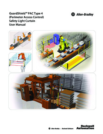
Safety Function: Light Curtain and Configurable Safety RelayThe Safety Distance formula from ANSI B11:19 is only slightly different and results in a very similar distance, as follows:Ds K x (Ts Tc Tr Tbm) Dpf.K: the ‘standard’ hand speed of 1600 mm per second (63 inches per second)Ts: the stop time of the machineTc: the response time of the safety systemTr: the response time of the presence sensing deviceTbm: additional time allowed for the brake monitor (if any) to compensate for variations in normal stopping timeDpf : the distance a ‘standard’ hand could possibly move through the light curtain before it is detected. This is a fixedvalue based on the light curtain resolution.For the purposes of this example, we use the following values:K 1600 mm per second (63 inches per second)Ts 300 ms (0.3 sec.) for the purposes of this application technique.IMPORTANT: The specific machine stopping time must be measured for each application.Tc 90 ms 45 ms (440C-CR30 relay) 45 ms (K1 and K2 contactors)Tr 20 ms (light curtain)Tr Tc 90 20 110 ms 0.11 secondTbm 0 (No brake is used in this application.)Dpf 1 in.Ds K x (Ts Tc Tr Tbm) Dpf 63 x (0.3 0.09 0.02 0) 1 63 x 0.41 1 680.7 mm (26.8 in.)The light curtain must not be mounted closer than 680.7 (26.8 in.) from the guarded hazard.Minimum Distance from Reflecting SurfacesThe infrared light from the sender may be reflected off of shiny surfaces and be received by the system’s receiver. If thiscondition occurs, it can result in an object not being detected when it enters the GuardShield sensing field.All reflecting surfaces and objects (for example, material bins) must therefore be located at a minimum distance (a) fromthe protective field of the system. The minimum distance a depends on the distance (D) between sender and receiver.aDistance D (meters)Follow these steps to determine the minimum distance from the reflecting surfaces.1. Determine the distance, (D) in meters, between the sender and receiver.Rockwell Automation Publication SAFETY-AT138C-EN-P - February 20169
Safety Function: Light Curtain and Configurable Safety Relay2. Read the minimum distance, (a) in millimeters, from the graph.a [mm]D [m]a minimum distance to reflecting surfacesD distance between transmitter and receiverThe effective aperture angle for the GuardShield system is 2.5 at a mounting distance of 3.0 m (9.8 ft). Calculate theminimum distance to reflecting surfaces depending on the distance between the transmitter and the receiver, using anaperture angle of 2.5 , or take the appropriate value from the following table.Distance between transmitterand receiver [m (ft)]MInimum distance to reflectingsurface [mm (in.)]0.2 3.0 (0.65 9.8)135 (5.31)4.0 (13.1)175 (6.88)5.0 (16.4)220 (8.66)6.0 (19.6)265 (10.43)7.0 (22.9)310 (12.2)10.0 (32.8)440 (17.32)16.0 (52.4)700 (27.55)10Rockwell Automation Publication SAFETY-AT138C-EN-P - February 2016
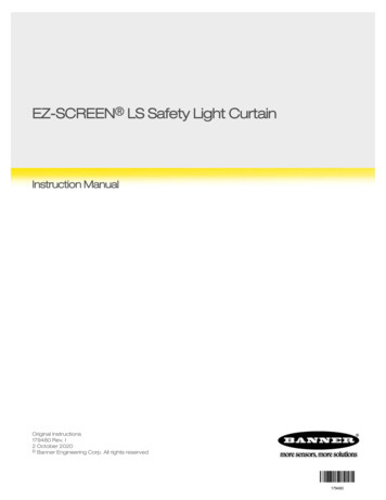
Safety Function: Light Curtain and Configurable Safety RelayElectrical Schematic24V DCDC- Class224V- C-CR30100S-CxxEJx* (2)EO 18A1K1A2MP 12EI 00EO 19A1K2A2EI 01MP BrnL1 L2 L3ReceiverReceiverPinkPnkGrayGryEI 02ExternalExternal SwitchedSwitchedStop/Start CircuitStop/StartCircuitEI I-00800Fx-F6xK1K2Plug-in I/OPlug-InI/OSlot 2Slot2I-01I-02A4A3B4B313849-2requires transientsuppressionacrossthe asloada asa BasicSafetyPrincipal.Principal. TheThe'EJ'“EJ”electroniccoil providessuppression.*ISO 13849-2 etyelectroniccoil suitableprovidessuitable suppression.Rockwell Automation Publication SAFETY-AT138C-EN-P - February 201611
Safety Function: Light Curtain and Configurable Safety RelayConfigurationConfigure the Input and Output DevicesThe light curtain uses the standard, default configuration. If the configuration DIP switches may have been changed, referto the GuardShield Type 4 and GuardShield Remote Teach User Manual, publication 440L-UM003, for instructions onresetting to the default parameters. The E-Stop and safety contactors are simple electromechanical devices that do notrequire configuration.Configure the 440C-CR30 RelayThe 440C-CR30 safety relay should be running firmware version 7.00 or later. A free firmware update is available for olderunits. The 440C-CR30 relay is configured by using the free Connected Components Workbench software, release 7.00 orlater. A detailed description of each step is beyond the scope of this document. Knowledge of the Connected ComponentsWorkbench software is assumed.Follow these steps to configure the Guardmaster 440C-CR30 relay by using Connected Components Workbenchsoftware.1. In Connected Components Workbench software, choose View and then Device Toolbox.2. In the Device Toolbox, expand the Catalog section and the Safety folder.3. Double-click the 440C-CR30 relay to add it to the project.12Rockwell Automation Publication SAFETY-AT138C-EN-P - February 2016
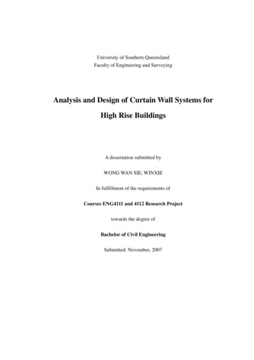
Safety Function: Light Curtain and Configurable Safety Relay4. In the Project Organizer, double-click the Guardmaster 440C-CR30 safety relay.5. To add the I/O module called for in this circuit, right-click the right-hand plug-in slot of the relay, and choose2080- IQ4OB4.TIPThe I/O module is shown in standard gray because it is not a safety I/O module. That is permissible in this application because it isnot used to connect safety-rated signals. Inputs such as Reset buttons and Feedback are not safety-rated signals. By using thestandard I/O plug-in module for these non-safety signals, you can reserve the limited number of safety inputs and outputs forsafety-rated signals.Rockwell Automation Publication SAFETY-AT138C-EN-P - February 201613
Safety Function: Light Curtain and Configurable Safety Relay6. Click Edit Logic to open the function block editor workspace.TIPIf you don't see the Toolbox, click View and choose Toolbox.Configure the InputsFollow these steps to configure the input safety monitoring functions.1. Click and drag an Emergency Stop Safety Monitoring function (SMF) from the Toolbox to the upper left-handSafety Monitoring target block in the logic editor.14Rockwell Automation Publication SAFETY-AT138C-EN-P - February 2016
Safety Function: Light Curtain and Configurable Safety RelayConnected Components Workbench software automatically assigns the next available terminals for both the inputsand the test sources. Any necessary configuration of those I/O points is also done automatically by the software. Inthis case, the default assignments are correct and no terminal changes are required for this application.2. In the Toolbox, click and drag Light Curtain to the target block below the E-Stop SMF 1.3. To add a Reset safety monitoring function, click and drag a Reset from the Toolbox to the target block below theLight Curtain SMF 2.4. On the Reset SMF 3, click the input terminal EI 04 and select Plug-in 2 Inputs P2 00.Rockwell Automation Publication SAFETY-AT138C-EN-P - February 201615
Safety Function: Light Curtain and Configurable Safety RelayNote that the reset can come from a standard plug-in input or even from the serial port, via a Modbus message.Configure the OutputsFollow these steps to configure the Safety Output Function (SOF).1. In the Toolbox under Safety Output Function Blocks, click and drag Immediate OFF to the first Safety Outputfunction target on the logic editor.Connected Components Workbench software automatically assigns the first two available safety output terminals ofthe 440C-CR30 relay, EO 18 and EO 19 (embedded safety outputs 18 and 19, respectively). These outputs drivethe two 100S-C safety contactors. The PT to the right of the terminal assignment stands for Pulse Testing, atechnique used to detect if the output terminal is short-circuited to 24V DC or another safety output terminal.Other output terminals have additional options for configuration besides Pulse Testing, but for terminals 18 and 19,it is the only possible configuration.16Rockwell Automation Publication SAFETY-AT138C-EN-P - February 2016
Safety Function: Light Curtain and Configurable Safety Relay2. From the Reset Input pull-down menu on the Safety Output Function (SOF), choose SMF3 to use the Reset we setup in the previous section.Configure the LogicIn this application, pressing the Emergency Stop disconnects power from the motor. An interruption of the light curtainalso disconnects power from the motor. Using an AND function configures the outputs of the 440C-CR30 relay to turnON, allowing the system to run when the E-Stop is closed, that is when the N.C. E-Stop button is released and clear, andthe light curtain is also clear.1. In the Toolbox, under the Logic Functions, click a
seconds) and released, the 440C-CR30 relay turns its safety outputs ON, providing power to the contactor coils. The E-Stop is connected to the 440C-CR30 relay, which uses pulse checking to monitor the E-Stop for actuation and faults. Whenever the E-Stop is actuated (pressed), the 440C-CR30 relay turns OFF its safety outputs, and the hazardous .