Transcription
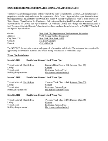
OWNER REQUIREMENTS FOR WATER MAINS AND APPURTENANCESThe following are the requirements of the owner of the water system for this Contract. All manufacturer orproprietary material designations are the requirement of the Owner. Approval of an equal item other thanthat specified must be granted by the Owner. For further NYCDEP requirements refer to NYC Bureau ofWater Supply "Specification for Furnishing, Delivering and Laying Steel Pipe and Appurtenances", and“Specifications for Ductile Iron Pipe with Push- On Joints and Ductile Iron Fittings with Mechanical Joints 6inch Through 48 inch in Diameter”, latest revision. Item numbers shown below refer to NYSDOT Standardand Special Specifications.Owner:Address:City, State, ZIP:Contact:Phone #:New York City Department of Environmental Protection96-05 Horace Harding ExpresswayNew York, New York 11373Mr. Luis Caminero(718)-595-4204The NYCDEP does require review and approval of materials and details. The estimated time required forapproval by the Owner of materials and details during construction is 40 business days.Water Pipe InstallationItem 663.0106Ductile Iron Cement Lined Water PipeType of Material: Ductile IronLining:Type of Joint:Bedding Requirements:Item 663.0108Ductile Iron Cement Lined Water PipeType of Material: Ductile IronLining:Type of Joint:Bedding Requirements:Item 663.0112Pressure/Thick Class or DR: Pressure Class 350CementRestrained Push on TypeFlat bottom undisturbed soilPressure/Thick Class or DR: Pressure Class 350CementRestrained Push on TypeFlat bottom undisturbed soilDuctile Iron Cement Lined Water PipeType of Material: Ductile IronLining:Type of Joint:Bedding Requirements:Pressure/Thick Class or DR: Pressure Class 350CementRestrained Push on TypeFlat bottom undisturbed soil
Bridge Mounted Water PipeItem 663.0512Bridge Mounted Water PipeUnder this item, the Contractor shall conform the requirements of the NYC Bureau of Water Supply"Specification for Furnishing, Delivering and Laying Steel Pipe and Appurtenances", latest revision.Water Main with Flanged and Welded JointsThe water main shall be sand blasted, primed and coated on the interior and exterior as per NYCDEP –BWSWC "Specification for Furnishing, Delivering and Laying Steel Pipe and Appurtenances", latestrevision.Flanges for flanged joints, where called for on the Contract Drawings, shall be standard forged steel hubslip-on flanges in accordance with AWWA C207-86 (or latest revision), Class E. Flanges shall be madefrom seamless forgings which meet the requirements of the Standard Specifications for Forgings, CarbonSteel for General-Purpose Piping, ASTM Designation A18l-87, Class 70 or the Standard Specification forForgings, Carbon Steel for Piping Components, ASTM Designation A105-87.Flanges shall be flat faced and shall be welded front and back with continuous fillet weld size equal to thepipe wall thickness. Flanges shall be spot faced or back faced at the rear; such facing shall not reduce themin. flange thickness by more than 1/16 in. Dimensions of flanges shall conform to Class E hub-type slipon flanges in accordance with ANSI/AWWA C207-86 except for insulated flanged joints. For insulatedflanged joints the bolt hole diameter shall be increased 1/16 in. for flanges of pipes 16 in. dia. or less and 1/8in. for flanges of pipes greater than 16 in. diameter. For flanges for outlet connections see NYCDEP,BWSWC Standard Drawing No. 68226-Y-A, latest revision; for flanges for insulated flanged joints see Std.Dwg. No. 46104-W, latest revision. Each flange joint shall be drilled and tapped for ¼ in. for subsequent airtesting as shown on St. Dwg. No. 35310-C-Y.Center gaskets shall be full faced rubber with cotton cloth insert or epoxy/glass, 1/8 in. thick, with bolt holesand bolt circle to match the AWWA Standard Class E type flanges. Material for gaskets shall be cottoncloth-reinforced SBR rubber, Style 159 with a min. 558 kV/in dielectric strength and a 50 KSI compressivestrength.Bolts, nuts and washers for un-insulated joints shall be carbon steel to meet the requirements of theStandard Specification for Carbon Steel Bolts and Studs, 60 KSI tensile strength, ASTM Designation A 307,Grade B for bolts and Grade A for nuts.Corporation StopCorporation stop is to be supplied by the NYSDEP and is to be picked up by the State’s Contractor at aDEP storage yard designated by the Engineer. The Contractor shall do all loading, hauling andunloading of the materials furnished by the NYCDEP.Insulating JointsConnection between steel and ductile iron pipes, between flange at the casing pipe and restrained flange atthe water main and between the water main pipe and expansion joint shall be made by insulated flange jointas shown on NYCDEP-BWSWC Standard Drawing 46104-W, latest revision.For insulated joints, bolts and washers shall be stainless steel Type 304 and meet the requirements of theStandard Specification for Alloy Steel Nuts and Bolts for High-Pressure and High Temperature Service,ASTM Design. A 193, Grade B 8A, Class A.
Nuts, for insulated joints, shall be Type 303 stainless steel and meet the requirements of the StandardSpecification for Carbon and Alloy Steel Nuts and Bolts for High-Pressure and High Temperature Service,ASTM Design. A-194-88, Grade 8FA.Sets of insulating sleeves and washers shall include the following items per bolt:a. One. full length mylar insulating sleeve, with a wall thickness of 1/32 in.,b. Two insulating washers, phenolic, 1/8 in. thick, with outside diameter 1/32 in. larger than that ofthe adjacent stainless-steel washers,c. Two stainless steel washers, annealed, Type 304, 1/8 in. thick.Welded JointsSteel pipes 30 in. diameter and larger shall be field welded using fillet welded field lap joint as shown on theNYCDEP-BWSWC Standard Drawing No. 353l0-C-Y, latest revision. Field welded lap joints shall be airtested as specified in the NYC DEP-BWSWC Standard Specification for "Furnishing, Delivering andLaying Steel. Pipes and Appurtenances", latest revision.Steel pipes with diameters less than 30 in. shall be field welded, where indicated on the plans usingStainless Steel Tips Class 304 L as shown on NYC DEP-BWSWC Standard Drawing No. 48407-Z,latest revision. Field weld shall be full penetration butt weld and shall be radiographed after completion tothe satisfaction of the Engineer. The electrodes for welding stainless steel to stainless steel (field weld)shall be of the type E308L stainless steel.Final TestingThe completed steel water main shall be tested. Testing shall be in strict accordance with therequirements of the N.Y.C.B.W.S. Standard Water Main Specifications, latest revision. Weldedpipe field joints shall be X-rayed to the satisfaction of the Engineer and the flanged pipe tested for strengthand leakage at a test pressure of 150 PSI for a minimum of 2 hours, unless the time period is extended by theEngineer.The Contractor shall repair all leakage discovered under the test and repeat the test at no extra cost to theState until no leakage can be observed.The Contractor shall furnish all apparatus, material and labor, with the exception of “City” water, necessaryfor making the tests.Expansion JointsExpansion joint shall be of the stainless-steel self-equalizing two-ply bellow type, with stainless steel limitrods, flanges and covers. Expansion joint shall be rated for internal operating water pressure of 150 PSI and300 PSI test pressure.The design value of axial movement due to expansion or contraction shall be 2 in. per 100 ft. of length ofpipe measured between fixed end points. Expansion joint and limit rods shall be delivered and installed inmid-way position.Expansion Joints are comprised of the following components:1. Flanges shall be stainless steel, complying with the requirements of ASTM A182, Type A316, flatfaced, 150 ANSI standard drilling for flanges 6 inches through 24 inches in diameter, andAWWA Standard Class E type for flanges 30 in. and larger in diameter. Bolt hole diameter shall beincreased to accommodate installation of Mylar Sleeve as specified on the NYCBWS StandardDwg.No.46104-W, latest revision.
2. Expansion joint body and external cover shall be stainless steel complying with ASTM A240, Type316. The body shall be 3/8 in. thick and the cover shall be 1/8 in. thick. The external cover shallprovide protection for the bellows during shipment, installation and operation.3. Two-Ply Bellows shall meet the requirements of the American Welding Society Standard DesignationASTM A240, Type 316 stainless steel and shall be 1/16 in. in thickness. The bellows shall behydraulically formed, using internal pressure from a cylinder having only longitudinal seams. Theweld in the cylinder shall be planished to refine the grain structure. The bellows must be annealedor stress relieved. Before assembly annealed stainless steel units shall be pickled to remove allscales formed during annealing, and passivated to provide maximum corrosion resistance.4. The internal sleeves, lugs and equalizing rings shall be type A316 stainless steel. Thickness of theinternal sleeve shall be ¼ in.5. Overall Limit Rods of type A316 stainless steel shall be installed in accordance withmanufacturer’s recommendation to restrict maximum elongation / contraction within the designlimits. They shall be designed to act as external pressure - carrying members in case of anchorfailure. All external steel parts shall be installed so that no axial movement will be allowed understatic pressure. The length of the limit rod shall be 12 in. longer than the length of the expansion jointmeasured from flange to flange at open position.6. A Waterproof Sleeve of an approved rubber sheet blanket sealing the opening of the external covershall be installed to protect the bellows.7. The distance between the rubber blanket over the two-ply bellows and the back face of the flangeshall be sufficient to provide a min. 1 in. clearance between the back face of the nut and bellowscover.8. Insulating Joints. The flange joint between stainless steel expansion joint and steel / ductile castiron pipe shall be insulated as described in the following section of this specification.a. Bolts, nuts and washers shall comply with the requirement of ASTM designatedA320, Grade 8.b. Gaskets shall be full face flange insulation gasket, ¼ in. thick cloth reinforced SBRrubber, type 159.c. Sets of insulating sleeves and washers shall include the following items per bolt:- One full length mylar insulating sleeve, with a wall thickness of 1/32 in.- Two insulating washer, phenolic, ¼ in. thick, with outside diameter 1/32 in. larger thanthat of the adjacent stainless-steel washers,- Two stainless steel washers, annealed, Type 304, ¼ in. thick.Performance TestPrior to final acceptance, a performance test of the expansion joint shall be conducted as follows:1. The joint shall be subjected to a hydrostatic pressure equal to two (2) times the operating pressure of150 PSI.2. Welds s h a l l be subjected to a radiographic examination. The radiography, the interpretation ofthe radiographs and the repair of defects shall be in accordance with rules of paragraphs UW-51and UW-52, Sect. VIII of the American Welding Society’s Standard Code for welding, latestrevision. Radiographic examination and their interpretations shall be done at the expense of theContractor by an approved laboratory or by the fabricator if his own facilities are approved for such
a purpose. All interpretations of examinations shall be performed by approved personnel withASNT Level III. certification in radiography.3. The expansion joint shall be rejected for any of the following conditions resulting from thequalification tests:a. Rupture of any part of the material of the sample, including that of welds.b. Obvious leakage.c. Weld discontinuities indicated by radiographic examination.The Contractor shall provide certification from the suppliers of the expansion joint, stating that all thematerials have met all requirements and the fabrication and testing have been satisfactorily performed inaccordance with the above.Thermal InsulationInsulation for pipe shall be preformed cellular rigid foamboard, rot resistant, water resistant (low waterabsorption). The 2 in. thick insulation shall be as indicated on the contract plans and shall meet thefollowing physical requirements:"K" factor (Initial) @ 75 F Mean Tempmax. (Btu/ h*ft* F)Closed Cell Content (%)min. Compressive Strength (PSI)min. Water Absorption (% by Volume)0.0129225 1%The insulation shall be TRYMER CPR 2000 as manufactured by DOW CHEMICAL Co. or approvedequal.Approved thermal insulation joint sealant shall be used at all open ends (not covered by aluminum jacketingor casing pipe) as shown on the contract drawings. Straps for securing the insulation to the pipe, shall bestainless steel, 1/50 in. thick by ½ in. wide, spaced at 20 in. center-to-center.The pipe surfaces receiving the rigid insulation shall be dry and free of dew and frost. All dirt, dust andforeign material shall be removed prior to installation. Application of the insulation shall not commenceduring rain, snow or similar weather conditions.All surfaces shall be kept clean during and after the insulation installation. Caution shall be taken to protectthe insulation from flame or heat until the protective aluminum covering, or casing pipe is installed over theinsulation.The preformed insulation shall be free of ridges, bumps, depressions and other imperfections which mayaffect its ability to receive the protective aluminum covering.The insulation shall be protected from the sun and from inclement weather and Contractor shall replace theinsulation at his own expense if it becomes deteriorated by failing to cover it until the insulation is protectedby the aluminum cover or by the steel casing pipe.Aluminum JacketingAluminum Jacketing for insulated carrier pipes without casing shall have roll jacketing made from aluminumalloy 3003 or 5005 conforming to the requirement of ASTM B209 and shell be 1/64 in. thick with 3/16 in.corrugations. A moisture barrier shall be laminated to the jacketing. There shall be 2 in. overlaps alonglongitudinal seams, ends and joints.
Straps for securing the aluminum jacketing around the insulation shall be stainless steel, 1/50 in thick by ½in. wide spaced at 18 in. center to center and shall conform to ASTM A240 Type 316. The aluminumjacketing shall be applied over the 2 in. insulation outside the casing pipe in accordance with themanufacture’s instruction and in a manner approved by the Engineer.Wall Sleeve AssemblyWall Sleeve with waterstop shall conform to ASTM A 36 with a 3/8 in. wall thickness. Wall sleeves shall beprotected by a coating of red primer or hot dip galvanized.Seals shall be modular mechanical type, consisting of interlocking synthetic rubber links shaped tocontinuously fill the annular space between the pipe and wall sleeve. Pipe-to-wall penetration seals shall beas manufactured by Thunderline Corp., Belleville, Michigan 48111 or approved equal.Links shall be loosely assembled with bolts to form a continuous rubber belt around the pipe with apressure plate under each bolt head and nut. After the seal assembly is positioned in the sleeve, tighteningof the bolts shall cause the rubber sealing elements to expand and provide an absolutely water-tight sealbetween the pipe and wall sleeve. The seal shall be constructed so as to provide electrical insulationbetween the pipe and wall, thus reducing chances of cathodic interaction between these members.Item 564.0505Structural Steel, Type 5 (Sliding Supports)Pipe sliding supports shall be of carbon steel, complying with the requirements of ASTM StandardDesignation A36. Sliding supports shall be of the restrained type permitting only axial pipe movement.All carbon steel components of the pipe support shall be hot dipped galvanized after fabrication inaccordance with the requirements of ASTM A123.The pipe support, consisting of a saddle, steel bearing pads, steel band and sliding bearings, shall befabricated in accordance with the details and dimensions shown on the plans or on approved catalog cutsprovided by approved manufacturers. The unit shall be bolted or welded to the support structure. Thesliding pads, shall be fluorogold, graphite or Teflon, as manufactured by FURON FM; 2495 Progress Way,Athens, TX 75751 or approved equal and shall have the following characteristics:Compressive Strength at 70 F:Coefficient of Static Friction:200 PSI min0.09 max.Sliding supports shall be installed on the piers and abutments. If the sliding supports are installed on thelateral utility beams supported by the bridge girders, special provisions shall be made to adjust the supportsto accommodate dead load deflection of the bridge after pouring the concrete slab as shown on theContract Drawings.
Item 663.1206Double Disk Gate Valves & Valve BoxManufacturer: Manufacturers as approved by the NYCDEP Type:Ductile Iron Double Disk Gate ValvesOpen: Left (Counter-Clockwise)Valves may not be operated by personnel other than NYCDEP staff.All material furnished by the Contractor shall conform to the requirements of the NYCDEP-BWSWC,“Standard Water Main Specifications” and the following standard drawings:Standard Drawing 483593” to 20” Standard valves with various EndConnectionsStandard Drawing 11576-A-ZFoundations for Valve Box StandardDrawing 13547-B-ZManhole Head and Cover StandardDrawing 10240-A-ZValve Box SkirtAll materials shall be supplied by manufacturers approved by NYCDEP, BWSWC Quality AssuranceSection. Shop drawings and/or catalog cuts shall be submitted to NYCDEP, BWSWC Constructionfor approval prior to ordering any material.Valve Boxes: (Slide type adjustable required unless otherwise noted)Item 663.1212Double Disk Gate Valves & Valve BoxManufacturer: Manufacturers as approved by the NYCDEP Type:Ductile Iron Double Disk Gate ValvesOpen: Left (Counter-Clockwise)Valves may not be operated by personnel other than NYCDEP staff.All material furnished by the Contractor shall conform to the requirements of the NYCDEP-BWSWC,“Standard Water Main Specifications” and the following standard drawings:Standard Drawing 483593” to 20” Standard valves with various EndConnectionsStandard Drawing 11576-A-ZFoundations for Valve Box StandardDrawing 13547-B-ZManhole Head and Cover StandardDrawing 10240-A-ZValve Box SkirtAll materials shall be supplied by manufacturers approve by NYCDEP, BWSWC Quality AssuranceSection. Shop drawings and/or catalog cuts shall be submitted to NYCDEP, BWSWC Construction forapproval prior to ordering any material.Valve Boxes: (Slide type adjustable required unless otherwise noted)Item 663.1301HydrantsThe hydrant assembly shall include a hydrant, hydrant drain base, hydrant valve, hydrant valve boxand cover, and necessary straight lengths of 6-inch diameter ductile iron pipe to connect the hydrantto a main.All materials furnished by the Contractor shall conform to the requirements specified in the applicablesections of the Bureau of Water Supply “Standard Water Main Specifications”, latest revision.
The hydrant assemblies shall be installed in conformance with the plans, Bureau of Water SupplyStandard Drawings 11576-A-Z, 18581-B-Z, 10241-A-Z, 31050-Z and the “Standard Water MainSpecifications”, latest revision.Item 663.14Hydrant FendersFenders shall be black extra strength, 5-inch diameter steel pipe, complying with the provisions ofASTM Designation A120. Paint shall comply Section 708-309, dull orange primer, o f t h eNYSDOT Standard Specification: Section 708-08, Ready-MixedAluminum P a i n t ; Asphalt Coating shall comply with ASTM Designation D1187, Asphalt-BaseEmulsions for use as Protective Coating for Metal Type A.Concrete shall comply with the provisions of NYSDOT Specification Item 501Backfill shall comply with the provisions of Item 203.02, Select Granular Fill. The hydrant fendersshall be constructed in accordance with the details shown on the Bureau of Water Supply StandardDrawing 45161-A-Z. Location of fenders shall be as directed by the Engineer. Pipes shall be coatedwith dull orange primer and asphalt-base emulsion prior to setting, and the exposed metal painted withaluminum paint after the fenders are set.Concrete shall comply with the provisions of NYSDOT Specification item.Item 663.2001Iron Water Main Fitting (3 NPS – 8 NPS)(Compact Ductile Iron [C153] required unless otherwise noted) C110 Full BodyRequired For Size3”NPS To8” NPS Special Requirements:Mechanical joint with retainer glandsThrust Restraint Type (paid under the pipe)Horizontal Bends - Retainer Gland VerticalBends - Retainer Gland Tees & Crosses Retainer GlandValves - Retainer GlandHydrants - Retainer GlandItem 663.2002Iron Water Main Fitting (10 NPS – 16 NPS)(Compact Ductile Iron [C153] required unless otherwise noted)C110 Full Body Required For Size10” NPS To16” NPS SpecialRequirements:Mechanical joint with retainer glandsThrust Restraint Type (paid under the pipe)Horizontal Bends - Retainer Gland VerticalBends - Retainer Gland Tees & Crosses Retainer Gland Valves - Retainer GlandHydrants - Retainer Gland
Item 555.0104 Footing Concrete, Class A (Shallow Cover Protection, Expansion andFixed Chambers)Concrete used to construct the shallow cover protection and chambers shall be Class 35 for cast- in-placeconstruction or Class 45 for precast construction. All material shall conform to the requirements of thecontract drawings and NYCDEP-BSWC of the “Standard Water Main Specifications” Form 11, latestrevision. Placement of concrete as shown on the Contact Drawings or as ordered by the Engineer shall bemade in accordance with the NYCDEP- BWSWC “Standard Water Main Specification”, latest revision.Item 655.0005—11 Cast Frame for Manhole (NYCDEP)Item 655.0006—11 Cast Cover for Manhole (NYCDEP)Manhole frame and cover, skirts and steps shall conform to the NYCDEP BWSWC StandardWater Main Specifications, latest revision and shall be in accordance with BWE Standarddrawings and as manufactured by Campbell Foundry Co., Harrison, NJ or approved equal.List of applicable drawings:10240-A-Z Valve Box Skirt13547-B-Z Wide Flange Manhole Head and Cover18583-Z Large Manhole Frame and Cover45353-A-Z Slab Type Manhole Head and CoverAll articles of cast iron shall, before rusting has begun, be thoroughly cleaned and painted orotherwise coated, as herein specified or as shown on the drawings. Manhole head and covers,unless otherwise ordered, shall be given three coats of bitumanistic as manufactured by KoppersCompany, Inc., Organic Materials Division, Pittsburgh, PA. The application of the coatingsshall be in accordance with the manufacturer’s recommendations. All such coatings shall besatisfactorily maintained until the completion and acceptance of the work under this contract.Any damage to these coatings shall be promptly and satisfactorily repaired.Catalog cuts shall be submitted for approval in accordance with NYCDEP, BWSWC“Supervision of Construction and Processing Contractor’s Submittals”, latest revision.
Lining: Cement Type of Joint: Restrained Push on Type Bedding Requirements: Flat bottom undisturbed soil . Water Main with Flanged and Welded Joints The water main shall be sand blasted, primed and coated on the interior and exterior as per NYCDEP - BWSWC "Specification for Furnishing, Delivering and Laying Steel Pipe and Appurtenances .


