Transcription
VLT 5000 Series ContentsSafety.Safety regulations .Warning against unintended start .Installation of mechanical brake .Quick Setup3444. 6Introduction. 9Available literature . 9Technical 45545657606162Operation of the frequency converter656565656668696970.General technical data .Electrical data .Fuses .Mechanical dimensions .Mechanical installation .Safety earthing .Extra protection (RCD) .Electrical installation - mains supply .Electrical installation - motor cables .Connection of motor .Direction of motor rotation .Electrical installation - brake cable .Electrical installation - brake resistor temperature switch .Electrical installation - loadsharing .Electrical installation - 24 Volt external DC supply .Electrical installation - relay outputs .Electrical installation - control cables .Electrical installation - bus connection .Electrical installation - EMC precautions .Use of emc-correct cables .Electrical installation - earthing of control cables .RFI switch .Control panel (LCP) .Control panel - display .Control panel - LEDs .Control panel - control keys .Quick Setup .Parameter selection .Menu mode .Initialisation to factory setting .Application configuration. 73Connection examples . 73Setting of parameters . 75MG.51.A8.02 - VLT is a registered Danfoss trademark1
VLT 5000 SeriesSpecial functions.Local and remote control .Control with brake function .References - single references .References - multi-references .Automatic Motor Adaptation, AMA .Mechanical brake control .PID for process control .PID for speed control .Quick discharge .Flying start .Normal/high overload torque control,open loop .Programming of Torque limit and stop rameters-. 96Operation and Display . 96Load and motor . 102References and limits . 112Inputs and outputs . 120Special functions . 136Serial communication . 150Technical functions and diagnostics . 156Miscellaneous.Trouble-shooting .Display - Status messages .Warnings and alarms .Warnings .Index2163163164167168. 186MG.51.A8.02 - VLT is a registered Danfoss trademark
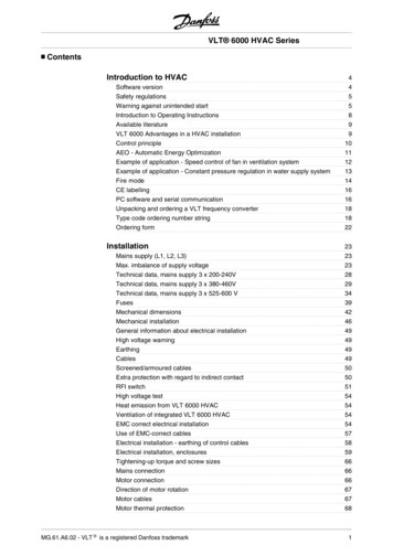
SafetyVLT 5000 Series175ZA438.17VLT 5000 SeriesOperating instructionsSoftware version: 3.7xThese operating instructions can be used for all VLT 5000Series frequency converters with software version 3.7x.The software version number can be seen from parameter 624.CE and C-tick labelling do not cover VLT 5001-5062,525-600 V units.cUL pending for VLT 5352-5552, 380-500 V.These Operating Instructions are a tool intended for persons who are to install, operate and programthe VLT 5000 Series.Operating Instructions:Gives instructions in optimum installation, commissioning and service.Design Guide:Gives all required information for design purposes, and gives a goodinsight into the technology, product range, technical data, etc.The Operating Instructions including Quick Setup are delivered with the unit.When reading these Operating Instructions, you will come across different symbols that require specialattention.The symbols used are the following:Indicates a general warningIndicates a high-voltage warningNB!:Indicates something to be noted by the readerMG.51.A8.02 - VLT is a registered Danfoss trademark3
VLT 5000 SeriesThe voltage of the frequency converteris dangerous whenever the equipmentis connected to mains. Incorrectinstallation of the motor or the frequency convertermay cause damage to the equipment, seriouspersonal injury or death.Consequently, the instructions in this manual,as well as national and local rules and safetyregulations, must be complied with. Warning against unintended start1. The motor can be brought to a stop bymeans of digital commands, bus commands,references or a local stop, while the frequencyconverter is connected to mains.If personal safety considerations make it necessaryto ensure that no unintended start occurs, thesestop functions are not sufficient.2. While parameters are being changed, the Safety regulationsmotor may start. Consequently, the stop key1. The frequency converter must be disconnected[STOP/RESET] must always be activated, followingfrom mains if repair work is to be carried out. Checkwhich data can be modified.that the mains supply has been disconnected3. A motor that has been stopped may start if faultsand that the necessary time has passed beforeoccur in the electronics of the frequency converter,removing motor and mains plugs.or if a temporary overload or a fault in the supply2. The [STOP/RESET] key on the control panel ofmains or the motor connection ceases.the frequency converter does not disconnect Installation of mechanical brakethe equipment from mains and is thus notto be used as a safety switch.Do not connect a mechanical brake to the output3. Correct protective earthing of the equipmentfrom the frequency converter before the relevantmust be established, the user must be protectedparameters for brake control are parameterised.against supply voltage, and the motor must be(Selection of output in parameter 319, 321,protected against overload in accordance with323 or 326 and cut-in current and frequencyapplicable national and local regulations.in parameter 223 and 225).4. The earth leakage currents are higher than 3.5 mA.5. Protection against motor overload is not included Use on isolated mainsin the factory setting. If this function is desired,See section RFI Switch regarding use on isolated mains.set parameter 128 to data value ETR tripIt is important to follow the recommendationsor data value ETR warning.regarding installation on IT-mains, since sufficientNote: The function is initialised at 1.16 x ratedprotection of the complete installation must bemotor current and rated motor frequency. Forobserved. Not taking care using relevant monitoringthe North American market: The ETR functionsdevices for IT-mains may result in damage.provide class 20 motor overload protectionin accordance with NEC.6. Do not remove the plugs for the motor and mainsupply while the frequency converter is connectedto mains. Check that the mains supply has beendisconnected and that the necessary time hasexpired before removing motor and mains plugs.7. Please note that the frequency converter hasmore voltage inputs than L1, L2 and L3, whenloadsharing (linking of DC intermediate circuit) andexternal 24 V DC have been installed. Checkthat all voltage inputs have been disconnectedand that the necessary time has passed beforerepair work is commenced.4MG.51.A8.02 - VLT is a registered Danfoss trademark
Touching the electrical parts may be fatal - even after the equipment hasbeen disconnected from mains.Also make sure that other voltage inputs have been disconnected, such asexternal 24 V DC, load-sharing (linkage of DC intermediate circuit), as wellas the motor connection for kinetic back-up.Using VLT 5001-5006, 200-240 V:wait at least 4 minutesUsing VLT 5008-5052, 200-240 V:wait at least 15 minutesUsing VLT 5001-5006, 380-500 V:wait at least 4 minutesUsing VLT 5008-5062, 380-500 V:wait at least 15 minutesUsing VLT 5072-5302, 380-500 V:wait at least 20 minutesUsing VLT 5352-5552, 380-500 V:wait at least 40 minutesUsing VLT 5001-5005, 525-600 V:wait at least 4 minutesUsing VLT 5006-5022, 525-600 V:wait at least 15 minutesUsing VLT 5027-5062, 525-600 V:wait at least 30 minutesUsing VLT 5042-5352, 525-690 V:wait at least 20 minutesMG.51.A8.02 - VLT is a registered Danfoss trademarkSafetyWarning:175ZA439.20VLT 5000 Series5
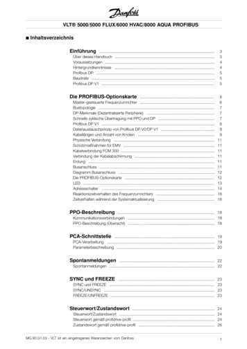
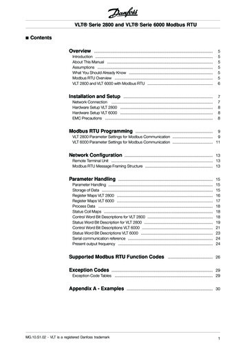
VLT 5000 Series Introduction to Quick SetupThis Quick Setup will guide you through EMC correctinstallation of the frequency converter by connectingpower, motor and control wiring (fig. 1). Start/stopof motor is to be done with the switch.For VLT 5122 - 5552 380 - 500 V, VLT 5032 5052 200 - 240 V AC and VLT 5042-5352, 525-690V, please refer to Technical data and Installationregarding mechanical and electrical installation.Fig. 1 1. Mechanical InstallationVLT 5000 frequency converters allow side-by-side mounting. The necessary cooling demands a free airpassage of 100 mm above and below the frequency converter (5016-5062 380-500 V, 5008-5027 200-240V and 5016-5062 525-600 V must have 200 mm, 5072-5102, 380-500 V 225 mm).Drill all holes by using the measurements stated in the table. Please note the difference in unit voltage.Place the frequency converter on the wall. Tighten up all four screws.All the below listed measurements are in mmVLT typeBookstyle IP 20, 200–240 V, (Fig. 2)A5001 - 50035004 - 5006Bookstyle IP 20, 380–500 V (Fig. 2)5001 - 50055006 - 5011Compact IP 54, 200–240 V (Fig. 3)5001 - 50035004 - 50065008 - 50115016 - 5027Compact IP 54, 380–500 V (Fig. 3)5001 - 50055006 - 50115016 - 50275032 - 50625072 - 5102Compact IP 20, 200–240 V (Fig. 4)5001 - 50035004 - 500650085011 - 50165022 - 5027Compact IP 20, 380–500 V (Fig. 4)5001 - 50055006 - 50115016 - 50225027 - 50325042 - 50625072 - 5102395395BCab90 260130 260384384707039539590 260130 0200200270330Fig. 2Fig. 3Fig. 46MG.51.A8.02 - VLT is a registered Danfoss trademark
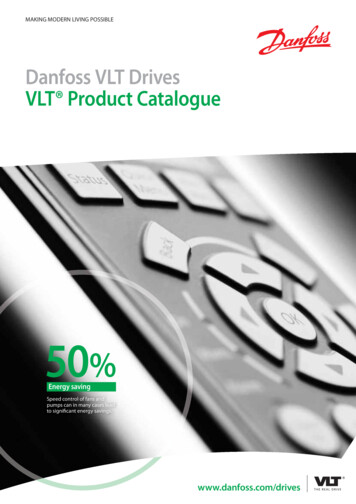
VLT 5000 Series 2. Electrical Installation, powerFig. 5Bookstyle IP 205001 - 5011 380 - 500 V5001 - 5006 200 - 240 VFig. 6Compact IP 20 and IP 545001 - 5011 380 - 500 V5001 - 5006 200 - 240 V5001 - 5011 525 - 600 VQuickSetupNOTE: The terminals are detachable on VLT 5001 - 5006, 200 - 240 V, VLT 5001 - 5011, 380 - 500V and VLT 5001 - 5011, 525 - 600 VConnect the mains supply to the mains terminals L1, L2, L3 of the frequency converter and to the earthconnection (fig. 5-8). Cable relief fitting is placed on the wall for Bookstyle units. Mount screened motorcable to the motor terminals U, V, W, PE of the frequency converter. Make sure, the screen is connectedelectrically to the drive.Fig. 7Compact IP 205016 - 5102 380 - 500 V5008 - 5027 200 - 240 V5016 - 5062 525 - 600 VFig. 8Compact IP 545016 - 5062 380 - 500 V5008 - 5027 200 - 240 VFig. 9Compact IP 545072 - 5102 380 - 500 VMG.51.A8.02 - VLT is a registered Danfoss trademark7
VLT 5000 Series 3. Electrical installation, control leadsUse a screw driver to remove the front coverunder the control panel.NOTE: The terminals are detachable. Connect ajumber between terminals 12 and 27 (Fig. 10)Mount screened cable to external start/stop ofcontrol terminals 12 and 18.Fig. 10 4. ProgrammingThe frequency converter is programmedover the control panel.Press the QUICK MENU button. The Quick Menuappears in the display. You choose parameters bymeans of arrow up and arrow down. Press theCHANGE DATA button to change parameter value.Data values are changed using the up and downarrows. Press the left or right buttons to move thecursor. Press OK to save your parameter setting.Set frequency interval and ramp times (Fig. 11)Min. referenceMax. referenceRamp up timeRamp down 08Set Operation site, Parameter 002 for Local.Set the desired language in parameter 001. Youhave six possibilities: English, German, French,Danish, Spanish and Italian.Set the motor parameters according to the equencycurrentmotor 102103104105106Fig. 11 5. Motor StartPress the START button to start the motor. Set motorspeed in Parameter 003. Check if the direction ofrotations is as shown in the display. It can be changedby swapping two phases of the motor cable.Press the STOP button to stop the motor.Select total or reduced Automatic Motor Adaption(AMA) in Parameter 107. For further description ofAMA, see section Automatic Motor Adaption, AMA.Press the START button to start the AutomaticMotor Adaption (AMA).Press the DISPLAY/STATUS button to leavethe Quick Menu.8MG.51.A8.02 - VLT is a registered Danfoss trademark
VLT 5000 Series Available literatureBelow is a list of the literature available for VLT5000. It must be noted that there may be deviationsfrom one country to another.Supplied with the unit:Operating instructions . MG.51.AX.YYHigh Power Installation Guide . MI.90.JX.YYCommunication with VLT 5000:VLTVLTVLTVLTVLT50005000500050005000Profibus manual . MG.10.EX.YYDeviceNet manual . MG.50.HX.YYLonWorks manual . MG.50.MX.YYModbus manual . MG.10.MX.YYInterbus manual . MG.10.OX.YYApplication options for VLT 5000:VLT 5000 SyncPos option manual . MG.10.EX.YYVLT 5000 Positioning controller manual . MG.50.PX.YYVLT 5000 Synchronising controller manual . MG.10.NX.YYRing spinning option . MI.50.ZX.02Wobble function option . MI.50.JX.02Winder and Tension control option . MG.50.KX.02Loadsharing . MI.50.NX.02VLT 5000 Brake resistors . MI.90.FX.YYBrake resistors for horizontal applications (VLT 5001 - 5011) (Only in English and German) . MI.50.SX.YYLC filter modules . MI.56.DX.YYConverter for encoder inputs (5V TTL to 24 V DC) (Only in combined English/German) . MI.50.IX.51Back Plate to VLT 5000 Series . MN.50.XX.02Various literature for VLT 5000:Design Guide .Incorporating a VLT 5000 Profibus in a Simatic S5 system .Incorporating a VLT 5000 Profibus in a Simatic S7 system .Hoist and the VLT 5000 series llaneous (only in English):Protection against electrical hazards . MN.90.GX.02Choice of prefuses . MN.50.OX.02VLT on IT mains . MN.90.CX.02Filtering of harmonic currents . MN.90.FX.02Handling aggressive environments . MN.90.IX.02CI-TITM contactors - VLT frequency converters . MN.90.KX.02VLT frequency converters and UniOP operator panels . MN.90.HX.02X version numberYY language versionMG.51.A8.02 - VLT is a registered Danfoss trademark9IntroductionInstructions for VLT 5000:
VLT 5000 Series General technical dataMains supply (L1, L2, L3):Supply voltage 200-240 V units . 3 x 200/208/220/230/240 V 10%Supply voltage 380-500 V units . 3 x 380/400/415/440/460/500 V 10%Supply voltage 525-600 V units . 3 x 525/550/575/600 V 10%Supply voltage 525-690 V units . 3 x 525/550/575/600/690 V 10%Supply frequency . 48-62 Hz /- 1 %See the section on special conditions in the Design GuideMax imbalance of supply voltage:VLT 5001-5011, 380-500 V and 525-600 V and VLT 5001-5006, 200-240 V . 2.0% of rated supply voltageVLT 5016-5062, 380-500 V and 525-600 V and VLT 5008-5027, 200-240 V . 1.5% of rated supply voltageVLT 5072-5552, 380-500 V and VLT 5032-5052, 200-240 V . 3.0% of rated supply voltageVLT 5042-5352, 525-690 V . 3.0% of rated supply voltageTrue Power factor (λ) . 0.90 nominal at rated loadDisplacement Power Factor (cos ϕ) . near unity ( 0.98)No. of switchings on supply input L1, L2, L3 . approx. 1 time/min.See the section on special conditions in the Design GuideVLT output data (U, V, W):Output voltage . 0-100% of supply voltageOutput frequency VLT 5001-5027, 200-240 V . 0-132 Hz, 0-1000 HzOutput frequency VLT 5032-5052, 200-240 V . 0-132 Hz, 0-450 HzOutput frequency VLT 5001-5052, 380-500 V . 0-132 Hz, 0-1000 HzOutput frequency VLT 5062-5302, 380-500 V . 0-132 Hz, 0-450 HzOutput frequency VLT 5352-5552, 380-500 V . 0-132 Hz, 0-300 HzOutput frequency VLT 5001-5011, 525-600 V . 0-132 Hz, 0-700 HzOutput frequency VLT 5016-5052, 525-600 V . 0-132 Hz, 0-1000 HzOutput frequency VLT 5062, 525-600 V . 0-132 Hz, 0-450 HzOutput frequency VLT 5042-5302, 525-690 V . 0-132 Hz, 0-200 HzOutput frequency VLT 5352, 525-690 V . 0-132 Hz, 0-150 HzRated motor voltage, 200-240 V units . 200/208/220/230/240 VRated motor voltage, 380-500 V units . 380/400/415/440/460/480/500 VRated motor voltage, 525-600 V units . 525/550/575 VRated motor voltage, 525-690 V units . 525/550/575/690 VRated motor frequency . 50/60 HzSwitching on output . UnlimitedRamp times . 0.05-3600 sec.Torque characteristics:Starting torque, VLT 5001-5027, 200-240 V and VLT 5001-5552, 380-500 V . 160% for 1 min.Starting torque, VLT 5032-5052, 200-240 V . 150% for 1 min.Starting torque, VLT 5001-5062, 525-600 V . 160% for 1 min.Starting torque, VLT 5042-5352, 525-690 V . 160% for 1 min.Starting torque . 180% for 0.5 sec.Acceleration torque . 100%Overload torque, VLT 5001-5027, 200-240 V and VLT 5001-5552, 380-500 V,VLT 5001-5062, 525-600 V, and VLT 5042-5352, 525-690 V . 160%Overload torque, VLT 5032-5052, 200-240 V . 150%Arresting torque at 0 rpm (closed loop) . 100%The torque characteristics given are for the frequency converter at the high overload torque level(160%). At the normal overload torque (110%), the values are lower.10MG.51.A8.02 - VLT is a registered Danfoss trademark
VLT 5000 SeriesBraking at high overload torque levelCycle time (s)Braking duty cycle at100% torque200-240 V5001-50275032-5052380-500 V5001-51025122-525253025352-5552525-600 V5001-5062525-690 V5042-5352Braking duty cycle at overtorque us40%40%10%6001) VLT 5502 at 90% torque. At 100% torque thebraking duty cycle is 13%. At mains rating 441-500V 100% torque the braking duty cycle is 17%.VLT 5552 at 80% torque. At 100% torquethe braking duty cycle is 8%.2) Based on 300 second cycle:For VLT 5502 the torque is 145%.For VLT 5552 the torque is 130%.Control card, digital inputs:Number of programmable digital inputs . 8Terminal nos. . 16, 17, 18, 19, 27, 29, 32, 33Voltage level . 0-24 V DC (PNP positive logics)Voltage level, logical ’0’ .
from mains if repair work is to be carried out. Check that the mains supply has been disconnected and that the necessary time has passed before removing motor and mains plugs. 2. The [STOP/RESET] key on the control panel of the frequency converter does not disconnect the equipment from mains and is thus not to be used as a safety switch. 3.