Transcription
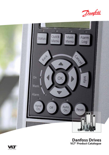
VLT 5000 SeriesContentsSafetySafety regulationsWarning against unintended startInstallation of mechanical brakeTechnical dataGeneral technical dataElectrical dataFusesDimensionsMechanical dimensionsInstallationMechanical installationElectrical installation - mains supplySafety groundingExtra protection (RCD)RFI switchInstallation of motor cablesConnection of motorDirection of motor rotationElectrical installation - brake cableElectrical installation - relay outputsElectrical installation - 24 Volt external DC supplyElectrical installation - load sharingElectrical installation - brake resistor temperature switchElectrical installation - bus connectionInstallation of control cablesConnection examplesOperation of the VLTControl panel (LCP)Control panel - displayControl panel - LEDsControl panel - control keysQuick SetupParameter selectionMenu modeManual initializationProgrammingOperation & DisplayMG.51.C5.22 - VLT is a registered Danfoss 6464656871717172727575757779791
VLT 5000 SeriesLoad and motorReferences and limitsParameters - Inputs and outputsSpecial functionsParameters - Serial communicationParameters - Technical functions and Display - Status messagesWarnings and alarmsWarningsExamples of useConveyor beltPumpGantry CraneTorque control, speed feedbackVLT 5000 controllersPID for process controlPID for speed controlPID for torque controller (open loop)EC/EMCCE labellingElectrical InstallationElectrical installation - EMC precautionsElectrical installation, selection of EMC-correct cablesList of functionsSetting of parametersLocal and remote controlControl with brake functionReferences - single referencesReferences - multi-referencesAutomatic Motor Adaptation, AMAMechanical brake controlPID for process controlPID for speed controlQuick dischargeFlying startNormal/high overload torque control,open loopProgramming of Torque limit and stopGalvanic Isolation (PELV)Extreme Running 202204206206207209MG.51.C5.22 - VLT is a registered Danfoss trademark.
VLT 5000 SeriesPeak voltage on motorSwitching on the inputMotor thermal protectionVibration and ShockAir HumidityAggressive environmentsEfficiencyInterference, Power aneous229Index232MG.51.C5.22 - VLT is a registered Danfoss trademark.3
VLT 5000 SeriesVLT 5000 SeriesInstruction ManualSoftware version: 3.9xThis Instruction Manual can be used for all VLT 5000 Series adjustable frequency drives with software version3.9x.The software version number can be seen from parameter 624.CE and C-tick labeling do not cover VLT 5001-5062, 525-600 V units.The VLT Adjustable Frequency Drive contains dangerous voltages when connected to line voltage. After disconnectingfrom the line wait at least 15 minutes before touching any electrical components.Also make sure that other voltage inputshave been disconnected, such as external24 VDC, load-sharing (linkage of DC intermediate circuit), as well as the motorconnection for kinetic back-up. Only acompetent electrician should carry out theelectrical installation. Improper installation of the motor or the VLT may causeequipment failure, serious injury or death.Follow this manual and National ElectricalCodes (NEC ) and local safety codes.It is the responsibility of the user or theperson installing the VLT to provide proper grounding, as well as motor overloadand branch circuit protection according tothe National Electrical Code (NEC ) andlocal codes.By altitudes above 2000 m, please contactDanfoss Drives regarding PELV.NOTEElectrostatic Precaution; Electrostatic discharge (ESD). Many electronic components are sensitive to static electricity.Voltages so low that they cannot be felt,seen or heard, can reduce the life, affectperformance, or completely destroy sensitive electronic components. When performing service, proper ESD equipmentshould be used to prevent possible damage from occurring.4MG.51.C5.22 - VLT is a registered Danfoss trademark.
VLT 5000 Series1.The frequency converter must be disconnected from mains if repair work is to be carriedout. Check that the mains supply has beendisconnected and that the necessary timehas passed before removing motor andmains plugs.2.The [STOP/RESET] key on the control panelof the frequency converter does not disconnect the equipment from mains and is thusnot to be used as a safety switch.3.4.5.Correct protective earthing of the equipmentmust be established, the user must be protected against supply voltage, and the motormust be protected against overload in accordance with applicable national and localregulations.The earth leakage currents are higher than3.5 mA.Protection against motor overload is not included in the factory setting. If this function isdesired, set parameter 128 to data value ETRtrip or data value ETR warning.Note: The function is initialised at 1.16 x ratedmotor current and rated motor frequency. Forthe North American market: The ETR functions provide class 20 motor overload protection in accordance with NEC.6.Do not remove the plugs for the motor andmain supply while the frequency converter isconnected to mains. Check that the mainssupply has been disconnected and that thenecessary time has expired before removingmotor and mains plugs.7.Please note that the frequency converter hasmore voltage inputs than L1, L2 and L3, whenloadsharing (linking of DC intermediate circuit) and external 24 V DC have been installed. Check that all voltage inputs have beendisconnected and that the necessary timehas passed before repair work is commenced.MG.51.C5.22 - VLT is a registered Danfoss trademark.Warning against unintended start1.The motor can be brought to a stop by meansof digital commands, bus commands, references or a local stop, while the adjustablefrequency drive is connected to the AC line.These stop functions are NOT sufficient toensure that no unintended start occures andshould NOT be used for personal safety considerations.2.While parameters are being changed, themotor may start. Consequently, the stop key"Stop/Reset" must always be activated, following which data can be modified.3.A motor that has been stopped may start iffaults occur in the electronics of the adjustable frequency drive, or if a temporary overload or a fault in the AC line supply or themotor connection ceases.Installation of mechanical brakeDo not connect a mechanical brake to the output fromthe frequency converter before the relevant parameters for brake control are parameterised.(Selection of output in parameter 319, 321, 323 or 326and cut-in current and frequency in parameter 223 and225).Use on isolated AC lineSee section RFI Switch regarding use on isolated ACline.It is important to follow the recommendations regarding installation on IT line, since sufficient protection ofthe complete installation must be observed. Not takingcare using relevant monitoring devices for IT line supply may result in damage.5SafetySafety regulations
VLT 5000 SeriesGeneral technical dataAC line supply (L1, L2, L3):Supply voltage 200-240 V unitsSupply voltage 380-500 V unitsSupply voltage 525-600 V unitsSupply voltage 525-690 V unitsSupply frequency3 x 200/208/220/230/240 V 10%3 x 380/400/415/440/460/500 V 10%3 x 525/550/575/600 V 10%3 x 525/550/575/600/690 V 10%48-62 Hz /- 1 %See the section on special conditions in the Design GuideMax. imbalance of supply voltage:VLT 5001-5011, 380-500 V and 525-600 V and VLT 5001-5006, 200-240 VVLT 5016-5062, 380-500 V and 525-600 V and VLT 5008-5027, 200-240 VVLT 5072-5500, 380-500 V and VLT 5032-5052, 200-240 VVLT 5075-5250, 525-600 VTrue Power factor (λ)Displacement Power Factor (cos ϕ)No. of switches on supply input L1, L2, L3Max. shortcircuit ratingVLT output data (U, V, W):Output voltageOutput frequency VLT 5001-5027, 200-240 VOutput frequency VLT 5032-5052, 200-240 VOutput frequency VLT 5001-5052, 380-500 VOutput frequency VLT 5062-5302, 380-500 VOutput frequency VLT 5352-5552, 380-500 VOutput frequency VLT 5001-5011, 525-600 VOutput frequency VLT 5016-5052, 525-600 VOutput frequency VLT 5062, 525-600 VOutput frequency VLT 5042-5302, 525-690 VOutput frequency VLT 5352-5602, 525-690 VRated motor voltage, 200-240 V unitsRated motor voltage, 380-500 V unitsRated motor voltage, 525-600 V unitsRated motor voltage, 525-690 V unitsRated motor frequencySwitching on outputRamp times0-100% of supply voltage0-132 Hz, 0-1000 Hz0-132 Hz, 0-450 Hz0-132 Hz, 0-1000 Hz0-132 Hz, 0-450 Hz0-132 Hz, 0-300 Hz0-132 Hz, 0-700 Hz0-132 Hz, 0-1000 Hz0-132 Hz, 0-450 Hz0-132 Hz, 0-200 Hz0-132 Hz, 0-150 Hz200/208/220/230/240 V380/400/415/440/460/480/500 V525/550/575 V525/550/575/690 V50/60 HzUnlimited0.05-3600 sec.Torque characteristics:Starting torque, VLT 5001-5027, 200-240 V and VLT 5001-5552, 380-500 VStarting torque, VLT 5032-5052, 200-240 VStarting torque, VLT 5001-5062, 525-600 VStarting torque, VLT 5042-5602, 525-690 VStarting torqueAcceleration torqueOverload torque, VLT 5001-5027, 200-240 V and VLT 5001-5552, 380-500 V,VLT 5001-5062, 525-600 V, and VLT 5042-5602, 525-690 V6 2.0% of rated supply voltage 1.5% of rated supply voltage 3.0% of rated supply voltage 3.0% of rated supply voltage0.90 nominal at rated loadnear unity ( 0.98)approx. 1 time/2 min.100,000 A160% for 1 min.150% for 1 min.160% for 1 min.160% for 1 min.180% for 0.5 sec.100%160%MG.51.C5.22 - VLT is a registered Danfoss trademark.
VLT 5000 SeriesOverload torque, VLT 5032-5052, 200-240 VArresting torque at 0 rpm (closed loop)150%100%The torque characteristics given are for the adjustable frequency drive at the high overload torque level (160%). Atthe normal overload torque (110%), the values are lower.200-240 V5001-50275032-5052380-500 V5001-51025122-525253025352-5552525-600 V5001-5062525-690 V5042-53525402-5602Braking duty cycle at 100% torque Braking duty cycle at over ntinuous40%60060040%40%3)10%10%4)Technical dataBraking at high overload torque levelCycle time (s)1) VLT 5502 at 90% torque. At 100% torque the braking duty cycle is 13%. At mains rating 441-500 V 100% torque the braking dutycycle is 17%.VLT 5552 at 80% torque. At 100% torque the braking duty cycle is 8%.2) Based on 300 second cycle:For VLT 5502 the torque is 145%.For VLT 5552 the torque is 130%.3) VLT 5502 at 80% torque.VLT 5602 at 71% torque.4) Based on 300 second cycle.For VLT 5502 the torque is 128%.For VLT 5602 the torque is 114%.Control card, digital inputs:Number of programmable digital inputsTerminal nos.Voltage levelVoltage level, logical '0'Voltage level, logical '1'Maximum voltage on inputInput resistance, RiScanning time per input816, 17, 18, 19, 27, 29, 32, 330-24 V DC (PNP positive logics) 5 V DC 10 V DC28 V DC2 kΩ3 msec.Reliable galvanic isolation: All digital inputs are galvanically isolated from the supply voltage (PELV). In addition, thedigital inputs can be isolated from the other terminals on the control card by connecting an external 24 V DC supplyand opening switch 4. VLT 5001-5062, 525-600 V do not meet PELV.Control card, analog inputs:No. of programmable analog voltage inputs/thermistor inputsTerminal nos.Voltage levelInput resistance, RiNo. of programmable analog current inputsTerminal no.Current rangeMG.51.C5.22 - VLT is a registered Danfoss trademark.253, 540 - 10 V DC (scalable)10 kΩ1600/4 - 20 mA (scalable)7
VLT 5000 Series200 Ω10 bit signMax. error 1% of full scale3 msec.55Input resistance, RiResolutionAccuracy on inputScanning time per inputTerminal no. groundReliable galvanic isolation: All analog inputs are galvanically isolated from the supply voltage (PELV)* as well as otherinputs and outputs.* VLT 5001-5062, 525-600 V do not meet PELV.Control card, pulse/encoder input:No. of programmable pulse/encoder inputsTerminal nos.Max. frequency on terminal 17Max. frequency on terminals 29, 32, 33Max. frequency on terminals 29, 32, 33Voltage levelVoltage level, logical '0'Voltage level, logical '1'Maximum voltage on inputInput resistance, RiScanning time per inputResolutionAccuracy (100-1 kHz), terminals 17, 29, 33Accuracy (1-5 kHz), terminal 17Accuracy (1-65 kHz), terminals 29, 33417, 29, 32, 335 kHz20 kHz (PNP open collector)65 kHz (Push-Pull)0-24 V DC (PNP positive logics) 5 V DC 10 V DC28 V DC2 kΩ3 msec.10 bit signMax. error: 0.5% of full scaleMax. error: 0.1% of full scaleMax. error: 0.1% of full scaleReliable galvanic isolation: All pulse/encoder inputs are galvanically isolated from the supply voltage (PELV)*. In addition, pulse and encoder inputs can be isolated from the other terminals on the control card by connecting anexternal 24 V DC supply and opening switch 4.* VLT 5001-5062, 525-600 V do not meet PELV.Control card, digital/pulse and analog outputs:No. of programmable digital and analog outputsTerminal nos.Voltage level at digital/pulse outputMinimum load to ground (terminal 39) at digital/pulse outputFrequency ranges (digital output used as pulse output)Current range at analog outputMaximum load to ground (terminal 39) at analog outputAccuracy of analog outputResolution on analog output.242, 450 - 24 V DC600 Ω0-32 kHz0/4 - 20 mA500 ΩMax. error: 1.5% of full scale8 bitReliable galvanic isolation: All digital and analog outputs are galvanically isolated from the supply voltage (PELV)*, aswell as other inputs and outputs.* VLT 5001-5062, 525-600 V do not meet PELV.Control card, 24 V DC supplyTerminal nos.Max. load (short-circuit protection)812, 13200 mAMG.51.C5.22 - VLT is a registered Danfoss trademark.
VLT 5000 SeriesTerminal nos. ground20, 39Reliable galvanic isolation: The 24 V DC supply is galvanically isolated from the supply voltage (PELV)*, but has thesame potential as the analog outputs.* VLT 5001-5062, 525-600 V do not meet PELV.Control card, RS 485 serial communication:Terminal nos.68 (TX , RX ), 69 (TX-, RX-)Relay outputs: 1)No. of programmable relay outputsTerminal nos., control card (resistive load only)Max. terminal load (AC1) on 4-5, control cardMax. terminal load (DC1 (IEC 947)) on 4-5, control cardMax. terminal load (DC1) on 4-5, control card for UL/cUL applicationsTerminal nos., power card (resistive and inductive load)Max. terminal load (AC1) on 1-3, 1-2, power cardMax. terminal load (DC1 (IEC 947)) on 1-3, 1-2, power cardMin. terminal load (AC/DC) on 1-3, 1-2, power card24-5 (make)50 V AC, 1 A, 50 VA25 V DC, 2 A / 50 V DC, 1 A, 50 W30 V AC, 1 A / 42.5 V DC, 1A1-3 (break), 1-2 (make)250 V AC, 2 A, 500 VA25 V DC, 2 A / 50 V DC, 1A, 50 W24 V DC, 10 mA / 24 V AC, 100 mA1) Rated values for up to 300,000 operations.At inductive loads, the number of operations are reduced by 50%, alternatively the current can be reduced by50%, thus the 300,000 operations are maintained.Brake resistor terminals (only SB, EB, DE and PB units):Terminal nos.External 24 Volt DC supply:Terminal nos.Voltage rangeMax. voltage ripplePower consumptionMin. pre-fuse81, 8235, 3624 V DC 15% (max. 37 V DC for 10 sec.)2 V DC15 W - 50 W (50 W for start-up, 20 msec.)6 AmpReliable galvanic isolation: Full galvanic isolation if the external 24 V DC supply is also of the PELV type.MG.51.C5.22 - VLT is a registered Danfoss trademark.9Technical dataReliable galvanic isolation: Full galvanic isolation.
VLT 5000 SeriesCable lengths, cross-sections and connectors:Max. motor cable length, screened cable150 mMax. motor cable length, unscreened cable300 mMax. motor cable length, screened cable VLT 5011 380-500 V100 mMax. motor cable length, screened cable VLT 5011 525-600 V and VLT 5008, normal overload mode,525-600 V50 mMax. brake cable length, screened cable20 mMax. loadsharing cable length, screened cable25 m from drive to DC bar.Max. cable cross-section for motor, brake and loadsharing, see Electrical dataMax. cable cross-section for 24 V external DC supply- VLT 5001-5027 200-240 V; VLT 5001-5102 380-500 V; VLT 5001-5062 525-600 V- VLT 5032-5052 200-240 V; VLT 5122-5552 380-500 V; VLT 5042-5602 525-690 VMax. cross-section for control cablesMax. cross-section for serial communication4 mm2 /10 AWG2.5 mm2 /12 AWG1.5 mm 2 /16 AWG1.5 mm2 /16 AWGIf UL/cUL is to be complied with, cable with temperature class 60/75 C must be used(VLT 5001 - 5062 380 - 500 V, 525 - 600 V and VLT 5001 - 5027 200 - 240V).If UL/cUL is to be complied with, cable with temperature class 75 C must be used(VLT 5072 - 5552 380 - 500 V, VLT 5032 - 5052 200 - 240 V, VLT 5042 - 5602 525 - 600 V).Connectors are for use of both copper and aluminium cables, unless other is specified.Accuracy of display readout (parameters 009-012):Motor current [6] 0-140% loadTorque % [7], -100 - 140% loadOutput [8], power HP [9], 0-90% loadControl characteristics:Frequency rangeResolution on output frequencySystem response timeSpeed, control range (open-loop)Speed, control range (closed-loop)Speed, accuracy (open-loop)Speed, accuracy (closed-loop)Torque control accuracy (open-loop)Torque control accuracy (speed feedback)Max. error: 2.0% of rated output currentMax. error: 5% of rated motor sizeMax. error: 5% of rated output0 - 1000 Hz 0.003 Hz3 msec1:100 of synchro. speed1:1000 of synchro. speed 1500 rpm: max. error 7.5 rpm 1500 rpm: max. error 1.5 rpm0-150 rpm: max. error 20% of rated torqueMax. error 5% of rated torqueAll control characteristics are based on a 4-pole asynchronous motorExternals:Enclosure (dependent on power size)Chassis, Nema1, Nema12Vibration test0.7 g RMS 18-1000 Hz random. 3 directions for 2 hours (IEC 68-2-34/35/36)Max. relative humidity93 % (IEC 68-2-3) for storage/transportMax. relative humidity95 % non condensing (IEC 721-3-3; class 3K3) for operationAggresive environment (IEC 721 - 3 - 3)Uncoated class 3C2Aggresive environment (IEC 721 - 3 - 3)Coated class 3C3Ambient temperature Chassis, NEMA 1(high overload torque 160%)Max. 45 C (24-hour average max. 40 C)Ambient temperature Chassis, NEMA 1(normal overload torque 110%) Max. 40 C (24-hour average max. 35 C)Ambient temperature NEMA 12 (high overload torque 160%)Max. 40 C (24-hour average max. 35 C)10MG.51.C5.22 - VLT is a registered Danfoss trademark.
VLT 5000 SeriesAmbient temperature NEMA 12 (normal overload torque 110%)Ambient temperature NEMA 1/NEMA 121VLT 5011 500 VAmbient temperature NEMA 12 VLT 5042-5602, 525-690 V; and5122-5552, 380-500 V (high overload torque 160%)Max. 40 C (24-hour average max. 35 C)Max. 40 C (24-hour average max. 35 C)Max. 45 C (24-hour average max. 40 C)Derating for high ambient temperature, see the Design Guide0 C-10 C-25 - 65/70 C1000 mMin. ambient temperature in full operationMin. ambient temperature at reduced performanceTemperature during storage/transportMax. altitude above sea levelEMC standards applied, EmissionEMC standards applied, ImmunityEN 61000-6-3, EN 61000-6-4, EN 61800-3, EN 55011EN 61000-6-2, EN 61000-4-2, EN 61000-4-3, EN 61000-4-4EN 61000-4-5, EN 61000-4-6, VDE 0160/1990.12VLT 5001-5062, 525 - 600 V do not comply with EMC or Low Voltage Directives.MG.51.C5.22 - VLT is a registered Danfoss trademark.11Technical dataDerating for altitude over 1000 m above sealevel, see the Design Guide
VLT 5000 SeriesVLT 5000 Series protection: Electronic motor thermal protection against overload. Temperature monitoring of heat-sink ensures that the drive cuts out if the temperature reaches 90 C forChassis and Nema 1. For NEMA 12 cut-out temperature is 80 C. An overtemperature can only be reset whenthe temperature of the heat-sink has fallen below 60 C.For the units mentioned below, the limits are as follows:- VLT 5122, 380-500 V, cuts out at 75 C and can be reset if the temperature has fallen below 60 C.- VLT 5152, 380-500 V, cuts out at 80 C and can be reset if the temperature has fallen below 60 C.- VLT 5202, 380-500 V, cuts out at 95 C and can be reset if the temperature has fallen below 65 C.- VLT 5252, 380-500 V, cuts out at 95 C and can be reset if the temperature has fallen below 65 C.- VLT 5302, 380-500 V, cuts out at 105 C and can be reset if the temperature has fallen below 75 C.- VLT 5352-5552, 380-500 V, cut out at 85 C and can be reset if the temperature has fallen below 60 C.- VLT 5042-5122, 525-690 V, cut out at 75 C and can be reset if the temperature has fallen below 60 C.- VLT 5152, 525-690 V, cuts out at 80 C and can be reset if the temperature has fallen below 60 C.- VLT 5202-5352, 525-690 V, cut out at 100 C and can be reset if the temperature has fallen below 70 C.- VLT 5402-5602, 525-690 V, cut out at 75 C and can be reset if the temperature has fallen below 60 C. The drive is protected against short-circuiting on motor terminals U, V, W. The drive is protected against earth fault on motor terminals U, V, W. Monitoring of the intermediate circuit voltage ensures that the drive cuts out if the intermediate circuit voltagegets too high or too low. If a motor phase is missing, the drive cuts out, see parameter 234 Motor phase monitor. If there is a mains fault, the drive is able to carry out a controlled deramping. If a mains phase is missing, the drive will cut out when a load is placed on the motor.12MG.51.C5.22 - VLT is a registered Danfoss trademark.
VLT 5000 SeriesAccording to international requirementsOutput currentOutput (240 V)Typical shaft outputTypical shaft outputVLT typeIVLT,N [A]IVLT, MAX (60 s) [A]SVLT,N [kVA]PVLT,N [kW]PVLT,N [HP]Max. cable cross-section to motor,brake and loadsharing [mm 2 ]/[AWG]2 )50013.75.91.50.7514/10(200 V)IL,N [A]Rated input current3.4Max. cable4/10cross-section power [mm2 ]/[AWG] 2 )1)Max. pre-fuses16/10[-]/UL [A]0.95Efficiency3)Weight IP 20 EB Bookstyle[kg]7Weight IP 20 EB Compact [kg]8Weight IP 54 Compact[kg]11.5Power loss at[W]58max. load.IP 172194IP 20/IP54IP 20/IP54IP 20/IP54IP 20/IP54IP 20/IP541. For type of fuse see section Fuses.2. American Wire Gauge.3. Measured using 30 m screened motor cables at rated load and rated frequency.MG.51.C5.22 - VLT is a registered Danfoss trademark.13Technical dataBookstyle and Compact, Mains supply 3 x 200 240 VElectrical data
VLT 5000 SeriesCompact, AC line supply 3 x 200-240 VAccording to international requirementsVLT typeNormal overload torque (110 %):IVLT,N [A]Output currentIVLT, MAX (60 s)[A]Output (240 V)SVLT,N [kVA]PVLT,N [kW]Typical shaft outputPVLT,N [HP]Typical shaft outputHigh overload torque (160 %):IVLT,N [A]Output currentIVLT, MAX (60 s)[A]Output (240 V)SVLT,N [kVA]PVLT,N [kW]Typical shaft outputPVLT,N [HP]Typical shaft outputMax. cable cross-section to motor,IP 54IP 20brake and load sharing [mm2 /AWG]2) 5)Min. cable cross-section to motor, brake andload sharing4) [mm2 /AWG]2)(200 V) IL,N [A]Rated input currentMax. cable cross-section,IP 54IP 20power [mm2 ]/[AWG]2) 5)Max. pre-fuses[-]/UL1) [A]Efficiency3)Weight IP 20 EB[kg]Weight IP 54[kg]Power loss at max. load.[W]- high overload torque(160 %)- normal overload torque [W](110 1016/6 16/616/6 /8 10/810/810/816/6324616/6 16/616/6 442654578310421243IP 20/IP 54IP 20/IP 54IP 20/IP 54IP 20/IP 54IP 20/IP 541. For type of fuse, see section Fuses.2. American Wire Gauge.3. Measured using 100 ft [30 m] shielded motor cables at rated load and rated frequency.4. Min. cable cross-section is the smallest cable cross-section allowed to be fitted on the terminals to comply with IP 20. Always complywith national and local regulations on min. cable cross-section.5. Aluminum cables with cross-section above 0.054 in2 [35 mm2] must be connected by use of an AI-Cu connector.14MG.51.C5.22 - VLT is a registered Danfoss trademark.
VLT 5000 SeriesCompact, AC line supply 3 x 200-240 VOutputTypical shaft outputTypical shaft outputHigh overload torque (160 %):Output currentOutputTypical shaft outputMax. cable cross-section to motorand load sharingMax. cable cross-section to brakeNormal overload torque (110 %):Rated input currentNormal overload torque (150 %):Rated input currentMax. cable cross-sectionpower supplyMin. cable cross-section to motor,powersupply, brake and load sharingVLT type503250425052IVLT,N [A] (200-230 V)IVLT, MAX (60 s) [A] (200-230 V)IVLT,N [A] (231-240 V)IVLT, MAX (60 s) [A] (231-240 V)SVLT,N [kVA] (208 V)SVLT,N [kVA] (230 V)SVLT,N [kVA] (240 V)[HP] (208 V)[kW] (230 8715417061686460451151731042854146434030120300 mcm2541432151301955257545037126.6149.9101,3120300 mcm68126,6200/200250/250IVLT,N [A] (200-230 V)IVLT, MAX [A] (200-230 V)IVLT,N [A] (231-240 V)IVLT, MAX [A] (231-240 V)SVLT,N [kVA] (208 V)SVLT,N [kVA] (230 V)SVLT,N [kVA] (240 V)[HP] (208 V)[kW] (230 V)[mm2 ]4,6[AWG]2,4,6[mm2 ]4,6[AWG]2,4,6IL,N [A] (230 V)IL,N [A] (230 35333022101.377,9150/150Max. pre-fuses (line) [-]/UL[A]1Efficiency30,96-0,9710891361Normal overload [W]High overload [W]8381089101101IP 00 [kg]IP 20 Nema1 [kg]101101IP 54 Nema12 [kg]104104IP 00 / Nema 1 (IP 20) / IP 54Power lossWeightWeightWeightEnclosureTechnical dataAccording to international requirementsNormal overload torque (110 %):Output current161213611011011041. For type of fuse, see section Fuses.2. American Wire Gauge.3. Measured using 100 ft [30 m] shielded motor cables at rated load and rated frequency.4. Max. cable cross-section is the maximum possible cable cross-section allowed to be fitted on the terminals. Min. cable cross-sectionis the minimum allowed cross-section. Always comply with national and local regulations on min. cable cross-section.5. Weight without shipping container.6. Connection stud: M8 Brake: M6.MG.51.C5.22 - VLT is a registered Danfoss trademark.15
VLT 5000 SeriesBookstyle and Compact, Mains supply 3 x 380 - 500 VAccording to international requirementsOutput currentVLT typeIVLT,N [A] (380-440 V)IVLT, MAX (60 s) [A] (380-440 V)IVLT,N [A] (441-500 V)IVLT, MAX (60 s) [A] (441-500 V)SVLT,N [kVA] (380-440 V)OutputSVLT,N [kVA] (441-500 V)PVLT,N [kW]Typical shaft outputPVLT,N [HP]Typical shaft outputMax. cable cross-section to motor,brake and loadsharing [mm2 ]/[AWG]2 )Rated input currentMax. cable cross-section, power [mm2 ]/[AWG]2)Max. pre-fuses [-]/UL1) [A]Efficiency 3)Weight IP 20 EB Bookstyle [kg]Weight IP 20 EB Compact [kg]Weight IP 54 Compact [kg]Power loss at max. loadEnclosure50012.23.51.931.71.60.7514/10IL,N [A] (380 V) 2.3IL,N [A] (460 V) 1.94/1016/60.967811.5[W] 55IP 20/IP 967811.567IP 20/IP 234/104/103.83.44/1016/100.967811.592IP 20/IP 545.34.84/1016/100.967.58.512110IP 20/IP 541. For type of fuse see section Fuses.2. American Wire Gauge.3. Measured using 30 m screened motor cables at rated load and rated frequency.16MG.51.C5.22 - VLT is a registered Danfoss trademark.
VLT 5000 SeriesAccording to international requirementsOutput currentVLT typeIVLT,N [A] (380-440 V)IVLT, MAX (60 s) [A] (380-440 V)IVLT,N [A] (441-500 V)IVLT, MAX (60 s) [A] (441-500 V)OutputSVLT,N [kVA] (380-440 V)SVLT,N [kVA] (441-500 V)PVLT,N [kW]Typical shaft outputPVLT,N [HP]Typical shaft outputMax. cable cross-section to motor,brake and loadsharing [mm2 ]/[AWG]2 )50057.211.56.310.15.55.53.044/10IL,N [A] (380 V) 7IL,N [A] (460 V) 64/10Max. cable cross-section power [mm2 ]/[AWG]2)16/15Max. pre-fuses [-]/UL1) [A]0.96Efficiency 3)Weight IP 20 EB Bookstyle [kg]7.5Weight IP 20 EB Compact [kg]8.5Weight IP 54 EB Compact [kg]12Power loss at max. load.[W] 139IP 20/EnclosureIP 54Rated input 00.969.510.514198IP 20/IP 50IP 20/IP 5415.014.04/1035/300.969.510.514295IP 20/IP 541. For type of fuse see section Fuses.2. American Wire Gauge.3. Measured using 30 m screened motor cables at rated load and rated frequency.MG.51.C5.22 - VLT is a registered Danfoss trademark.17Technical dataBookstyle and Compact, Mains supply 3 x 380 - 500 V
VLT 5000 SeriesCompact, AC line supply 3 x 380-500 VAccording to international requirementsNormal overload torque (110 %):Output currentOutputTypical shaft outputTypical shaft outputHigh overload torque (160 %):Output currentOutputVLT type501650225027IVLT,N [A] (380-440 V)IVLT, MAX (60 s) [A] (380-440 V)IVLT,N [A] (441-500 V)IVLT, MAX (60 s) [A] (441-500 V)SVLT,N [kVA] (380-440 V)SVLT,N [kVA] (441-500 V)PVLT,N [kW]PVLT,N .418.5254448.441.445.533.535.82230IVLT,N [A] (380-440 V)IVLT, MAX (60 s) [A] (380-440 V)IVLT,N [A] (441-500 V)IVLT, MAX (60 s) [A] (441-500 V)SVLT,N [kVA] (380-440 V)SVLT,N [kVA] (441-500 V)PVLT,N [kW]PVLT,N 559IP 20/IP 54559655IP 20/IP 54655768IP 20/IP 54Typical shaft outputTypical shaft outputMax. cable cross-section to motor,brake and load sharing [mm2 ]/[AWG]2)Min. cable cross-section to motor,brake and load sharing [mm2]/[AWG]2) 4)Rated input currentMax. cable cross-section,power [mm 2 ]/[AWG]Max. pre-fusesEfficiency3)Weight IP 20 EBWeight IP 54Power loss at max. load.- high overload torque (160 %)- normal overload torque (110 %)EnclosureIP 54IP 20IL,N [A] (380 V)IL,N [A] (460 V
ted from mains if repair work is to be carried out. Check that the mains supply has been disconnected and that the necessary time has passed before removing motor and mains plugs. 2. The [STOP/RESET] key on the control panel of the frequency converter does not discon-nect the equipment from mains and is thus not to be used as a safety switch. 3.