Transcription
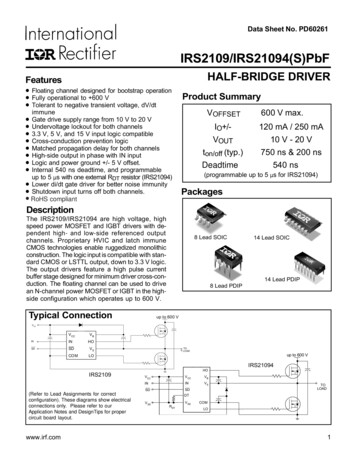
Zero Drift, High Voltage, Low Power,Programmable Gain Instrumentation AmplifierADA4254Data SheetSIMPLIFIED FUNCTIONAL BLOCK DIAGRAMAPPLICATIONSUniversal process control front endsData acquisition systemsTest and measurement systemsGENERAL DESCRIPTIONThe ADA4254 is a zero drift, high voltage, low powerprogrammable gain instrumentation amplifier (PGIA) designedfor process control and industrial applications. The ADA4254features 12 binary weighted gains ranging from 1/16 V/V to128 V/V and three scaling gain options of 1 V/V, 1.25 V/V, and1.375 V/V, resulting in 36 possible gain settings. The powerconsumption of the ADA4254 is a mere 22 mW, making thedevice an excellent choice for industrial systems that demandprecision, robustness, and low power.The zero drift amplifier topology of the ADA4254 self calibratesdc errors and low frequency 1/f noise, achieving excellent dcprecision over the entire specified temperature range. This highlevel of precision maximizes dynamic range and greatly reducescalibration requirements in many applications.Rev. BVDDHIOUT HVEXCITATIONCURRENTSADA4254AVDDIOUT LV IN1–IN1 IN2–IN2 –ROUT–EMI FILTER–OUT VOCMRIN – OUT– ROUTAVSSDIGITAL CONTROL7 GPIOSPI INTERFACEDVDDDVSS15741-001Optimized for ADC synchronizationLow power: 22 mW ( 12 V supplies)12 binary gain steps from 1/16 V/V to 128 V/V3 scaling gains: 1 V/V, 1.25 V/V, and 1.375 V/V 60 V protected input multiplexerExcellent dc precisionLow input offset voltage: 14 μV maximumLow input offset voltage drift: 0.08 μV/ C maximumGain calibration via ROMLow gain drift: 1 ppm/ C maximumHigh CMRR: 116 dB minimum, G 1 V/VLow input bias current: 1.5 nA maximumHigh input impedanceIntegrated input EMI filteringWide input supply range: 5 V to 28 VDedicated output amplifier supplies7 GPIO ports with special functionsSequential chip select modeExternal multiplexer controlExcitation current sourcesSPI port with checksum (CRC) supportInternal fault detectionWire break test currentsOn-chip test multiplexer28-lead, 5 mm 5 mm LFCSP, 24-lead TSSOPSpecified temperature range: 40 C to 105 C 60V OVERVOLTAGEPROTECTED MUXFEATURESVSSHFigure 1.The input multiplexer provides 60 V protection to the highimpedance inputs of the amplifier, while providing thecapability to switch between two input sources. In addition,integrated electromagnetic interference (EMI) filters blockharsh RF noise from the sensitive inputs of the amplifier.Various safety features on the ADA4254 detect both internaland external faults. The serial port interface (SPI) supportscyclical redundancy check (CRC) error detection to ensurerobust communication. These safety features ease system safetyintegrity level (SIL) certification.Seven general-purpose input/output (GPIO) pins, which can beconfigured to provide various special functions, are included inthe ADA4254. An excitation current source output is availableto bias sensors such as resistance temperature detectors (RTDs).The ADA4254 is specified over the 40 C to 105 C temperaturerange and is offered in a compact 5 mm 5 mm, 28-lead LFCSPand a 24-lead TSSOP.COMPANION PRODUCTSADCs: AD4007, AD7768, AD7175-2ADC Drivers: ADA4945-1, LTC6363Voltage References: ADR4550, ADR3450, LT6656Document FeedbackInformation furnished by Analog Devices is believed to be accurate and reliable. However, noresponsibility is assumed by Analog Devices for its use, nor for any infringements of patents or otherrights of third parties that may result from its use. Specifications subject to change without notice.No license is granted by implication or otherwise under any patent or patent rights of AnalogDevices. Trademarks and registered trademarks are the property of their respective owners.One Technology Way, P.O. Box 9106, Norwood, MA 02062-9106, U.S.A.Tel: 781.329.4700 2019–2020 Analog Devices, Inc. All rights reserved.Technical Supportwww.analog.com
ADA4254Data SheetTABLE OF CONTENTSFeatures . 1SPI Read/Write Error Detection . 35Applications . 1SPI Command Length Error Detection . 35General Description . 1Applications Information . 36Simplified Functional Block Diagram . 1Input and Output Offset Voltage and Noise . 36Companion Products . 1ADC Clock Synchronization . 36Revision History . 3Specifications . 4Programmable Logic Controller (PLC) Voltage/CurrentInput . 37Timing Specifications . 83-Wire RTD With Current Excitation . 38Absolute Maximum Ratings . 9High Rail Current Sensing . 39Thermal Resistance . 9Register Summary . 40ESD Caution. 9Register Details . 42Pin Configurations and Function Descriptions . 10GAIN MUX Register Details . 42Typical Performance Characteristics . 11Software Reset Register (Reset) Details . 43Theory of Operation . 23Clock Synchronization Configuration Register (SYNC CFG)Details . 44Programmable Gain Instrumentation Amplifier . 23Input Multiplexer . 24EMI Reduction and Internal EMI Filter . 24Input Amplifier. 25Output Amplifier. 25Power Supplies . 26ESD Map . 26Output Ripple Calibration Configuration . 27General-Purpose Inputs/Outputs (GPIOs) . 27Excitation Currents . 27External Clock Synchronization . 28Sequential Chip Select (SCS) . 28Gain Error Calibration . 30Digital Error Register (DIGITAL ERR) Details. 45Analog Error Register (ANALOG ERR) Details . 46GPIO Data Register (GPIO DATA) Details . 47Internal Mux Control Register (INPUT MUX) Details . 48Wire Break Detect Register (WB DETECT) Details . 49GPIO Direction Register (GPIO DIR) Details . 50Sequential Chip Select Register (SCS) Details. 50Analog Error Mask Register (ANALOG ERR DIS) Details . 51Digital Error Mask Register (DIGITAL ERR DIS) Details . 52Special Function Configuration Register (SF CFG) Details . 53Error Configuration Register . 54Test Multiplexer Register (TEST MUX) Details . 55Wire Break Detection . 31Excitation Current Configuration Register(EX CURRENT CFG) Details . 56Test Multiplexer . 32Gain Calibration Registers (GAIN CALx) Details . 57External Mux Control. 32Trigger Calibration Register (TRIG CAL) Details . 58Digital Interface . 33Master Clock Count Register (M CLK CNT) Details. 58SPI Interface . 33Accessing the ADA4254 Register Map . 33DIE Revision Identification Register (DIE REV ID) Details. 58Checksum Protection . 33Device Identification Registers (PART ID) Details . 58CRC Calculation . 35Outline Dimensions . 59Memory Map Checksum Protection . 35Ordering Guide . 59Read-Only Memory (ROM) Checksum Protection . 35Rev. B Page 2 of 59
Data SheetADA4254REVISION HISTORY6/2020—Rev. A to Rev. BChanges to Figure 10 . 11Changes to Figure 23 . 13Changes to Figure 37 . 16Change to Input Multiplexer Section. 24Changes to External Clock Synchronization Section . 28Change to Wire Break Detection Section . 31Changes to Figure 100 . 36Change to 3-Wire RTD with Current Excitation Section . 38Change to Table 21. 49Change to Bits[7:0], DIE REV ID[7:0]—Die RevisionIdentification Number Section . 5811/2019—Rev. 0 to Rev. AChanges to Features Section and General Description Section . 1Changes to Static Power Dissipation Parameter, Table 1 . 7Changes to 3-Wire RTD With Current Excitation Section . 3811/2019—Revision 0: Initial VersionRev. B Page 3 of 59
ADA4254Data SheetSPECIFICATIONSTA 25 C, VDDH 28 V, VSSH 28 V, AVDD 5 V, AVSS 0 V, DVDD 3.3 V, DVSS 0 V, VOCM AVDD/2, and no load,unless otherwise noted.Table 1.ParameterOFFSET VOLTAGEDifferential Offset VoltageInput Offset Voltage (VOSI)Output Offset Voltage (VOSO)Differential Offset VoltageDriftVOSI/TVOSO/TDifferential Offset Voltage vs.VDDH and VSSH (PowerSupply Rejection Ratio(PSRR)), RTIGain (G) 1/16 V/VG 1 V/VG 128 V/VDifferential Offset Voltage vs.AVDD (PSRR), RTIG 1/16 V/VG 1 V/VG 128 V/VDifferential Offset vs. ExternalClock Frequency, RTIG 1/16 V/VG 1 V/VG 128 V/VCOMMON–MODE REJECTIONRATIO (CMRR), RTICMRR to 60 HzG 1/16 V/VG 1 V/VG 128 V/VG 1/16G 1G 128Test Conditions/CommentsTotal offset, referred to input (RTI) VOSI VOSOGainMinTypMaxUnit 3 40 14 125μVμV 0.03 0.98 0.08 2.5μV/ CμV/ CTA 40 C to 105 C1, total offset drift,RTI VOSI/T VOSO / TGainVDDH VSSH 10 V to 56 V8011014090120154dBdBdB669011876100136dBdBdB 0.2 0.1 D AVSS 2.7 V to 5.5 VClock frequency 0.8 MHz to 1.2 MHz IN IN 25 V to 25 V, scaling gain 1 V/V9211614088112136TA 40 C to 105 C1TA 40 C to 105 C1TA 40 C to 105 C1Rev. B Page 4 of 59
Data SheetParameterGAINInput Gain RangeOutput Gain RangeGain ErrorBefore CalibrationUsing CalibrationCoefficientAll Gain Values Except asFollows:G 1/16 V/V, All ScalingGainsG 32 V/V, 64 V/V, AllScaling GainsG 128 V/V, Scaling Gains1 V/V, 1.25 V/VG 128 V/V, Scaling Gain1.375 V/VNonlinearityNOISEADA4254Test Conditions/CommentsOutput voltage (VOUT) 8.5 V p-p2MinTyp1/16 to 1281, 1.25, 1.375V/VV/V 0.06 0.01 0.12 0.025%%TA 40 C to 105 C1 0.3 1ppm/ CTA 40 C to 105 C1 0.8 1.5ppm/ CTA 40 C to 105 C1 0.4 1.5ppm/ CTA 40 C to 105 C1 0.6 2ppm/ CTA 40 C to 105 C1 0.7 2.5ppm/ CAll gains except 32 V/V, 64 V/V and 128 V/V2, 3G 32 V/VG 64 V/VG 128 V/V57.5121515ppmppmppmppmTotal noise, RTI e 2 eno ni Gain 217253nV/ HznV/ Hz955.75330μV p-pμV p-pnV p-p1006.8395μV p-pμV p-pnV p-p1003.14fA/ HzpA p-ppA p-p 0.45TA 40 C to 85 C1TA 40 C to 105 C1Input Offset CurrentInput Operating Voltage RangeMUX OVER VOLT ERRPositive ThresholdNegative ThresholdINPUT ERR/GAIN RSTPositive ThresholdNegative ThresholdUnitAll GainsAll GainsVoltage Noise, 1 kHz, RTIInput Noise (eni)Output Noise (eno)0.1 Hz to 10 Hz, RTIG 1/16 V/VG 1 V/VG 128 V/V0.01 Hz to 10 Hz, RTIG 1/16 V/VG 1 V/VG 128 V/VCurrent Noise10 Hz0.1 Hz to 10 Hz0.01 Hz to 10 HzINPUT CHARACTERISTICSInput Bias CurrentInput ImpedanceMax 0.2TA 40 C to 85 C1TA 40 C to 105 C1Common modeDifferentialGuaranteed by CMRR 1.5 4 14 1.3 2.5 3.5 1 11 1 4.7VSSH 3Rev. B Page 5 of 59VDDH 3nAnAnAnAnAnAGΩ pFGΩ pFVVDDH 0.9VSSH 0.9VVVDDH 1.5VSSH 1.5VV
ADA4254ParameterANALOG OUTPUTSOutput Voltage Swing fromEach RailCapacitive Load DriveShort-Circuit CurrentOUTPUT ERRPositive ThresholdNegative ThresholdVOCM DYNAMIC PERFORMANCE 3 dB BandwidthSlew RateVoltage NoiseGainVOCM INPUT CHARACTERISTICSInput Voltage RangeInput ResistanceCommon Mode Offset VoltageCommon Mode OffsetVoltage DriftInput Bias CurrentDYNAMIC RESPONSESmall Signal 3 dB BandwidthG 1/16 V/VG 1/8 V/VG 1/4 V/VG 1/2 V/VG 1 V/VG 2 V/VG 4 V/VG 8 V/VG 16 V/VG 32 V/VG 64 V/VG 128 V/VSettling Time 0.01%G 1 V/VG 8 V/VG 128 V/VSettling Time 0.0015% (16-Bit)G 1 V/VG 8 V/VG 128 V/VSlew RateG 1/16 V/VG 1 V/VG 128 V/VData SheetTest Conditions/CommentsMinAVDD 5 V, load resistor (RL) 2.49 kΩ to 2.5 VAVSS 0.06AVDD 2.7 V, RL 1.8 kΩ to 1.35 VAVSS 0.05To 2.5 V, G 1.375, AVDD 2.7 V to 5 V3.5Frequency 1 kHzTyp50011MaxUnitAVDD 0.08AVDD 0.06V25VpFmAAVDD 0.03AVSS 0.03VV2.31.91601MHzV/μsnV/ HzV/VAVSS10202.5AVDD 1VGΩμVμV/ sμs0.060.83.1V/μsV/μsV/μsVOUT 8 V p-pVOUT 8 V p-pVOUT 8 V p-p2Rev. B Page 6 of 59
Data SheetParameterTHDG 1 V/VG 8 V/VG 128 V/VInput Overload Recovery TimeOutput Overload RecoveryTimeEXCITATION CURRENT SOURCES(IOUT LV/IOUT HV)Output Current RangeInitial ToleranceDriftCurrent MatchingDrift MatchingWIRE BREAK CURRENTSOutput Current RangeImpedance ThresholdInitial ToleranceDriftDIGITAL INPUTSLow (VINL)High (VINH)Digital Input Pin CapacitanceDIGITAL OUTPUTLow (VOL)High (VOH)INTERNAL/EXTERNAL CLOCKInternal ClockFrequencyDuty CycleInternal Clock Divider RangePOWER SUPPLYVDDH VSSHAVDD AVSSDVDD DVSSIVDDHIVSSHIDVDDIAVDDStatic Power DissipationADA4254Test Conditions/CommentsVOUT 8 V p-p at frequency 1 kHzMinTypMax 104 96 80406Input voltage (VIN) 56 V p-pG 1 V/V, VIN 10 V p-p100 3 200 3 50TA 40 C to 105 CTA 40 C to 105 C0.25dBdBdBμsμs1500 10 800.6 DVDDμAΩ%ppm/ C0.8DVDDVVpF0.7VV1.2MHz%MHz/MHz5Sinking 4 mASourcing 2 mADVDD 0.80.8DVDD 3 VDVDD 3 V, VSSH 28 V, VDHH 28 VDVDD 3 V, VSSH 15 V, VDDH 15 VDVDD 3 V, VSSH 12 V, VDDH 12 0442622Guaranteed by design. These specifications are not production tested but are supported by characterization data at the initial product release.For gains less than 1/2, a smaller output swing is used.Only G 1 V/V is production tested.4IWB means wire break current.23Rev. B Page 7 of 59μA%ppm/ C%ppm/ C16(VDDH 4)/IWB4 12 250TA 40 C to 105 CUnitVVVμAμAμAμAmWmWmW
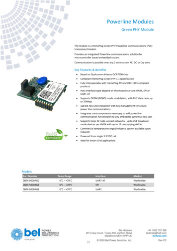
ADA4254Data SheetTIMING SPECIFICATIONSVDDH 28 V, VSSH 28 V, AVDD 5 V, AVSS 0 V, DVDD 3.3 V, DVSS 0 V, VOCM AVDD/2 V.Table 2. Digital Values and SPI Timing SpecificationsParameterMaximum Clock Rate (SCLK)Minimum Pulse Width (SCLK)HighLowSDI/SDO to SCLK Setup TimeSDI/SDO to SCLK Hold TimeData Valid, SDO to SCLKSetup Time, CS to SCLKTest 05030Timing DiagramsINSTRUCTION CYCLEDATA TRANSFER CYCLECSSDIOR/W A6A5A4 A3A2 A1A0 D7N D6 N D5 ND30 D20 D1 0 D00D7 N D6N D5 ND30 D20 D10 D0 0SDO15741-002SCLKFigure 2. SPI Timing Diagram, MSB FirsttDCStSCLKCStPWHtPWLtDSSDItDHINSTRUCTION BIT 7INSTRUCTION BIT 615741-003SCLKFigure 3. SPI Register Write Timing DiagramCStDVSDI,SDODATA BIT nDATA BIT n – 1Figure 4. SPI Register Read Timing DiagramRev. B Page 8 of 5915741-004SCLKTypMax5UnitMHznsnsnsnsnsns
Data SheetADA4254ABSOLUTE MAXIMUM RATINGSTHERMAL RESISTANCETable 3.ParameterVDDHAVDDDVDDAVSS or DVSSVoltageCurrentInput Voltage ( IN1, IN1, IN2,or IN2)Differential Input VoltageBetween Any Two AmplifierInputs ( IN1, IN1, IN2, or IN2) OUT, OUT Short-CircuitCurrentVOCMVoltageCurrentDigital Inputs/Outputs (SPI andGPIO), VoltageDigital Inputs (SPI and GPIO),CurrentIOUT LVVoltageCurrentIOUT HVVoltageCurrentOperating Temperature RangeSpecified Temperature RangeMaximum Junction TemperatureStorage Temperature RangeRatingVSSH – 0.3 V to VSSH 60 VAVSS – 0.3 V to AVSS 5.5 VDVSS – 0.3 V to DVSS 5.5 VVSSH – 0.3 V to VSSH 30 VVDDH – 30 V to VDDH 0.3 V 10 mAVSSH 60 V to VSSH 60 VThermal performance is directly linked to printed circuit board(PCB) design and operating environment. Careful attention toPCB thermal design is required.θJA is the natural convection, junction to ambient, thermalresistance measured in a one cubic foot sealed enclosure. θJCis the junction to case thermal resistance.Table 4. Thermal ResistancePackage Type1CP-28-10RU-2460 V1IndefiniteAVSS – 0.3 V to AVDD 0.3 V 10 mADVSS – 0.3 V to DVDD 0.3 VθJA36.964.8θJC1.914.11Unit C/W C/WThe thermal resistance values specified in Table 4 are simulated based onJEDEC specifications (unless specified otherwise) and must be used incompliance with JESD51-12.Refer to the ESD Map section for a schematic of ESD diodesand paths.ESD CAUTION 10 mAAVSS – 0.3 V to AVDD 0.3 V 10 mAVSSH – 0.3 V to VDDH 0.3 V 10 mA 40 C to 125 C 40 C to 105 C 150 C 65 C to 150 CStresses at or above those listed under Absolute Maximum Ratingsmay cause permanent damage to the product. This is a stress ratingonly; functional operation of the product at these or any otherconditions above those indicated in the operational section of thisspecification is not implied. Operation beyond the maximumoperating conditions for extended periods may affect productreliability.Rev. B Page 9 of 59
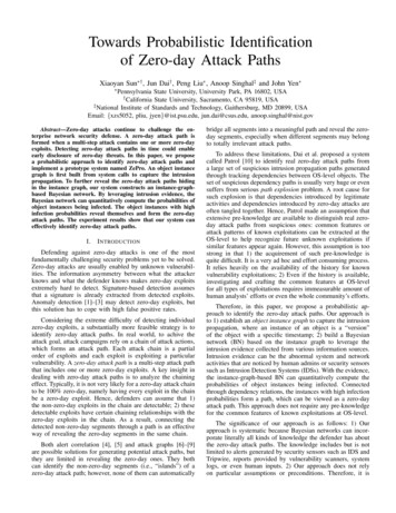
ADA4254Data Sheet21 VOCM IN1 1–IN1 2ADA425418 GPIO017 GPIO1TOP VIEWDNC 5EPADDVSS 6DVDD 716 GPIO2NOTES1. DNC DO NOT CONNECT. DO NOT CONNECTTO THIS PIN.2. CONNECT THE EXPOSED PAD (EPAD)TO VSSH.124 OUT223GPIO0AVSS322GPIO1AVDD421GPIO2IOUT LV520GPIO3IOUT HV619GPIO4VDDH7VSSH8 IN1ADA4254TOP VIEW18CS17SCLK916SDI–IN1 1015SDO IN2 1114DVDD–IN2 1213DVSS15741-006GPIO4 14GPIO5 13GPIO6 12SDOSDI8915 GPIO3CS 11–IN2 4SCLK 10 IN2 320 –OUT19 OUT–OUTVOCM15741-00723 AVDD22 AVSS26 VDDH25 IOUT HV24 IOUT LV28 DNC27 VSSHPIN CONFIGURATIONS AND FUNCTION DESCRIPTIONSFigure 6. 24-Lead TSSOP Pin ConfigurationFigure 5. 28-Lead LFCSP Pin ConfigurationTable 5. Pin Function DescriptionsMnemonic IN1 IN1 IN2 2GPIO1GPIO0 OUT OUTVOCMLFCSP Pin No.12345, 286789101112131415161718192021TSSOP Pin No.9101112Not applicable131415161718Not applicableNot applicable19202122232412AVSSAVDDIOUT LVIOUT HVVDDHVSSHEPAD222324252627345678Not applicableDescriptionChannel 1 Positive Input.Channel 1 Negative Input.Channel 2 Positive Input.Channel 2 Negative Input.Do Not Connect. Do not connect to this pin.Negative Digital Supply Voltage.Positive Digital Supply Voltage.SPI Serial Data Output.SPI Serial Data Input.SPI Serial Clock Input.SPI Chip Select Input.GPIO6/SCS6.GPIO5/SCS5.GPIO4/SCS4/Clock Input or Output.GPIO3/SCS3/Fault Interrupt Output.GPIO2/SCS2/Calibration Busy Out.GPIO1/SCS1/External Multiplexer Control 1.GPIO0/SCS0/External Multiplexer Control 0.Positive Output.Negative Output.Output Amplifier Common-Mode Voltage Input. This pin is high impedanceand is not internally biased.Output Amplifier Negative Supply Voltage.Output Amplifier Positive Supply Voltage.Low Voltage Excitation Current Source Output.High Voltage Excitation Current Source Output.Positive High Voltage Supply.Negative High Voltage Supply.Exposed Pad. Connect the exposed pad (EPAD) to VSSH.Rev. B Page 10 of 59
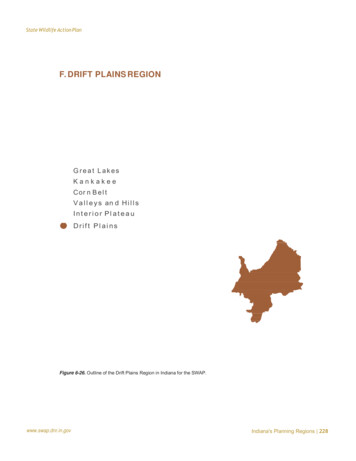
Data SheetADA4254TYPICAL PERFORMANCE CHARACTERISTICSTA 25 C, VDDH 28 V, VSSH 28 V, AVDD 5 V, AVSS 0 V, DVDD 3.3 V, DVSS 0 V, VOCM AVDD/2, and no load,unless otherwise noted.5045PERCENT OF UNITS 0OFFSET VOLTAGE (µV)0504545PERCENT OF UNITS FSET VOLTAGE (µV)015741-126–40N 120 UNITSµ –0.29µV/ Cσ 0.43µV/ CTA –40 C TO 105 C2510–2.0 –1.6 –1.2 –0.8 –0.400.40.81.21.62.0OFFSET VOLTAGE DRIFT (µV/ C)Figure 8. Offset Voltage Distribution, RTI (Gain 1 V/V)Figure 11. Offset Voltage Drift Distribution, RTI (Gain 1 V/V)5050N 120 UNITSµ –0.34mVσ 0.36mV4540PERCENT OF UNITS (%)40353025201530252015105500.40.81.21.62.0OFFSET VOLTAGE (mV)015741-127–2.0 –1.6 –1.2 –0.8 –0.4N 120 UNITSµ –4.84µV/ Cσ 6.9µV/ CTA –40 C TO 105 C35100–1630545–323510–60–4850N 120 UNITSµ –19.2µVσ 22.2µV–100 –80–64Figure 10. Offset Voltage Drift Distribution, RTI (Gain 128 V/V)400–80OFFSET VOLTAGE DRIFT (nV/ C)Figure 7. Offset Voltage Distribution, RTI (Gain 128 V/V)PERCENT OF UNITS (%)30100PERCENT OF UNITS (%)351015741-128PERCENT OF UNITS (%)40N 120 UNITSµ –11.4nV/ Cσ 15.7nV/ CTA –40 C TO 105 C15741-1294515741-131N 120 UNITSµ 0.24µVσ 2.4µV–30–24–18–12–60612182430OFFSET VOLTAGE DRIFT (µV/ C)Figure 12. Offset Voltage Drift Distribution, RTI (Gain 1/16 V/V)Figure 9. Offset Voltage Distribution, RTI (Gain 1/16 V/V)Rev. B Page 11 of 5915741-13050
ADA4254Data Sheet0.150.15N 80 UNITSVOUT (ALL GAINS EXCEPT 1/16V/V) 8V p-pVOUT (1/16V/V) 2V p-p0.10GAIN ERROR (%)0.050–0.050–0.051/41/124811/4 13/8 2GAIN SETTING (V/V)163264 128–0.151/Figure 13. Gain Error vs. Gain Setting0.150.20N 80 UNITSVOUT (ALL GAINS EXCEPT 1/16V/V) 8V p-pVOUT (1/16V/V) 2V p-p0.15GAIN EROR MEAN 3σ (%)0.050–0.05–0.10–0.151/41/21 11/4 13/8 248GAIN SETTING (V/V)163264 1281/1211/4 13/8 248GAIN SETTING (V/V)163264 128N 40 UNITSVOUT (ALL GAINS EXCEPT 1/16V/V) 8V p-pVOUT (1/16V/V) 2V p-p0.100.050–0.05–0.10–0.2015741-0131/116 /81/16 1/81/41/21 11/4 13/8 248GAIN SETTING (V/V)163264 128Figure 17. Gain Error Distribution vs. Gain Setting Using CalibrationCoefficients0.20N 80 UNITSVOUT (ALL GAINS EXCEPT 1/16V/V) 8V p-pVOUT (1/16V/V) 2V p-pTA –40 C TO 105 C0.15GAIN ERROR MEAN 3σ (%)21/4–0.15Figure 14. Gain Error Distribution vs. Gain Setting38Figure 16. Gain Error vs. Gain Setting Using Calibration /81/1615741-015–0.1510–1N 80 UNITSVOUT (ALL GAINS EXCEPT 1/16V/V) 8V p-pVOUT (1/16V/V) 2V p-p0.100.050–0.05–0.10–2–0.2064 TO 12864 128GAIN SETTING CHANGE (V/V)Figure 15. Gain Error Drift vs. Gain SettingFigure 18. Gain Error Deviation Between Sequential Gain SettingsRev. B Page 12 of 5915741-0173232 TO 641616 TO 321 11/4 13/8 248GAIN SETTING (V/V)4 TO 828 TO 161/2 TO 4413/8 TO 21/1 TO 11/4811/4 TO 13/81/1/ TO 12161/ TO 1/421/1/ TO 1/168–315741-016–0.151/ TO 1/84GAIN ERROR MEAN 3σ (%)0.05–0.10–0.10GAIN ERROR DRIFT MEAN 3σ (ppm/ C)GAIN ERROR (%)0.10N 40 UNITSVOUT (ALL GAINS EXCEPT 1/16V/V) 8V p-pVOUT (1/16V/V) 2V p-p
Data Sheet6ADA425410GAIN 1V/VGAIN 1V/V59GAIN NONLINEARITY �2–1012345DIFFERENTIAL OUTPUT VOLTAGE (V)0–4015741-219–68020406080100120TEMPERATURE ( C)Figure 19. Gain Nonlinearity160–2015741-234GAIN NONLINEARITY (ppm)4Figure 22. Gain Nonlinearity vs. Temperature140GAIN 128V/V140120GAIN NCY (Hz)–20145100N 4356 UNITSµ –10.2nV/Vσ 7.9nV/V8010k100k1MN 120 UNITSTA –40 C TO 105 C60CMRR MEAN 3σ (nV/V)353025201540200–20–4010–605–80–65 –55 –45 –35 –25 –15 –55152535CMRR (nV/V)455515741-152PERCENT OF UNITS (%)1kFigure 23. CMRR vs. Frequency with 1 kΩ Imbalance400100FREQUENCY (Hz)Figure 20. CMRR vs. E ( C)Figure 24. CMRR Mean vs. Temperature (Gain 128 V/V)Figure 21. CMRR Distribution (Gain 128 V/V)Rev. B Page 13 of 5915741-2030GAIN 128V/VGAIN 1V/VGAIN 1/16V/V15741-140CMRR (dB)10015741-141CMRR (dB)GAIN 1/16V/V
ADA42545045Data Sheet2.0N 4356 UNITSµ –0.34µV/Vσ 0.13µV/V1.5N 120 UNITSTA –40 C TO 105 CCMRR MEAN 3σ 0.25CMRR (µV/V)45–20–52585105TEMPERATURE ( C)Figure 25. CMRR Distribution (Gain 1 V/V)50–4015741-201PERCENT OF UNITS (%)40Figure 28. CMRR Mean vs. Temperature (Gain 1 V/V)20N 4356 UNITSµ –5.8µV/Vσ 2.1µV/V15N 120 UNITSTA –40 C TO 105 CCMRR MEAN 3σ (µV/V)PERCENT OF UNITS �5–3–11357CMRR (µV/V)15741-151–204550N 4356 UNITSµ 0.3nAσ 0.1nA4585105N 4356 UNITSµ 0.01nAσ 0.14nAPERCENT OF UNITS 0.350.450.550.65INPUT BIAS CURRENT (nA)0.7515741-155PERCENT OF UNITS (%)25–5Figure 29. CMRR Mean vs. Temperature (Gain 1/16 V/V)400–20TEMPERATURE ( C)Figure 26. CMRR Distribution (Gain 1/16 V/V)50–40Figure 27. Input Bias Current Distribution0–0.5–0.3–0.10.10.30.5INPUT OFFSET CURRENT (nA)Figure 30. Input Offset Current DistributionRev. B Page 14 of 590.715741-156015741-202–155
Data SheetADA42541058463INPUT OFFSET CURRENT 80100120TEMPERATURE ( C)–5–4015741-211INPUT OFFSET CURRENT (nA)0–5–10–15–20–24 –20 –16 812162024Figure 35. Input Offset Current vs. Input Common-Mode Voltage20VSSH –15VVDDH 15V15INPUT BIAS CURRENT (µA)1050 15OVPVSSH – 60V–8INPUT COMMON-MODE VOLTAGE (V)20–5VSSH –25VVDDH 25V–10–24 –20 –16 –12Figure 32. Input Bias Current vs. Input Common-Mode VoltageOVPVSSH 60V–15VSSH –5VVDDH 5V1050 5–5OVPVSSH 60VOVPVSSH – 60V–10–15–75–60–45–30 –15015INPUT VOLTAGE (V)30456015741-230INPUT BIAS CURRENT (µA)80–8VSSH –25VVDDH 25VINPUT COMMON-MODE VOLTAGE (V)–20–906085–104010IB IB–101520Figure 34. Input Offset Current vs. Temperature15741-153INPUT BIAS CURRENT (nA)150TEMPERATURE ( C)Figure 31. Input Bias Current vs. N 15 UNITSFigure 33. Input Overvoltage Performance, VDDH/VSSH 15 V–20–75 –65 –55 –45 –35 –25 –15 –55152535455565INPUT VOLTAGE (V)Figure 36. Input Overvoltage Performance, VDDH/VSSH 5 VRev. B Page 15 of 5915741-229INPUT BIAS CURRENT (nA)N 15 UNITS
ADA425430Data SheetGAIN 128V/V2.50GAIN 1V/VFROM VDDHFROM VSSH20INPUT VOLTAGE HEADROOM (V)INPUT COMMON-MODE VOLTAGE (V)2515GAIN 1/4V/V105GAIN 1/8V/V0–5GAIN –4–3–2–10123456DIFFERENTIAL OUTPUT VOLTAGE ERATURE ( C)Figure 37. Diamond Plot15741-157–25Figure 40. Input Voltage Headroom vs. Temperature750700650600550500450–28 –24 –20 –16 –12 –8–40481216202428INPUT COMMON-MODE VOLTAGE (V)650VCM –25V600VCM 25V550500VCM 0V450400–40160140140VDDH PSRR (dB)60GAIN 1/16V/V4080100120GAIN 1V/V100GAIN 1/16V/V80601101001k10kFREQUENCY (Hz)100k1M01101001k10k100kFREQUENCY (Hz)Figure 42. VDDH PSRR vs. FrequencyFigure 39. VSSH PSRR vs. FrequencyRev. B Page 16 of 591M15741-147200–2060402015741-149VSSH PSRR (dB)GAIN 1V/V40GAIN 128V/V120GAIN 128V/V8020Figure 41. Multiplexer On-Resistance vs. Temperature1601000TEMPERATURE ( C)Figure 38. Multiplexer On-Resistance vs. Input Common-Mode Voltage120–2015741-207MULTIPLEXER ON-RESISTANCE (Ω)70015741-208MULTIPLEXER ON-RESISTANCE (Ω)VSSH –28V, VDDH 28VVSSH –5V, VDDH 5V
Data SheetADA4254160160GAIN 128V/VGAIN 128V/V140DVDD PSRR (dB)GAIN 1V/V100GAIN 1/16V/V60120GAIN 1V/V100GAIN 1/16V/V8060404020201101001k10k100k1MFREQUENCY (Hz)0110IAVDDQUIESCENT CURRENT 530354045505560650VSSH –28VVDDH 28V0123456AVVD/DVDD (V)Figure 44. Quiescent Current vs. Supply Voltage (VDDH – VSSH)Figure 47. Quiescent Current vs. Supply Voltage (AVDD/DVDD)100IVSSHIVDDHVNOISE (µV/ Hz)10IAVDDGAIN 1/16V/V1GAIN 1V/V0.10GAIN 128V/VIDVDD–20020406080100TEMPERATURE ( 0AVDD 5VDVDD 3V15741-226QUIESCENT CURRENT (µA)10kFigure 46. DVDD PSRR vs. FrequencyVDDH – VSSH (V)QUIESCENT CURRENT (µA)1kFREQUENCY (Hz)Figure 43. AVDD PSRR vs. 0010015741-2250Figure 45. Quiescent Current vs. Temperature0.010.010.11101001k10kFREQUENCY (Hz)Figure 48. Voltage Noise Spectral Density, RTIRev. B Page 17 of 59100k15741-1258015741-138AVDD PSRR (dB)12015741-204140
ADA4254Data Sheet250250200195nV200100500395nV p-p–50–10010050330nV p-p0–50–1
One Technology Way, P.O. Box 9106, Norwood, MA 02062-9106, U.S.A. . Universal process control front ends Data acquisition systems Test and measurement systems GENERAL DESCRIPTION The ADA4254 is a zero drift, high voltage, low power programmable gain instrumentation amplifier (PGIA) designed for process control and industrial applications. The .