Transcription
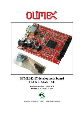
STM32-E407 development boardUSER’S MANUALDocument revision L, October 2021Designed by OLIMEX Ltd, 2012All boards produced by Olimex LTD are ROHS compliant
OLIMEX 2021STM32-E407 user's manualDISCLAIMER 2021 Olimex Ltd. Olimex , logo and combinations thereof, are registered trademarks of Olimex Ltd. Other productnames may be trademarks of others and the rights belong to their respective owners.The information in this document is provided in connection with Olimex products. No license, express orimplied or otherwise, to any intellectual property right is granted by this document or in connection with thesale of Olimex products.This work is licensed under the Creative Commons Attribution-ShareAlike 3.0 Unported License. To view a copy ofthis license, visit .This hardware design by Olimex LTD is licensed under a Creative Commons Attribution-ShareAlike 3.0 UnportedLicense.The software is released under GPL.It is possible that the pictures in this manual differ from the latest revision of the board.The product described in this document is subject to continuous development and improvements. All particulars of theproduct and its use contained in this document are given by OLIMEX in good faith. However all warranties implied orexpressed including but not limited to implied warranties of merchantability or fitness for purpose are excluded. Thisdocument is intended only to assist the reader in the use of the product. OLIMEX Ltd. shall not be liable for any lossor damage arising from the use of any information in this document or any error or omission in such information orany incorrect use of the product.This evaluation board/kit is intended for use for engineering development, demonstration, or evaluation purposes onlyand is not considered by OLIMEX to be a finished end-product fit for general consumer use. Persons handling theproduct must have electronics training and observe good engineering practice standards. As such, the goods beingprovided are not intended to be complete in terms of required design-, marketing-, and/or manufacturing-relatedprotective considerations, including product safety and environmental measures typically found in end products thatincorporate such semiconductor components or circuit boards.Olimex currently deals with a variety of customers for products, and therefore our arrangement with the user is notexclusive. Olimex assumes no liability for applications assistance, customer product design, software performance, orinfringement of patents or services described herein.THERE IS NO WARRANTY FOR THE DESIGN MATERIALS AND THE COMPONENTSUSED TO CREATE STM32-E407. THEY ARE CONSIDERED SUITABLE ONLY FORSTM32-E407.Page 2 of 32
OLIMEX 2021STM32-E407 user's manualTable of ContentsDISCLAIMER. 2CHAPTER 1 OVERVIEW. 51. Introduction to the chapter.51.1 Features.51.2 H407 or E407?.51.3 Target market and purpose of the board.61.4 Organization.6CHAPTER 2 SETTING UP THE STM32-E407 BOARD.72. Introduction to the chapter.72.1 Electrostatic warning.72.2 Requirements. 72.3 Powering the board.82.4 Prebuilt software.8CHAPTER 3 STM32-E407 BOARD DESCRIPTION.93. Introduction to the chapter.93.1 Layout (top view).93.2 Layout (bottom view).9CHAPTER 4 THE STM32F407ZGT6 MICROCONTROLLER. 114. Introduction to the chapter. 114.1 The STM32F407ZGT6 features.11CHAPTER 5 CONTROL CIRCUITY AND HARDWARE MODULES.135. Introduction to the chapter.135.1 Reset.135.2 Clocks.135.3 Power supply circuit. 13CHAPTER 6 CONNECTORS AND PINOUT. 146. Introduction to the chapter.146.1 JTAG/SWD debug. 146.2 SD/MMC slot.146.3 UEXT module.156.4 USB OTG1.166.5 USB OTG2.166.6 LAN connector.176.7 Arduino/Maple platform.176.8 20-pin connectors – PD – PE – PF – PG. 186.9 PWR Jack.196.10 Battery connector.20Page 3 of 32
OLIMEX 2021STM32-E407 user's manual6.11 BOOT pads.206.12 Jumper description.206.12.1 PWR SEL.206.12.2 B1 1/B1 0 and B0 1/B0 0.216.12.3 R-T.216.12.4 3.3V E. 216.12.5 AGND E.216.12.6 AREF EN.216.12.7 GPIO port jumpers.226.13 Additional hardware components. 22CHAPTER 7 HOW TO USE THE BOARD WITH ARDUINO IDE.23CHAPTER 8 BLOCK DIAGRAM AND MEMORY.248. Introduction to the chapter.248.1 Processor family block diagram. 248.2 Physical memory map. 25CHAPTER 9 SCHEMATICS.269. Introduction to the chapter.269.1 Eagle schematic.269.2 Physical dimensions.28CHAPTER 10 REVISION HISTORY AND SUPPORT.2910. Introduction to the chapter.2910.1 Document revision. 2910.2 Hardware revision. 3010.3 Useful web links and purchase codes.3110.4 Product support. 32Page 4 of 32
OLIMEX 2021STM32-E407 user's manualCHAPTER 1 OVERVIEW1. Introduction to the chapterThank you for choosing the STM32-E407 single board computer from Olimex! This documentprovides a user’s guide for the Olimex STM32-E407 board. As an overview, this chapter gives thescope of this document and lists the board’s features. The differences between the members of theSTM32-E407 and STM32-H407 boards are mentioned. The document’s organization is thendetailed.The STM32-E407 development board enables code development of applications running on themicrocontroller STM32F407ZGT6, manufactured by STMicrocontrollers.1.1 Features STM32F407ZGT6 Cortex-M4 210DMIPS, 1MB Flash, 196KB RAM, 3 12-bit 2.4 MSPSA/D, 2 12-bit D/A converters, USB OTG HS and USB OTG HS, Ethernet, 14 timers, 3 SPI,3 I2C, Ethernet, 2 CANs, 3 12 bit ADCs, 2 12 bit DACs, 114 GPIOs, Camera interface JTAG connector with ARM 2x10 pin layout for programming/debugging UEXT connector 2 x USB-OTG SD-card Input DCDC power supply which allows operation from 6-16VDC source Power and User LEDs Reset and User buttons Arduino shield platform with provided headers 4 full 20-pin Ports with the external memory bus for add-on modules PCB: FR-4, 1.5 mm (0,062"), soldermask, silkscreen component print Dimensions: (4.00 x 3.40)” (102 x 86)mm1.2 H407 or E407?The major difference between STM32-H407 and STM32-E407 is that the latter has built-inEthernet (physical level transceiver Microchip's LAN8710A-EZC). STM32-E407 also features anextra USB-OTG and a number of SMD jumpers on the bottom which makes the control of themultiplexing pins easier. STM32-E407 has 2x USB-OTG both with a miniUSB interface. STM32H407 has 1x USB-OTG and 1x USB-HOST with the On-The-Go interfaced by miniUSB and theHOST by USB type A connector.If you need built-in Ethernet check the STM32-E407.Page 5 of 32
OLIMEX 2021STM32-E407 user's manual1.3 Target market and purpose of the boardSTM32-E407 is a development board featuring a powerful ARM Cortex-M4F microcontroller withthe most important peripherals, interfaces and connectors mounted and ready to use. The board canbe powered by a number of different sources, can be programmed via two different interfaces, has aTON of GPIO pins available on a number of headers. The board's Arduino platform headers giveanother option for enthusiasts who wish to implement support for Arduino/Maple/Pinguino shieldsgiving the board additional features altogether with the option to add Olimex extension modules onthe OLIMEX UEXT.The board can be programmed via Arduino IDE using USB OTG1.All of the above options make the board quite versatile and suitable for numerous tasks andsituations. The power of ARM and the creativity of OLIMEX come at the best price and the wellknown quality.Every ARM enthusiast would see STM32-E407 as an interesting bargain and quite capable boardfor its low price.1.4 OrganizationEach section in this document covers a separate topic, organized as follow:– Chapter 1 is an overview of the board usage and features– Chapter 2 provides a guide for quickly setting up the board– Chapter 3 contains the general board diagram and layout– Chapter 4 describes the component that is the heart of the board: the STM32F207ZET6microcontroller– Chapter 5 is an explanation of the control circuitry associated with the microcontroller toreset. Also shows the clocks on the board– Chapter 6 covers the connector pinout, peripherals and jumper description– Chapter 7 gives advice on how to use the board with Arduino IDE– Chapter 8 shows the memory map– Chapter 9 provides the schematics– Chapter 10 contains the revision history, useful links and support informationPage 6 of 32
OLIMEX 2021STM32-E407 user's manualCHAPTER 2 SETTING UP THE STM32-E407 BOARD2. Introduction to the chapterThis section helps you set up the STM32-E407 development board for the first time.Please consider first the electrostatic warning to avoid damaging the board, then discover thehardware and software required to operate the board.The procedure to power up the board is given, and a description of the default board behavior isdetailed.2.1 Electrostatic warningSTM32-E407 is shipped in a protective anti-static package. The board must not be exposed to highelectrostatic potentials. A grounding strap or similar protective device should be worn whenhandling the board. Avoid touching the component pins or any other metallic element.2.2 RequirementsIn order to set up the STM32-E407 optimally, the following items are required:- JTAG or SWD interface programmer/debugger* – can power the board and gives the ability toprogram/debug the board – to choose the correct programmer be sure that you are aware whatsoftware tools you are going to use when programming STM32-E407, and that the programmersupports STM32F407 processor.*The board can also be programmed with Arduino IDE via USB cable with mini USB connectorusing board's USB-OTG1 connector;Additional components can be acquired in order to increase the functionality of the board:- External power supply- USB type “A” to USB type “mini” cable is required for bootlader- SD-card or extension UEXT modules are recommended but not required- 3.7V Battery- MOD-XXXX boards for additional features on the UEXT (RTC, TC, GSM, MP3, RS-485 amongothers) – note that you will have to implement the software setup between the boards- Arduino/Maple/Pinguino shields – every shield is hardware compatible with H407 but will notwork out-of-the-box, software implementation should be consideredSome of the suggested items can be purchased by Olimex, for instance:ARM-USB-TINY-H – high-speed OpenOCD ARM JTAG debuggerARM-USB-OCD-H – high-speed OpenOCD ARM JTAG debugger with buffer protectionUSB-MINI-CABLE – USB mini to USB-A cableBATTERY-LIPO1400MAH – lithium-polymer battery 1400mAhPage 7 of 32
OLIMEX 2021STM32-E407 user's manualUSB-SERIAL-CABLE-F – easy way to connect the board to a computer terminal program usingthe BOOT pinsSY0612E – power supply adapter 12V/0.5A for iMX233-STM32-E4072.3 Powering the boardThe board is powered in one of the following ways: 1) by PWR jack, 2)by JTAG/SWD programmer(3)by USB-OTG.The PWR jack should be supplied from a 6V to 16V source with maximum current of 1A from thepower jack. Without additional components and peripherals (no microSD card mounted, nothingconnected to the USB, etc.) the typical consumption is 30mA @ 12V. For the European customerswe sell an affordable power supply adapter 12V/0.5A – SY0612E.It is worth mentioning that the board can NOT be powered by the battery connector. The batteryconnected keeps some of the processor's functions remain intact during power down but it providesinsufficient power for the board to operate properly. For example the RTC doesn't lose the valueswhen there is a battery connected.2.4 Prebuilt softwareUpon powering initially the board's red PWR LED and the green PWR LED should turn on. Thereare demo examples available for download at the product's page at the Olimex's web-site.Page 8 of 32
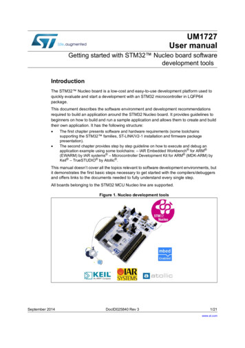
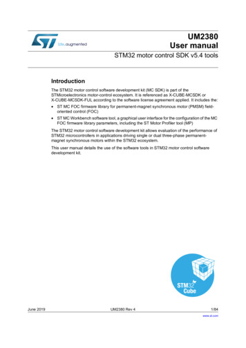
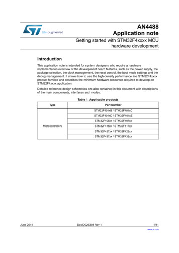
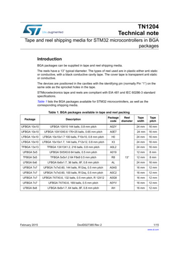
OLIMEX 2021STM32-E407 user's manualCHAPTER 3 STM32-E407 BOARD DESCRIPTION3. Introduction to the chapterHere you get acquainted with the main parts of the board. Note the names used on the board differfrom the names used to describe them. For the actual names check the STM32-E407 board itself.The board comes with a bag with 4 headers for the Arduino/Maple/Pinguino platform which wereleft unsoldered in case you don't wish to use those environments or you don't plan on using shields.There is also a bag of 4 rubber pads which can be placed in the 4 corner holes of the board. Thatway the board will be safe from short-circuiting on the bottom if placed on low-resistance surface.The placement stability of the board will also increase.3.1 Layout (top view)3.2 Layout (bottom view)On the bottom there are three tables printed – general jumper table, boot mode jumper table, powerPage 9 of 32
OLIMEX 2021STM32-E407 user's manualmode jumper table. The default positions of the tables are also shown.Page 10 of 32
OLIMEX 2021STM32-E407 user's manualCHAPTER 4 THE STM32F407ZGT6 MICROCONTROLLER4. Introduction to the chapterIn this chapter is located the information about the heart of STM32-E407 – the Cortex-M4Fmicrocontroller. The information is a modified version of the datasheet provided by itsmanufacturers from ST.4.1 The STM32F407ZGT6 featuresThe processor's features according to the official datasheet: Core: ARM 32-bit Cortex -M4 CPU with FPU, Adaptive real-time accelerator (ARTAccelerator ) allowing 0-wait state execution from Flash memory, frequency up to 168MHz, memory protection unit, 210 DMIPS/1.25 DMIPS/MHz (Dhrystone 2.1), and DSPinstructions Memories 1 Mbyte of Flash memory 192 4 Kbytes of SRAM including 64-Kbyte of CCM (core coupled memory) data RAM Flexible static memory controller supporting Compact Flash, SRAM, PSRAM, NORand NAND memories LCD parallel interface, 8080/6800 modes Clock, reset and supply management 1.8 V to 3.6 V application supply and I/Os POR, PDR, PVD and BOR 4-to-26 MHz crystal oscillator Internal 16 MHz factory-trimmed RC (1% accuracy) 32 kHz oscillator for RTC with calibration Internal 32 kHz RC with calibration Sleep, Stop and Standby modes VBATsupply for RTC, 20 32 bit backup registers optional 4 KB backup SRAM 3 12-bit, 2.4 MSPS A/D converters: 24 channels and 7.2 MSPS in triple interleaved mode 2 12-bit D/A converters General-purpose DMA: 16-stream DMA controller with FIFOs and burst support Up to 17 timers: up to twelve 16-bit and two 32-bit timers up to 168 MHz, each with up to 4IC/OC/PWM or pulse counter and quadrature (incremental) encoder input Debug mode Serial wire debug (SWD) & JTAG interfaces Cortex-M4 Embedded Trace Macrocell 114 I/O ports with interrupt capability Up to 15 communication interfaces 3 I2C interfaces (SMBus/PMBus) 4 USARTs/2 UARTs (10.5 Mbit/s, ISO 7816 interface, LIN, IrDA, modem control) 3 SPIs (37.5 Mbits/s), 2 with muxed full-duplex I2S to achieve audio class accuracy viainternal audio PLL or external clock 2 CAN interfaces (2.0B Active) SDIO interfacePage 11 of 32
OLIMEX 2021STM32-E407 user's manual Advanced connectivity USB 2.0 full-speed device/host/OTG controller with on-chip PHY USB 2.0 high-speed/full-speed device/host/OTG controller with dedicated DMA, onchip full-speed PHY and ULPI 10/100 Ethernet MAC with dedicated DMA: supports IEEE 1588v2 hardware,MII/RMII 8- to 14-bit parallel camera interface up to 54 Mbytes/s True random number generator CRC calculation unit 96-bit unique ID RTC: subsecond accuracy, hardware calendarFor comprehensive information on the microcontroller visit the ST’s web page for a datasheet.At the moment of writing the microcontroller datasheet has a document name DM00037051.pdf andcan be found at the following dfPage 12 of 32
OLIMEX 2021STM32-E407 user's manualCHAPTER 5 CONTROL CIRCUITY AND HARDWAREMODULES5. Introduction to the chapterHere you can find information about reset circuit and quartz crystals locations, the power supplycircuit is discussed.5.1 ResetSTM32-E407's reset circuit includes R5 (10KΩ), R6 (1 KΩ), C19 (100nF) and a RESET button.5.2 ClocksThere are two quartz crystals available on the board:12 MHz quartz crystal Q1 is connected to pins 23 and 24 of the CORTEX-M4F processor.Quartz crystal Q2 is a 32 768Hz RTC (real-time clock) and is connected to pins 8 and 9. The GNDpin of the RTC quartz crystal is not soldered to allow easier change.5.3 Power supply circuitThe power supply circuit of STM32-E407 allows flexible input supply from 6V to 16V directcurrent. This means a wide range of power supplies, adapters, converters are applicable. Themaximum amperage the board can draw is 1A.Note that the Li-Po battery connector cannot be used to fully power the board. Its function is togive an option to save internal data if the board needs to be relocated. It will keep the RTC alive,for instance.If you have successfully powered the board the red PWR LED will turn on. Note that it is possibleto have the PWR LED on even if there isn't enough power for proper operation of the board and allthe peripherals currently connected.Page 13 of 32
OLIMEX 2021STM32-E407 user's manualCHAPTER 6 CONNECTORS AND PINOUT6. Introduction to the chapterIn this chapter are presented the connectors that can be found on the board all together with theirpinout and notes about them. Jumpers functions are described. Notes and info on specificperipherals are presented. Notes regarding the interfaces are given.Note that slashed signals (xxxx/yyyy) in the tables below might mean either multiplexing betweensignals or port name correspondence on the processor.6.1 JTAG/SWD debugThe board can be debugged from the 20-pin JTAG connector either by a JTAG or a SWDcompatible debugger. Below is the table of the JTAG. This interface can be used with the Olimex'sOpenOCD debuggers.JTAG/SWD interfacePin #SignalnameSignalnamePin #1 3.3V11-2 /TRST6GND16GND7PA13/TMS17-8GND18GND9PA14/TCK19 5V JTAG10GND20GND6.2 SD/MMC slotThe microSD card slot is a standard 8pin connector.We have tested a number of microSD cards on the STM32-E407 boards and all of them worked fineregardless manufacturer or capacity. However, keep in mind that some of the lower quality microSDcards might draw too much current from the slot which might cause power-state problems. If yoususpect the microSD card is causing problems please try using another one of better quality forbetter results.Page 14 of 32
OLIMEX 2021STM32-E407 user's manualmicroSD card connectorPin #Signal AT0/RES8DAT1/RESNotice that the pad numeration is written at the bottom of STM32-E407 under the microSD cardconnector.When removing the card, please make sure that you release it from the connector by pushing andNOT by pulling the card directly (this can damage both the connector and the microSD card).6.3 UEXT moduleSTM32-E407 board has UEXT connector and can interface Olimex's UEXT modules.For more information on UEXT please visit: https://www.olimex.com/Products/Modules/UEXT/UEXT connectorPin #Wire NameMicrocontroller port13.3V-2GND-3PC6/USART6 TXPC64PC7/USART6 RXPC75PB8/I2C1 SCLPB86PB9/I2C1 SDAPB97PC2/SPI2 MISOPC28PC3/SPI2 MOSIPC39PB10/SPI2 SCK/UART3 TXPB1010PG10/UEXT CSPG10Page 15 of 32
OLIMEX 2021STM32-E407 user's manual6.4 USB OTG1USB On-The-Go, often abbreviated USB OTG, is a specification that allows USB devices such asdigital audio players or mobile phones to act as a host allowing a USB flash drive, mouse, orkeyboard to be attached and also connecting USB peripherals directly for communication purposesamong them.Note DFU bootloader uses the USB OTG1 port, and a "USB micro-A" cable is required. This is theport used to program the board via Arduino IDE.Note that the USB-OTG ESD protection ICs are not placed by default. However, there are padsprovided for such protection.Pin #Signal Name1 5V OTG1 PWR2USB OTG1 D-3USB OTG1 D 4PA10/OTG1 FS ID5GND6.5 USB OTG2USB On-The-Go, often abbreviated USB OTG, is a specification that allows USB devices such asdigital audio players or mobile phones to act as a host allowing a USB flash drive, mouse, orkeyboard to be attached and also connecting USB peripherals directly for communication purposesamong them.Note that the USB-OTG ESD protection ICs are not placed by default. However, there are padsprovided for such protection.Pin #Signal name1 5V OTG2 PWR2USB OTG2 D-3USB OTG2 D 4PB12/OTG2 HS ID5GNDPage 16 of 32
OLIMEX 2021STM32-E407 user's manual6.6 LAN connectorPin #Signal name1TD 2TD-3RD GreenLink statusLeftYellowActivity status6.7 Arduino/Maple platformThe Arduino/Maple platform connectors (2x6 pin and 2x8 pin plastic headers) are not mounted butare included in the package. The reasons for not mounting the headers on the pin holes are two: firstyou might not need them if you do not wish to experiment with Arduino/Maple software; secondthere are two rows depending on the shield you might want to use the difference between the tworows is the distance between the two digital rows one is made according to the Arduino shieldstandard (e.g. you want to mount the row there if using Arduino certified shield), the other one isadjusted properly at 100mil step (e.g. you want to solder the digital pins here if using properlyadjusted shields).The pinhole names are printed near the actual pinhole on the top of the board.Arduino platform pinholesCON1CON2PinSignal NameProcessor pin#PinSignal NameProcessor ND-A3PF820GNDGND-A4PF921VINVIN-A5PF1022Page 17 of 32
OLIMEX 2021STM32-E407 user's manualArduino platform pinholesCON3CON4PinSignal NameProcessor pin#PinSignal NameProcessor pin#D0PB7/USART1 RX137D8PG1235D1PB6/USART1 326.8 20-pin connectors – PD – PE – PF – PGThe 4 20-pin connectors combine different processor ports and provide very nice GPIO option –you can use them with your breadboarding wires, you can mount headers, you can take measures,etc, etc.Note that all 4 headers come without connectors (unlike the UEXT or the JTAG) and connectorsare not included in the package (unlike the Arduino platform). However they follow the standard100mil step connectors – not hard to find and mount/solder if needed etc.PDPEPin #Signal namePin#Signal namePin#Signal namePin #Signal name1 3.3V11PD81 114PD114PE114PE115PD2/SD PD147PE4/D3*17PE148PD518PD158PE5/D4*18PE159PD619 5V9PE6/D5*19 5V10PD720GND10PE720GNDPage 18 of 32
OLIMEX 2021STM32-E407 user's manualPFPGPin#Signal namePin #Signal namePF8/A3*1 PG10/UEXT CS4PF114PF11/A6*4PG114PG11/TX 9PF6/A1*19 5V9PG619 5V10PF7/A2*20GND10PG7/D6*20GNDPin #Signal namePin # Signal name1 3.3V112GND3Note that all signals marked with asterisk (*) are multiplexed with signals of the Arduino platform.Those signals can be controlled by the provided jumpers. However, the jumpers are soldered bydefault which enables them on the GPIO connector and the Arduino shield at the same time.PG11, PG13, PG14, PG16 and PG17 are multiplexed with the UEXT and the Ethernet. Theirconnection is not controlled by jumpers.6.9 PWR JackThe power jack used is the typical one used by Olimex in most of our products – the DC barrel jackhas 2.0mm inner pin and 6.3mm hole. More information about the exact component might be foundhere: https://www.olimex.com/wiki/PWRJACK.Pin #Signal name1Power input2GNDMore info about the power supply can be found in chapters 2 and 5 of this manual.Page 19
program/debug the board - to choose the correct programmer be sure that you are aware what software tools you are going to use when programming STM32-E407, and that the programmer supports STM32F407 processor. *The board can also be programmed with Arduino IDE via USB cable with mini USB connector using board's USB-OTG1 connector;