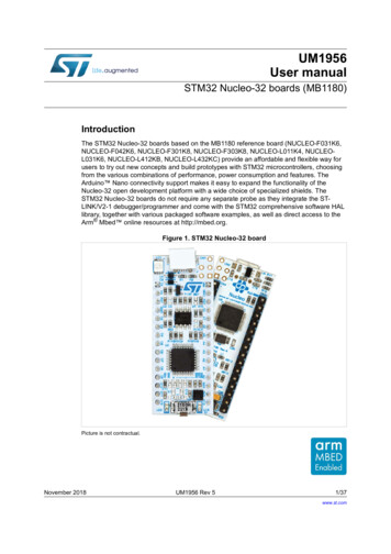
Transcription
UM2380User manualSTM32 motor control SDK v5.4 toolsIntroductionThe STM32 motor control software development kit (MC SDK) is part of theSTMicroelectronics motor-control ecosystem. It is referenced as X-CUBE-MCSDK orX-CUBE-MCSDK-FUL according to the software license agreement applied. It includes the: ST MC FOC firmware library for permanent-magnet synchronous motor (PMSM) fieldoriented control (FOC) ST MC Workbench software tool, a graphical user interface for the configuration of the MCFOC firmware library parameters, including the ST Motor Profiler tool (MP)The STM32 motor control software development kit allows evaluation of the performance ofSTM32 microcontrollers in applications driving single or dual three-phase permanentmagnet synchronous motors within the STM32 ecosystem.This user manual details the use of the software tools in STM32 motor control softwaredevelopment kit.June 2019UM2380 Rev 41/84www.st.com1
ContentsUM2380Contents123General information . . . . . . . . . . . . . . . . . . . . . . . . . . . . . . . . . . . . . . . . . 71.1Definitions . . . . . . . . . . . . . . . . . . . . . . . . . . . . . . . . . . . . . . . . . . . . . . . . . . 71.2Reference documents . . . . . . . . . . . . . . . . . . . . . . . . . . . . . . . . . . . . . . . . 8ST Motor Profiler . . . . . . . . . . . . . . . . . . . . . . . . . . . . . . . . . . . . . . . . . . . . 92.1Launching the ST Motor Profiler . . . . . . . . . . . . . . . . . . . . . . . . . . . . . . . . . 92.2Hardware setup configuration . . . . . . . . . . . . . . . . . . . . . . . . . . . . . . . . . 102.3Hardware setup connection . . . . . . . . . . . . . . . . . . . . . . . . . . . . . . . . . . . 132.4Motor profiling . . . . . . . . . . . . . . . . . . . . . . . . . . . . . . . . . . . . . . . . . . . . . . 162.5Profiled motor saving . . . . . . . . . . . . . . . . . . . . . . . . . . . . . . . . . . . . . . . . 162.6Motor spinning . . . . . . . . . . . . . . . . . . . . . . . . . . . . . . . . . . . . . . . . . . . . . 172.7Closing the ST Motor Profiler . . . . . . . . . . . . . . . . . . . . . . . . . . . . . . . . . . 18The ST Motor Control Workbench . . . . . . . . . . . . . . . . . . . . . . . . . . . . . 193.1Creating a new project . . . . . . . . . . . . . . . . . . . . . . . . . . . . . . . . . . . . . . . 213.2Loading an existing project . . . . . . . . . . . . . . . . . . . . . . . . . . . . . . . . . . . . 233.3Icons and Menu area . . . . . . . . . . . . . . . . . . . . . . . . . . . . . . . . . . . . . . . . 243.42/843.3.1File menu . . . . . . . . . . . . . . . . . . . . . . . . . . . . . . . . . . . . . . . . . . . . . . . . 263.3.2Tools menu . . . . . . . . . . . . . . . . . . . . . . . . . . . . . . . . . . . . . . . . . . . . . . 283.3.3Help menu . . . . . . . . . . . . . . . . . . . . . . . . . . . . . . . . . . . . . . . . . . . . . . . 333.3.4Documentation menu . . . . . . . . . . . . . . . . . . . . . . . . . . . . . . . . . . . . . . . 34Configuring a project . . . . . . . . . . . . . . . . . . . . . . . . . . . . . . . . . . . . . . . . 343.4.1Motor . . . . . . . . . . . . . . . . . . . . . . . . . . . . . . . . . . . . . . . . . . . . . . . . . . . 343.4.2Power stage . . . . . . . . . . . . . . . . . . . . . . . . . . . . . . . . . . . . . . . . . . . . . . 393.4.3Drive management . . . . . . . . . . . . . . . . . . . . . . . . . . . . . . . . . . . . . . . . 503.4.4Control stage . . . . . . . . . . . . . . . . . . . . . . . . . . . . . . . . . . . . . . . . . . . . . 633.5Main hardware settings . . . . . . . . . . . . . . . . . . . . . . . . . . . . . . . . . . . . . . 703.6User information . . . . . . . . . . . . . . . . . . . . . . . . . . . . . . . . . . . . . . . . . . . . 713.7Motor monitoring and spinning . . . . . . . . . . . . . . . . . . . . . . . . . . . . . . . . . 723.7.1Communication link . . . . . . . . . . . . . . . . . . . . . . . . . . . . . . . . . . . . . . . . 733.7.2Motor control dashboard . . . . . . . . . . . . . . . . . . . . . . . . . . . . . . . . . . . . 753.7.3Motor control buttons . . . . . . . . . . . . . . . . . . . . . . . . . . . . . . . . . . . . . . . 793.7.4Status overview . . . . . . . . . . . . . . . . . . . . . . . . . . . . . . . . . . . . . . . . . . . 80UM2380 Rev 4
UM2380Contents4Precautions of use and restrictions . . . . . . . . . . . . . . . . . . . . . . . . . . . 815Revision history . . . . . . . . . . . . . . . . . . . . . . . . . . . . . . . . . . . . . . . . . . . 82UM2380 Rev 43/843
List of tablesUM2380List of tablesTable 1.Table 2.Table 3.Table 4.Table 5.4/84List of acronyms . . . . . . . . . . . . . . . . . . . . . . . . . . . . . . . . . . . . . . . . . . . . . . . . . . . . . . . . . . 7ST Motor Profiler - Troubleshot message examples. . . . . . . . . . . . . . . . . . . . . . . . . . . . . . 14ST MC Workbench – Menu icons . . . . . . . . . . . . . . . . . . . . . . . . . . . . . . . . . . . . . . . . . . . . 25ST MC Workbench - Communication link GUI commands . . . . . . . . . . . . . . . . . . . . . . . . . 73Document revision history . . . . . . . . . . . . . . . . . . . . . . . . . . . . . . . . . . . . . . . . . . . . . . . . . 82UM2380 Rev 4
UM2380List of figuresList of figuresFigure 1.Figure 2.Figure 3.Figure 4.Figure 5.Figure 6.Figure 7.Figure 8.Figure 9.Figure 10.Figure 11.Figure 12.Figure 13.Figure 14.Figure 15.Figure 16.Figure 17.Figure 18.Figure 19.Figure 20.Figure 21.Figure 22.Figure 23.Figure 24.Figure 25.Figure 26.Figure 27.Figure 28.Figure 29.Figure 30.Figure 31.Figure 32.Figure 33.Figure 34.Figure 35.Figure 36.Figure 37.Figure 38.Figure 39.Figure 40.Figure 41.Figure 42.Figure 43.Figure 44.Figure 45.Figure 46.Figure 47.Figure 48.ST Motor Profiler - Icon and location in the start program list. . . . . . . . . . . . . . . . . . . . . . . . 9ST MC Workbench - GUI expanded top view . . . . . . . . . . . . . . . . . . . . . . . . . . . . . . . . . . . . 9ST Motor Profiler - Startup GUI . . . . . . . . . . . . . . . . . . . . . . . . . . . . . . . . . . . . . . . . . . . . . 10ST Motor Profiler - Hardware setup list examples . . . . . . . . . . . . . . . . . . . . . . . . . . . . . . . 11ST Motor Profiler - SM-PMSM parameters example . . . . . . . . . . . . . . . . . . . . . . . . . . . . . 12ST Motor Profiler - I-PMSM parameters example. . . . . . . . . . . . . . . . . . . . . . . . . . . . . . . . 12ST Motor Profiler - Configured GUI . . . . . . . . . . . . . . . . . . . . . . . . . . . . . . . . . . . . . . . . . . 13ST Motor Profiler - Download status window . . . . . . . . . . . . . . . . . . . . . . . . . . . . . . . . . . . 13ST Motor Profiler - Connected GUI. . . . . . . . . . . . . . . . . . . . . . . . . . . . . . . . . . . . . . . . . . . 15ST Motor Profiler - Profiled motor GUI . . . . . . . . . . . . . . . . . . . . . . . . . . . . . . . . . . . . . . . . 16ST Motor Profiler - Save window . . . . . . . . . . . . . . . . . . . . . . . . . . . . . . . . . . . . . . . . . . . . 17ST Motor Profiler - Spin control window (Start). . . . . . . . . . . . . . . . . . . . . . . . . . . . . . . . . . 17ST Motor Profiler - Spin control window (Stop). . . . . . . . . . . . . . . . . . . . . . . . . . . . . . . . . . 18ST Motor Profiler - Tool closure confirmation window . . . . . . . . . . . . . . . . . . . . . . . . . . . . 18ST MC Workbench - Icon and location in the start program list . . . . . . . . . . . . . . . . . . . . . 19ST MC Workbench - GUI (Launch window) . . . . . . . . . . . . . . . . . . . . . . . . . . . . . . . . . . . . 20ST MC Workbench - New Project window . . . . . . . . . . . . . . . . . . . . . . . . . . . . . . . . . . . . . 22ST MC Workbench - New Project Info window . . . . . . . . . . . . . . . . . . . . . . . . . . . . . . . . . . 23ST MC Workbench - Hardware configuration window (global view) . . . . . . . . . . . . . . . . . . 24ST MC Workbench - File menu . . . . . . . . . . . . . . . . . . . . . . . . . . . . . . . . . . . . . . . . . . . . . 26ST MC Workbench - Project saving confirmation window . . . . . . . . . . . . . . . . . . . . . . . . . 27ST MC Workbench - Project Save As window . . . . . . . . . . . . . . . . . . . . . . . . . . . . . . . . . . 27ST MC Workbench - Project Properties window. . . . . . . . . . . . . . . . . . . . . . . . . . . . . . . . . 27ST MC Workbench - Recent project list confirmation window . . . . . . . . . . . . . . . . . . . . . . 28ST MC Workbench - Project deleting confirmation window . . . . . . . . . . . . . . . . . . . . . . . . 28ST MC Workbench - Tools menu . . . . . . . . . . . . . . . . . . . . . . . . . . . . . . . . . . . . . . . . . . . . 28ST MC Workbench - Pin Assignment window . . . . . . . . . . . . . . . . . . . . . . . . . . . . . . . . . . 30ST MC Workbench - Pin Assignment check window . . . . . . . . . . . . . . . . . . . . . . . . . . . . . 30ST MC Workbench - Pin Assignment reset window . . . . . . . . . . . . . . . . . . . . . . . . . . . . . . 30ST MC Workbench - Information window . . . . . . . . . . . . . . . . . . . . . . . . . . . . . . . . . . . . . . 31ST MC Workbench - Script progress window . . . . . . . . . . . . . . . . . . . . . . . . . . . . . . . . . . . 31ST MC Workbench - User information sheet example . . . . . . . . . . . . . . . . . . . . . . . . . . . . 31ST MC Workbench - Monitor window . . . . . . . . . . . . . . . . . . . . . . . . . . . . . . . . . . . . . . . . . 32ST MC Workbench - User information sheet cleared . . . . . . . . . . . . . . . . . . . . . . . . . . . . . 32ST MC Workbench - User information log file example . . . . . . . . . . . . . . . . . . . . . . . . . . . 32ST MC Workbench - Help menu . . . . . . . . . . . . . . . . . . . . . . . . . . . . . . . . . . . . . . . . . . . . . 33ST MC Workbench - About window . . . . . . . . . . . . . . . . . . . . . . . . . . . . . . . . . . . . . . . . . . 33ST MC Workbench - Documentation menu . . . . . . . . . . . . . . . . . . . . . . . . . . . . . . . . . . . . 34ST MC Workbench - Motor window . . . . . . . . . . . . . . . . . . . . . . . . . . . . . . . . . . . . . . . . . . 35ST MC Workbench - Motor parameter GUI (Surface Mounted PMSM) . . . . . . . . . . . . . . . 36ST MC Workbench - Motor parameter GUI (Internal PMSM) . . . . . . . . . . . . . . . . . . . . . . . 37ST MC Workbench - Sensor parameter GUI . . . . . . . . . . . . . . . . . . . . . . . . . . . . . . . . . . . 38ST MC Workbench - Save motor parameter window . . . . . . . . . . . . . . . . . . . . . . . . . . . . . 39ST MC Workbench - Power Stage window. . . . . . . . . . . . . . . . . . . . . . . . . . . . . . . . . . . . . 40ST MC Workbench - AC Input Info GUI . . . . . . . . . . . . . . . . . . . . . . . . . . . . . . . . . . . . . . . 41ST MC Workbench - Rated Bus Voltage Info GUI . . . . . . . . . . . . . . . . . . . . . . . . . . . . . . . 41ST MC Workbench - Bus Voltage Sensing GUI . . . . . . . . . . . . . . . . . . . . . . . . . . . . . . . . . 42ST MC Workbench - Temperature Sensing GUI . . . . . . . . . . . . . . . . . . . . . . . . . . . . . . . . 43UM2380 Rev 45/846
List of figuresFigure 49.Figure 50.Figure 51.Figure 52.Figure 53.Figure 54.Figure 55.Figure 56.Figure 57.Figure 58.Figure 59.Figure 60.Figure 61.Figure 62.Figure 63.Figure 64.Figure 65.Figure 66.Figure 67.Figure 68.Figure 69.Figure 70.Figure 71.Figure 72.Figure 73.Figure 74.Figure 75.Figure 76.Figure 77.Figure 78.Figure 79.Figure 80.Figure 81.Figure 82.Figure 83.Figure 84.Figure 85.Figure 86.Figure 87.Figure 88.Figure 89.Figure 90.Figure 91.Figure 92.6/84UM2380ST MC Workbench - Current Sensing GUI . . . . . . . . . . . . . . . . . . . . . . . . . . . . . . . . . . . . . 44ST MC Workbench - Amplifying Network Gain Calculator GUI . . . . . . . . . . . . . . . . . . . . . 45ST MC Workbench - Over Current Protection GUI . . . . . . . . . . . . . . . . . . . . . . . . . . . . . . . 46ST MC Workbench - Power drivers GUI . . . . . . . . . . . . . . . . . . . . . . . . . . . . . . . . . . . . . . . 47ST MC Workbench - Power Switches GUI . . . . . . . . . . . . . . . . . . . . . . . . . . . . . . . . . . . . . 47ST MC Workbench - Dissipative Brake GUI . . . . . . . . . . . . . . . . . . . . . . . . . . . . . . . . . . . . 48ST MC Workbench - Inrush Current Limiter GUI . . . . . . . . . . . . . . . . . . . . . . . . . . . . . . . . 48ST MC Workbench - Power Factor Correction GUI (Hardware Settings) . . . . . . . . . . . . . . 49ST MC Workbench - Power Factor Correction GUI (PFC Parameters) . . . . . . . . . . . . . . . 50ST MC Workbench - Drive Management window . . . . . . . . . . . . . . . . . . . . . . . . . . . . . . . . 51ST MC Workbench – Speed/Position Feedback Management GUI(Sensor-less using Luenberger observer PLL) . . . . . . . . . . . . . . . . . . . . . . . . . . . . . . . . 52ST MC Workbench – Speed/Position Feedback Management GUI(Sensor-less using Luenberger observer Cordic) . . . . . . . . . . . . . . . . . . . . . . . . . . . . . . 53ST MC Workbench – Speed/Position Feedback Management GUI(Quadrature encoder) . . . . . . . . . . . . . . . . . . . . . . . . . . . . . . . . . . . . . . . . . . . . . . . . . . . . . 54ST MC Workbench – Speed/Position Feedback Management GUI(Hall sensors) . . . . . . . . . . . . . . . . . . . . . . . . . . . . . . . . . . . . . . . . . . . . . . . . . . . . . . . . . . . 55ST MC Workbench – Auxiliary sensor(-less) GUI. . . . . . . . . . . . . . . . . . . . . . . . . . . . . . . . 56ST MC Workbench – Drive Settings GUI . . . . . . . . . . . . . . . . . . . . . . . . . . . . . . . . . . . . . . 57ST MC Workbench – Sensing and Firmware Protection GUI . . . . . . . . . . . . . . . . . . . . . . . 58ST MC Workbench – Start-Up Parameters GUI (Basic Rev-Up) . . . . . . . . . . . . . . . . . . . . 59ST MC Workbench – Start-Up Parameters GUI (Basic On-the-Fly) . . . . . . . . . . . . . . . . . . 60ST MC Workbench – Start-Up Parameters GUI (Advanced Rev-Up). . . . . . . . . . . . . . . . . 61ST MC Workbench – Start-Up Parameters GUI (Advanced On-the-Fly) . . . . . . . . . . . . . . 62ST MC Workbench – Additional Features and PFC settings GUI. . . . . . . . . . . . . . . . . . . . 63ST MC Workbench - FreeRTOS GUI . . . . . . . . . . . . . . . . . . . . . . . . . . . . . . . . . . . . . . . . . 63ST MC Workbench - Control Stage window . . . . . . . . . . . . . . . . . . . . . . . . . . . . . . . . . . . . 64ST MC Workbench – MCU and Clock Frequency GUI . . . . . . . . . . . . . . . . . . . . . . . . . . . . 64ST MC Workbench – Analog Input and Protection GUI (Phase current feedback) . . . . . . 65ST MC Workbench – Analog Input and Protection GUI(Bus voltage feedback) . . . . . . . . . . . . . . . . . . . . . . . . . . . . . . . . . . . . . . . . . . . . . . . . . . . . 66ST MC Workbench – Analog Input and Protection GUI(Temperature feedback) . . . . . . . . . . . . . . . . . . . . . . . . . . . . . . . . . . . . . . . . . . . . . . . . . . . 67ST MC Workbench – Analog Input and Protection GUI(PFC stage feedback) . . . . . . . . . . . . . . . . . . . . . . . . . . . . . . . . . . . . . . . . . . . . . . . . . . . . . 68ST MC Workbench – DAC functionality GUI. . . . . . . . . . . . . . . . . . . . . . . . . . . . . . . . . . . . 69ST MC Workbench – Digital I/O GUI . . . . . . . . . . . . . . . . . . . . . . . . . . . . . . . . . . . . . . . . . 69ST MC Workbench – User Interface Add-on GUI . . . . . . . . . . . . . . . . . . . . . . . . . . . . . . . . 70ST MC Workbench - Main hardware setting area. . . . . . . . . . . . . . . . . . . . . . . . . . . . . . . . 71ST MC Workbench - User information area . . . . . . . . . . . . . . . . . . . . . . . . . . . . . . . . . . . . 71ST MC Workbench - Monitor and spin control GUI. . . . . . . . . . . . . . . . . . . . . . . . . . . . . . . 72ST MC Workbench - Plotting window . . . . . . . . . . . . . . . . . . . . . . . . . . . . . . . . . . . . . . . . . 74ST MC Workbench - Basic dashboard view . . . . . . . . . . . . . . . . . . . . . . . . . . . . . . . . . . . . 75ST MC Workbench - Advanced dashboard view . . . . . . . . . . . . . . . . . . . . . . . . . . . . . . . . 76ST MC Workbench - Expert dashboard register view. . . . . . . . . . . . . . . . . . . . . . . . . . . . . 77ST MC Workbench - Communication link iconsin expert dashboard register view . . . . . . . . . . . . . . . . . . . . . . . . . . . . . . . . . . . . . . . . . . . . 77ST MC Workbench - Import registers configuration window. . . . . . . . . . . . . . . . . . . . . . . . 78ST MC Workbench - Expert dashboard configuration view . . . . . . . . . . . . . . . . . . . . . . . . 78ST MC Workbench - Motor remote control button view . . . . . . . . . . . . . . . . . . . . . . . . . . . 79ST MC Workbench - Motor status view . . . . . . . . . . . . . . . . . . . . . . . . . . . . . . . . . . . . . . . 80UM2380 Rev 4
UM23801General informationGeneral informationThe MC SDK is used for the development of motor-control applications running on STM3232-bit microcontrollers based on Arm (a) Cortex processor(s).The ST MC workbench software tool provides an easy way to configure motor controlapplication software matching hardware setup. The projects generated from this basis arecompatible with the use of STM32CubeMX for further extension or modification of theapplication.ST MC Workbench runs on a Windows 7/10-based PC system equipped with a USBType- A connector for connecting to the application board.Refer to the STM32 MC SDK release note for all information about possible use of the STMC Workbench software tool.Note:ST MC Workbench provides contextual information tips when the cursor goes overparameters in the GUI window.11.1DefinitionsTable 1 lists the acronyms that are relevant for a better understanding of this document.Table 1. List of acronymsAcronymDescriptionGUIGraphical user interfaceIDEIntegrated development environmentFOCField-oriented controlFWFirmwareMCMotor controlMC WBMPMotor control Workbench (STMicroelectronics software tool)Motor Profiler (STMicroelectronics software tool)OCPOver-current protectionPFCPower factor correctionPMSMPermanent-magnet synchronous motorPWMPulse-width modulationSDKSoftware development kita. Arm is a registered trademark of Arm Limited (or its subsidiaries) in the US and/or elsewhere.UM2380 Rev 47/8483
General information1.2UM2380Reference documentsArm documentsThe following documents are available from the http://infocenter.arm.com web page: Cortex -M0 Technical Reference Manual Cortex -M3 Technical Reference Manual Cortex -M4 Technical Reference ManualSTMicroelectronics documentsThe following documents are available from the www.st.com web page:8/84 STM32F0 Series product data sheets STM32F1 Series product data sheets STM32F3 Series product data sheets STM32F4 Series product data sheets STM32F7 Series product data sheets STM32L4 Series product data sheets STM32G0 Series product data sheets STM32G4 Series product data sheets X-NUCLEO-IHM expansion boards FOR motor control - Selection guide on-linepresentationUM2380 Rev 4
UM23802ST Motor ProfilerST Motor ProfilerThe ST Motor Profiler software tool is used to identify the motor’s main PMSMcharacteristics, which are further transferred to the ST MC Workbench.2.1Launching the ST Motor ProfilerLaunch the ST MC Workbench software tool either: by clicking on its icon, or by running it directly from the installation folder treeBoth ways of launching the ST MC Workbench are illustrated in Figure 1.Figure 1. ST Motor Profiler - Icon and location in the start program listOpen the ST Motor Profiler tool either by: using its dedicated button in the ST MC Workbench GUI, as illustrated in Figure 2, or running it directly from the installation folder tree, as illustrated in Figure 1.Figure 2. ST MC Workbench - GUI expanded top viewUM2380 Rev 49/8483
ST Motor ProfilerUM2380A GUI window is displayed by the ST Motor Profiler, as shown in Figure 3.Figure 3. ST Motor Profiler - Startup GUI2.2Hardware setup configurationClick on the Select Boards button (as shown in Figure 3) to display the list of supportedboards, as illustrated in Figure 4. Select the used application board within this list.Note:10/84The ST Motor Profiler tool can be used only with ST hardware in the list of supportedsetups.UM2380 Rev 4
UM2380ST Motor ProfilerFigure 4. ST Motor Profiler - Hardware setup list examplesClick on the STMicroelectronics hardware setup to select it and configure the ST MotorProfiler tool.As an example, Figure 4 shows the selection of the P-NUCLEO-IHM001 motor controlNucleo Pack with NUCLEO-F302R8 and X-NUCLEO-IHM07M1.After hardware setup selection, fill in the parameter fields with the motor information: The number of pole pairs (mandatory field) The Max Speed (optional field)By default, the ST Motor Profiler tool searches for the maximum allowed speedmatching the motor and the hardware setup used. The Max Current allowed by the motor (optional field)By default, it is the maximum peak current deliverable by the hardware setup. The nominal DC bus voltage used by the hardware setup (optional field)By default, it is the power supply stage, either the bus voltage for low voltageapplications (DC voltage), or the RMS value for high voltage applications (AC voltage). The magnetic built-in type (mandatory field)By default, the SM-PMSM is selected. The Ld / Lq ratio (mandatory field) only when I-PMSM built-in is selected (as shown inFigure 6)UM2380 Rev 411/8483
ST Motor ProfilerUM2380Figure 5 gives example values for the BR2804-1700KV-1 motor provided with theP-NUCLEO-IHM001 hardware setup.Figure 5. ST Motor Profiler - SM-PMSM parameters exampleFigure 6. ST Motor Profiler - I-PMSM parameters example12/84UM2380 Rev 4
UM23802.3ST Motor ProfilerHardware setup connectionOnce the ST Motor Profiler is configured, click on the Connect button, as shown in Figure 7.Figure 7. ST Motor Profiler - Configured GUIOnce the connection is requested, a status widows is displayed, as shown in Figure 8. Itscontent depends on the hardware setup history.Figure 8. ST Motor Profiler - Download status windowUM2380 Rev 413/8483
ST Motor ProfilerUM2380If a problem is encountered, a troubleshot message window (among those listed in Table 2)is displayed to support recovery actions.Table 2. ST Motor Profiler - Troubleshot message examplesMessagetypeInformation contentAction neededErrorDepending on the status window:– If the programming procedure cannot beexecuted, check the JTAG/SWDprogramming cable.– If the programming procedure is executedbut the Motor Profiler cannot communicatewith the board, check the serialcommunication connections.WarningWhen the board is new or has been erased,the motor profiler FW is automatically loadedinto the microcontroller by pressing theUpgrade Firmware button to confirm properFW upload.WarningAcknowledge and return to the selection of theboards used in the hardware setup.In case of over- or under-voltage detection,correct the bus voltage setting and its properconnection to the power board.Faults14/84UM2380 Rev 4
UM2380ST Motor ProfilerOnce the connection is successful, the Start Profile button is proposed in the GUI (seeFigure 9).Figure 9. ST Motor Profiler - Connected GUIUM2380 Rev 415/8483
ST Motor Profiler2.4UM2380Motor profilingClick on the Start Profile button proposed in the GUI as indicated in Figure 9 to start motorprofiling.The profiling first identifies the electrical parameters, and then the mechanical ones. In caseof over-current fault detection, the profiling is restarted with a reduced current.When the profiling is successfully completed, all the motor measurements are shown ingreen or orange (depending on their relative accuracy), as illustrated in Figure 10. Whenone or more results are displayed in red, check the hardware setup and restart the motorprofiling sequence.Figure 10. ST Motor Profiler - Profiled motor GUI2.5Profiled motor savingClick on the Save button (refer to Figure 10) to store the motor measurements for later usewith the ST MC Workbench software tool. Figure 11 shows the menu displayed in that case:16/84 Enter the name of the profiled motor, such as BR2804-1700KV-1 Provide details about the profiled motor, such as 3-phase motor with 7 pole-pairs under12 Vdc Eventually add details on the hardware setup usedUM2380 Rev 4
UM2380ST Motor ProfilerFigure 11. ST Motor Profiler - Save window2.6Motor spinningClick on the Play button (refer to Figure 10) to spin the profiled motor.Figure 12 shows the sequence of operations to operate the motor through the spin controlwindow:1.Preset the maximum acceleration2.Click on the Start button to activate motor control3.Adjust the Speed [RPM] slider with the cursorFigure 12. ST Motor Profiler - Spin control window (Start)UM2380 Rev 417/8483
ST Motor ProfilerUM2380Figure 13 shows the two additional steps to stop the motor properly through the spin controlwindow:4.Click on the Stop button to stop activating motor control5.Click on the Done buttonFigure 13. ST Motor Profiler - Spin control window (Stop)2.7Closing the ST Motor ProfilerClick on the Disconnect button (refer to Figure 10) to release the connection properly andclose the ST Motor Profiler window by means of its upper-right icon. A confirmation windowis displayed (see Figure 14).Figure 14. ST Motor Profiler - Tool closure confirmation windowIf the motor parameters have not been saved yet and need to be, proceed as follows:1.Select the No button in the confirmation window2.Click on the Connect button, as shown in Figure 73.Save the motor parameters, as detailed in Section 2.5Clicking on the Yes button closes the ST Motor Profiler software tool, unsaved motorparameters being lost.18/84UM2380 Rev 4
UM23803The ST Motor Control WorkbenchThe ST Motor Control WorkbenchLaunch the ST MC Workbench software tool either by clicking on its icon, or running itdirectly from the installation folder tree, as shown in Figure 15.Figure 15. ST MC Workbench - Icon and location in the start program listThe ST MC Workbench GUI features three different areas (numbered boxes in Figure 16):1.User-buttons: used to start a new project, to load a previous one, or to launch the STMotor Profiler software tool2.Recent Project: used to load a recent project3.Example Projects: used to load a project exampleUM2380 Rev 419/8483
The ST Motor Control WorkbenchUM2380Figure 16. ST MC Workbench - GUI (Launch window)20/84UM2380 Rev 4
UM23803.1The ST Motor Control WorkbenchCreating a new projectClicking on the New Project button (see Figure 16) displays the New Project window (seeFigure 17) used for the definition of the hardware setup information through steps 1 to 4:1.Select the Application Type2.Check the Single Motor or the Dual Motors check box3.Select the ST hardware setup boards:–If the ST board is a complete inverter board (single board with both power andcontrol electronics), select the Inverter combo box and select the Inverter choicefrom the drop-down list–If an ST MC Kit such as P-NUCLEO-IHM001 is used, select the MC Kit combo boxand select the Kit choice from the drop-down list–If the system is composed of a control evaluation board associated with a powerevaluation board, select the Power & Control box and select the Control board andthe Power board from the drop-down lists4.Select the profiled motor from the drop-down list5.Click on the OK button to import all needed hardware settingsUM2380 Rev 421/8483
The ST Motor Control WorkbenchUM2380Figure 17. ST MC Workbench - New Project windowThe created project imports the hardware settings according to the selected boards andmotor profiling results. It also imports other settings like the PWM frequency and the startupacceleration used during motor profiling.22/84UM2380 Rev 4
UM2380The ST Motor Control WorkbenchAfter a few seconds, a New Project Info window is displayed where the motor operatingconditions can be checked, as shown in Figure 18.Figure 18. ST MC Workbench - New Project Info windowClicking on the OK button opens the same GUI (as if loading an existing project), as detailedin Section 3.2.3.2Loading an existing projectClicking on the Load Project button (see Figure 16) displays the hardware configurationwindow used for the tuning of hardware setup information, shown in Figure 19: Icons and Menu: used for the control of all project settings such as project workspacedirectory, used IDE, and others Hardware details setting buttons: used to fine tune the functionalities of the selectedhardware, such as motor parameters or sensor use Main hardware settings: view of the main parameters at a glance User information: feedback about user actions on project settings. As an example, itcan inform the user that a new project has been created, but not yet saved Hardware setup information: informs the user about overall hardware part settingsUM2380 Rev 423/8483
The ST Motor Control WorkbenchUM2380Figure 19. ST MC Workbench - Hardware configuration window (global view)The following sections provide detailed informations about the areas shown in Figure 19:3.3 Section 3.3: Icons and Menu area Section 3.4: Configuring a project Section 3.5: Main hardware settings Section 3.6: User informationIcons and Menu areaThe Icons and Menu area is used for the control of project settings through several menus,described in this section: File menu on page 26 Tools menu on page 28 Help menu on page 33 Documentation menu on page 34Shortcuts exist through usage of icon buttons, as summarized in Table 3.24/84UM2380 Rev 4
UM2380The ST Motor Control WorkbenchTable 3. ST MC Workbench – Menu iconsFunctionIconDescriptionCreate a new projectCreate a new project, as shown in Figure 17Load an existing projectLoad and open an existing project, as shown in Figure 19Save the current projectSave the current project settingsClear the logClear the user information sheet, as shown in Figure 34Pins assignmentCheck the pin assignment of the MCU as well as the pins
ST MC Workbench software tool, a graphical user interface for the configuration of the MC FOC firmware library parameters, including the ST Motor Profiler tool (MP) The STM32 motor control software development kit allows evaluation of the performance of
