Transcription
TN1204Technical noteTape and reel shipping media for STM32 microcontrollers in BGApackagesIntroductionBGA packages can be supplied in tape and reel shipping media.The reels have a 13” typical diameter. The types of reel used are in plastic either anti staticor conductive, with a black conductive cavity tape. The cover tape is transparent anti staticor conductive.The devices are positioned in the cavities with the identifying pin (normally Pin “1”) on thesame side as the sprocket holes in the tape.STMicroelectronics tape and reels are compliant with EIA 481 and IEC 60286-3 standardspecifications.Table 1 lists the BGA packages available for STM32 microcontrollers, as well as thecorresponding shipping media.Table 1. BGA packages available in tape and reel packingTapewidthTapepitchA02Y24 mm16 mmUFBGA 10X10X0.6 176 25 balls, 0.65 mm pitchA0E724 mm16 mmLFBGA 10x10LFBGA 10x10x1.7 100 balls, F10x10, 0.8 mm pitchH024 mm16 mmLFBGA 10x10LFBGA 10x10x1.7, 144 balls, F12x12, 0.8 mm pitchX324 mm16 mmTFBGA 13x13TFBGA 13X13X1.2, 216 balls, 0.8 mm pitchA0L224 mm16 mmUFBGA 5x5UFBGA 5X5X0.6 64 balls, 0.5 mm pitchA01912 mm8 mmTFBGA 5x5TFBGA 5x5x1.2 64 F8x8 0.5 mm pitchR812 mm8 mmLFBGA 6x6LFBGA 6x6x1.7, 36 balls, 6F, 0.8 mm pitchAL24 mm16 mmUFBGA 7x7UFBGA 7x7x0.60, 144 balls, R12sq, 0.5 mm pitchA0AS16 mm12 mmUFBGA 7x7UFBGA 7x7x0.60, 100 balls, R12sq, 0.5 mm pitchA0C216 mm12 mmUFBGA 7x7UFBGA 7X7X0.6, 132 balls, 0.5 mm pitch, R 12X12A0G816 mm12 mmUFBGA 7x7UFBGA 7X7X0.6, 169 balls, 0.5 mm pitchA0YV16 mm12 mmLFBGA 8x8LFBGA 8x8x1.7, 64 balls, 8F, 0.8 mm pitchAH16 mm12 mmPackageDescriptionUFBGA 10x10UFBGA 10X10 144 balls, 0.8 mm pitchUFBGA 10x10February 2015DocID027385 Rev 2PackageReelcodediameter13”1/15www.st.com1
ContentsTN1204Contents1Reel description . . . . . . . . . . . . . . . . . . . . . . . . . . . . . . . . . . . . . . . . . . . . 52Leader and trailer tape specifications . . . . . . . . . . . . . . . . . . . . . . . . . . . 73Labeling . . . . . . . . . . . . . . . . . . . . . . . . . . . . . . . . . . . . . . . . . . . . . . . . . . . 84Device Orientation . . . . . . . . . . . . . . . . . . . . . . . . . . . . . . . . . . . . . . . . . . . 95Carrier tape mechanical dimensions . . . . . . . . . . . . . . . . . . . . . . . . . . . 106Bending radius requirements . . . . . . . . . . . . . . . . . . . . . . . . . . . . . . . . 127Camber requirements . . . . . . . . . . . . . . . . . . . . . . . . . . . . . . . . . . . . . . . 138Revision history . . . . . . . . . . . . . . . . . . . . . . . . . . . . . . . . . . . . . . . . . . . 142/15DocID027385 Rev 2
TN1204List of tablesList of tablesTable 1.Table 2.Table 3.Table 4.Table 5.BGA packages available in tape and reel packing . . . . . . . . . . . . . . . . . . . . . . . . . . . . . . . . 1Reel dimensions . . . . . . . . . . . . . . . . . . . . . . . . . . . . . . . . . . . . . . . . . . . . . . . . . . . . . . . . . . 6Carrier tape constant dimensions . . . . . . . . . . . . . . . . . . . . . . . . . . . . . . . . . . . . . . . . . . . . 10Carrier tape variable dimensions . . . . . . . . . . . . . . . . . . . . . . . . . . . . . . . . . . . . . . . . . . . . 11Document revision history . . . . . . . . . . . . . . . . . . . . . . . . . . . . . . . . . . . . . . . . . . . . . . . . . 14DocID027385 Rev 23/153
List of figuresTN1204List of figuresFigure 1.Figure 2.Figure 3.Figure 4.Figure 5.Figure 6.Figure 7.4/15Reel diagram . . . . . . . . . . . . . . . . . . . . . . . . . . . . . . . . . . . . . . . . . . . . . . . . . . . . . . . . . . . . 5Leader and trailer tape schematics. . . . . . . . . . . . . . . . . . . . . . . . . . . . . . . . . . . . . . . . . . . . 7Labeling location on reel for carrier tape . . . . . . . . . . . . . . . . . . . . . . . . . . . . . . . . . . . . . . . 8Device orientation on tape . . . . . . . . . . . . . . . . . . . . . . . . . . . . . . . . . . . . . . . . . . . . . . . . . . 9Embossed carrier tape . . . . . . . . . . . . . . . . . . . . . . . . . . . . . . . . . . . . . . . . . . . . . . . . . . . . 10Bending radius requirements . . . . . . . . . . . . . . . . . . . . . . . . . . . . . . . . . . . . . . . . . . . . . . . 12Camber requirements . . . . . . . . . . . . . . . . . . . . . . . . . . . . . . . . . . . . . . . . . . . . . . . . . . . . . 13DocID027385 Rev 2
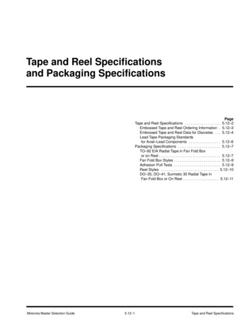
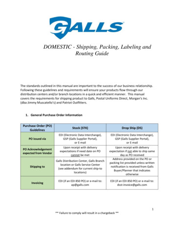
TN12041Reel descriptionReel descriptionFigure 1. Reel diagram)LJXUH 06 9 DocID027385 Rev 25/1514
Reel descriptionTN1204Table 2. Reel dimensions(1)Reeds without drive holeReelsize(inch)Tapesize(mm)Amax.Bmin.(mm)C (mm)(mm)Dmin.(mm)Reeds with drive holeBmin.(mm)Cmax.(mm)Dmin.(mm)N(mm) W1(mm)(2)W2max.(mm)1001212.4 2/-018.416.4 2/-022.424.4 2/-030.4178 513163301.513.0 0.5/0.210020.2NA29.2NA178 5100241781. NA stands for “not applicable”.2. W1 is measured at the hub.6/15DocID027385 Rev 2
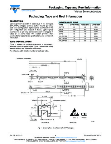
TN12042Leader and trailer tape specificationsLeader and trailer tape specificationsThe leader has a minimum width of 400 mm which includes at least 100 mm of carrier tapewith empty cavities and sealed cover tape (see Figure 2). The leader tape is affixed to thelast turn of carrier tape by using a transparent adhesive anti static or paper based tape of awidth not higher than the one of the cover tape.The trailer is a carrier tape which minimum width is 160 mm with empty cavities and sealedcover tape, as shown in Figure 2. The trailer tape must be affixed to the reel by using thetape slot of the reel hub.During the unwinding operation, the entire carrier tape must be easily released from the reelhub as the last portion of the tape unwinds from the reel without damaging the carrier tapeand the remaining components in the cavities.Figure 2. Leader and trailer tape schematicsDocID027385 Rev 27/1514
Labeling3TN1204LabelingSTMicroelectronics “inner box” standard label is placed on each reel at the followinglocations: On the box that directly holds the reel On the damp proof bag if the units are dry packed On the reel itselfThe label is attached to the flange that is facing the user when the tape is extractedfrom the reel at the top right (see Figure 3).Figure 3. Labeling location on reel for carrier tape8/15DocID027385 Rev 2
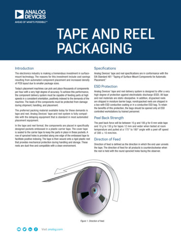
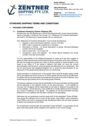
TN12044Device OrientationDevice OrientationThe largest axis of the component outline is perpendicular to the tape length.The device is positioned in the carrier tape cavity as shown in Figure 4: Device orientationon tape. Ball 1 is located on the top left corner of the package.Figure 4. Device orientation on tape86(5 ',5(&7,21 2) )(('06 9 DocID027385 Rev 29/1514
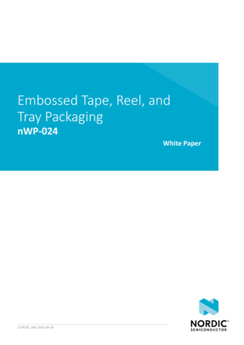
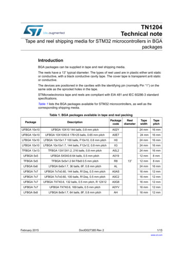
Carrier tape mechanical dimensions5TN1204Carrier tape mechanical dimensionsPossible widths are 12, 16 and 24 mm (refer to Table 1: BGA packages available in tapeand reel packing).Figure 5. Embossed carrier tapeTable 3. Carrier tape constant dimensionsTapewidthD0D1 minE1P012 mm16 mm24 mmP2R(1)S1300.6T max. T1 max.2.0 0.051.5 0.10.01.51.75 0.14.0 0.12.0 0.10.60.11. The maximum radius the tape with or without components can bend without damage is specified in Section 6: Bendingradius requirements).10/15UnitDocID027385 Rev 2mm
TN1204Carrier tape mechanical dimensionsTable 4. Carrier tape variable dimensionsTapewidthB1E2FP1T2 max.W max.12 mm8.210.255.5 0.052.0 0.05 or4.0 0.1 or8.0 0.16.512.316 mm12.114.257.5 0.14.0 0.1 to12.0 0.1 by 4.0increments8.016.324 mm20.122.2511.5 0.14.0 0.1 to20.0 0.1 by 4.0increments12.024.3A0, B0, K0UnitSee (1)mm1. The cavity defined by A0, B0 and K0 surrounds the component with sufficient clearance so that:- The component does not protrude above the top surface of the carrier tape.- The component can be removed vertically from the cavity without mechanical restriction, after the top cover tape hasbeen removed.- Rotation of the component is limited to 20 maximum for 12 mm tapes and to 10 maximum for 16 mm and 24mm tapes.- Lateral movements of the component are restricted to 0.5 mm maximum for 12 mm tapes and to 1.0 mm maximum for16 mm and 24 mm tapes.DocID027385 Rev 211/1514
Bending radius requirements6TN1204Bending radius requirementsFigure 6. Bending radius requirements12/15DocID027385 Rev 2
TN12047Camber requirementsCamber requirementsCarrier camber should not exceed more than 1 mm in 250 mm of carrier tape length.Figure 7. Camber requirementsDocID027385 Rev 213/1514
Revision history8TN1204Revision historyTable 5. Document revision history14/15DateRevisionChanges16-Feb-20151Initial release.19-Feb-20152Updated Figure 1: Reel diagram, Figure 2: Leader andtrailer tape schematics and Figure 5: Embossed carriertape to remove reference to notes.DocID027385 Rev 2
TN1204IMPORTANT NOTICE – PLEASE READ CAREFULLYSTMicroelectronics NV and its subsidiaries (“ST”) reserve the right to make changes, corrections, enhancements, modifications, andimprovements to ST products and/or to this document at any time without notice. Purchasers should obtain the latest relevant information onST products before placing orders. ST products are sold pursuant to ST’s terms and conditions of sale in place at the time of orderacknowledgement.Purchasers are solely responsible for the choice, selection, and use of ST products and ST assumes no liability for application assistance orthe design of Purchasers’ products.No license, express or implied, to any intellectual property right is granted by ST herein.Resale of ST products with provisions different from the information set forth herein shall void any warranty granted by ST for such product.ST and the ST logo are trademarks of ST. All other product or service names are the property of their respective owners.Information in this document supersedes and replaces information previously supplied in any prior versions of this document. 2015 STMicroelectronics – All rights reservedDocID027385 Rev 215/1515
STMicroelectronics tape and reels are compliant with EIA 481 and IEC 60286-3 standard specifications. Table 1 lists the BGA packages available for STM32 microcontrollers, as well as the corresponding shipping media. Table 1. BGA packages available in tape and reel packing Package Description Package code Reel diameter Tape width Tape pitch UFBGA 10x10 UFBGA 10X10 144 balls, 0.8 mm pitch A02Y .