Transcription
UM1727User manualGetting started with STM32 Nucleo board softwaredevelopment toolsIntroductionThe STM32 Nucleo board is a low-cost and easy-to-use development platform used toquickly evaluate and start a development with an STM32 microcontroller in LQFP64package.This document describes the software environment and development recommendationsrequired to build an application around the STM32 Nucleo board. It provides guidelines tobeginners on how to build and run a sample application and allows them to create and buildtheir own application. It has the following structure: The first chapter presents software and hardware requirements (some toolchainssupporting the STM32 families, ST-LINK/V2-1 installation and firmware packagepresentation). The second chapter provides step by step guideline on how to execute and debug anapplication example using some toolchains: – IAR Embedded Workbench for ARM (EWARM) by IAR systems – Microcontroller Development Kit for ARM (MDK-ARM) byKeil – TrueSTUDIO by Atollic .This manual doesn’t cover all the topics relevant to software development environments, butit demonstrates the first basic steps necessary to get started with the compilers/debuggersand offers links to the documents needed to fully understand every single step.All boards belonging to the STM32 MCU Nucleo line are supported.Figure 1. Nucleo development toolsSeptember 2014DocID025840 Rev 31/21www.st.com
ContentsUM1727Contents1System requirements . . . . . . . . . . . . . . . . . . . . . . . . . . . . . . . . . . . . . . . . 52IDEs supporting STM32 Families . . . . . . . . . . . . . . . . . . . . . . . . . . . . . . . 63ST-LINK/V2-1 installation . . . . . . . . . . . . . . . . . . . . . . . . . . . . . . . . . . . . . 74Firmware package . . . . . . . . . . . . . . . . . . . . . . . . . . . . . . . . . . . . . . . . . . . 84.14.252/21Executing and debugging firmware using software toolchains . . . . . . . . . . 84.1.1EWARM toolchain . . . . . . . . . . . . . . . . . . . . . . . . . . . . . . . . . . . . . . . . . . 84.1.2MDK-ARM toolchain . . . . . . . . . . . . . . . . . . . . . . . . . . . . . . . . . . . . . . . 124.1.3TrueSTUDIO toolchain . . . . . . . . . . . . . . . . . . . . . . . . . . . . . . . . . . . . . . 15Software toolchain helpful references and web sites . . . . . . . . . . . . . . . . 19Revision history . . . . . . . . . . . . . . . . . . . . . . . . . . . . . . . . . . . . . . . . . . . 20DocID025840 Rev 3
UM1727List of tablesList of tablesTable 1.Table 2.References and web sites . . . . . . . . . . . . . . . . . . . . . . . . . . . . . . . . . . . . . . . . . . . . . . . . . 19Document revision history . . . . . . . . . . . . . . . . . . . . . . . . . . . . . . . . . . . . . . . . . . . . . . . . . 20DocID025840 Rev 33/213
List of figuresUM1727List of figuresFigure 1.Figure 2.Figure 3.Figure 4.Figure 5.Figure 6.Figure 7.Figure 8.Figure 9.Figure 10.Figure 11.Figure 12.Figure 13.Figure 14.Figure 15.Figure 16.Figure 17.Figure 18.4/21Nucleo development tools . . . . . . . . . . . . . . . . . . . . . . . . . . . . . . . . . . . . . . . . . . . . . . . . . . 1Hardware environment . . . . . . . . . . . . . . . . . . . . . . . . . . . . . . . . . . . . . . . . . . . . . . . . . . . . . 5Package contents . . . . . . . . . . . . . . . . . . . . . . . . . . . . . . . . . . . . . . . . . . . . . . . . . . . . . . . . . 8IAR Embedded Workbench IDE . . . . . . . . . . . . . . . . . . . . . . . . . . . . . . . . . . . . . . . . . . . . . . 9EWARM project successfully compiled. . . . . . . . . . . . . . . . . . . . . . . . . . . . . . . . . . . . . . . . 10Download and Debug button . . . . . . . . . . . . . . . . . . . . . . . . . . . . . . . . . . . . . . . . . . . . . . . 10IAR Embedded Workbench debugger screen . . . . . . . . . . . . . . . . . . . . . . . . . . . . . . . . . . 11Go button . . . . . . . . . . . . . . . . . . . . . . . . . . . . . . . . . . . . . . . . . . . . . . . . . . . . . . . . . . . . . . 11µvision5 IDE . . . . . . . . . . . . . . . . . . . . . . . . . . . . . . . . . . . . . . . . . . . . . . . . . . . . . . . . . . . . 12MDK-ARM project successfully compiled . . . . . . . . . . . . . . . . . . . . . . . . . . . . . . . . . . . . . . 13Start/Stop Debug Session button . . . . . . . . . . . . . . . . . . . . . . . . . . . . . . . . . . . . . . . . . . . . 13MDK-ARM debugger screen. . . . . . . . . . . . . . . . . . . . . . . . . . . . . . . . . . . . . . . . . . . . . . . . 14Run button . . . . . . . . . . . . . . . . . . . . . . . . . . . . . . . . . . . . . . . . . . . . . . . . . . . . . . . . . . . . . 14TrueSTUDIO workspace launcher dialog box . . . . . . . . . . . . . . . . . . . . . . . . . . . . . . . . . . 15Atollic TrueSTUDIO import source select dialog box . . . . . . . . . . . . . . . . . . . . . . . . . . . . 16Atollic TrueSTUDIO import projects dialog box . . . . . . . . . . . . . . . . . . . . . . . . . . . . . . . . 17TrueSTUDIO project successfully compiled. . . . . . . . . . . . . . . . . . . . . . . . . . . . . . . . . . . 17TrueSTUDIO debug window . . . . . . . . . . . . . . . . . . . . . . . . . . . . . . . . . . . . . . . . . . . . . . . . 18DocID025840 Rev 3
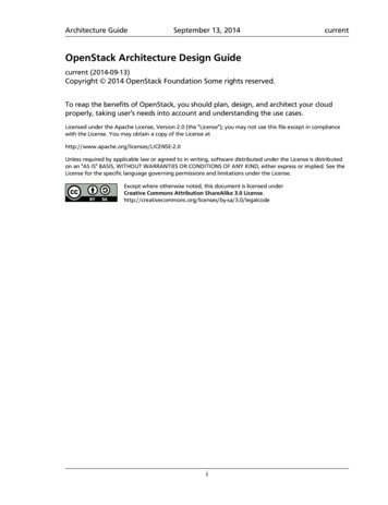
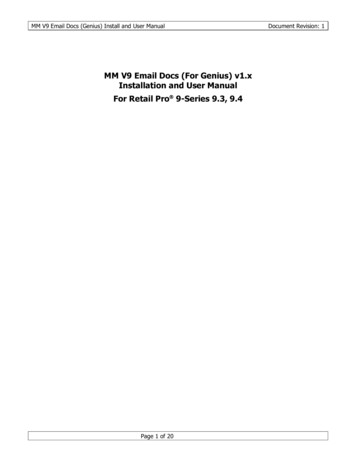
UM17271System requirementsSystem requirementsBefore running your application, you should:1.Install your preferred Integrated Development Environment (IDE).2.ST-LINK/V2-1 driver will be installed automatically. In case of problem, you canproceed with manual installation of the driver from toolchains install directory (furtherdetails are available in Section 3).3.Download the STM32 Nucleo firmware from www.st.com/stm32nucleo.4.Establish the connection with the STM32 Nucleo board by connecting CN1 of theNucleo board to the USB port of the PC.The above steps will be details in the coming sections.Figure 2. Hardware environmentTo run and develop any firmware application on an STM32 Nucleo board, the minimumrequirements are as follows: Windows PC (XP, 7, 8) 'USB type A to Mini-B' cable, used to power the board (through USB connector CN1)from host PC and connect to the embedded ST-LINK/V2-1 for debugging andprogramming.DocID025840 Rev 35/2120
IDEs supporting STM32 Families2UM1727IDEs supporting STM32 FamiliesSTMicroelectronics STM32 families of 32-bit ARM Cortex -M core-based microcontrollersare supported by a complete range of software tools. It encompasses traditional integrateddevelopment environment IDEs with C/C compilers and debuggers from major thirdparties (free versions up to 64KB of code, depending on partner), completed with innovativetools from STMicroelectronics.Toolchains supporting all Nucleo boards are: EWARM v7.10.3 or later(a)–30-day evaluation edition–32 KB Limited QuickStart edition(16KB Limitation for Cortex M0)MDK-ARM v5.01 or later (a)(b)– MDK-Lite (32KB Code size limitation)TrueSTUDIO v5 or later(b)–32 KB Limitation (8KB for Cortex-M0)Information on the toolchain version supporting your STM32 device is available ontoolchain’s release note at partner web site (See Section 4.2).Before installing and using the product, please accept the Evaluation Product LicenseAgreement available at ww.st.com/epla.a. Registration before download is required.b. The device support pack is separate from MDK-ARM releases.6/21DocID025840 Rev 3
UM17273ST-LINK/V2-1 installationST-LINK/V2-1 installationSTM32 Nucleo board includes an ST-LINK/V2-1 embedded debug tool interface. Theinterface needs an ST-LINK/V2-1 dedicated USB driver to be installed. This driver isavailable at ST web site at www.st.com ST-LINK/V2-1 and supported within softwaretoolchains: IAR Embedded Workbench for ARM (EWARM)The toolchain is installed by default in the C:\Program Files\IAR Systems\EmbeddedWorkbench x.x directory on the PC's local hard disk.After installing EWARM, install the ST-LINK/V2-1 driver by running the STLink V2 USB.exe from [IAR INSTALL DIRECTORY]\Embedded Workbenchx.x\arm\drivers\ST-Link \ST-Link V2 USBdriver.exe Keil Microcontroller Development Kit (MDK-ARM) toolchainThe toolchain is installed by default in the C:\Keil directory on the PC's local hard disk;the installer creates a start menu µVision4 shortcut.When connecting the ST-LINK/V2-1 tool, the PC detects new hardware and requires toinstall the ST-LINK V2 USB driver. The “Found New Hardware wizard” appears andguides you through the steps needed to install the driver from the recommendedlocation. Atollic TrueSTUDIO STM32The toolchain is installed by default in the C:\Program Files\Atollic directory on the PC'slocal hard disk.The ST-Link V2 USB.exe file is automatically installed when installing the softwaretoolchain.Complementary information on the firmware package content and the STM32 Nucleorequirements is available on the Getting started with STM32 Firmware.Note:The embedded ST-LINK/V2-1 only supports SWD interface for STM32 devices.DocID025840 Rev 37/2120
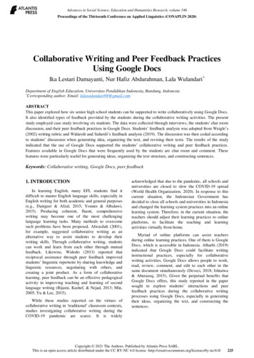
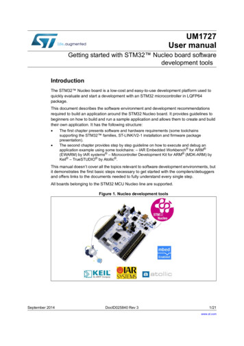
Firmware package4UM1727Firmware packageThe STM32 Nucleo firmware applications, demonstration and IP examples are provided inone single package and supplied in one single zip file. The extraction of the zip filegenerates one folder, STM32 Nucleo FW VX.Y.Z, which contains the following subfolders(see Figure 3).Figure 3. Package contents Template project is a pre-configured project with empty main function to becustomized by the user. This is helpful to start creating your own application based onthe peripherals drivers. Example project includes toolchain projects for each peripheral example ready to berun.4.1Executing and debugging firmware using softwaretoolchains4.1.1EWARM toolchainThe following procedure explains how to compile/link and execute an existing EWARMproject.The steps below can be applied to an already existing example, demonstration or templateproject available from STM32 Nucleo FW VX.Y.Z firmware at www.st.com web site.First of all, you need to go through the firmware/readme.txt file which contains the firmwaredescription and hardware/software requirements.8/21DocID025840 Rev 3
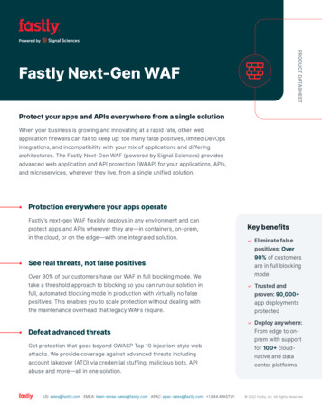
UM1727Firmware package1.Open IAR Embedded Workbench for ARM (EWARM). Figure 4 shows the basicnames of the windows referred to in this document:Figure 4. IAR Embedded Workbench IDE2.In the File menu, select Open and click Workspace to display the Open Workspacedialog box. Browse to select either an example or demonstration or templateworkspace file and click Open to launch it in the Project window.3.In the Project menu, select Rebuild All to compile your project.4.If your project is successfully compiled, Figure 5 is displayed.DocID025840 Rev 39/2120
Firmware packageUM1727Figure 5. EWARM project successfully compiledIf you need to change the project settings (Include and preprocessor defines), gothrough the following project options:–For Include directories:Project Options C/C compiler –For pre-processor defines:Project Options C/C compiler pre-processor 5.In IAR Embedded Workbench IDE, from the Project menu, select Download andDebug or, alternatively, click the Download and Debug button in the toolbar, toprogram the Flash memory and start debugging.Figure 6. Download and Debug button6.10/21The debugger in IAR Embedded Workbench can be used to debug source code at Cand assembly levels, set breakpoints, monitor individual variables and watch eventsduring the code execution.DocID025840 Rev 3
UM1727Firmware packageFigure 7. IAR Embedded Workbench debugger screenTo run your application from the Debug menu, select Go. Alternatively, click the Gobutton in the toolbar to run your application.Figure 8. Go buttonDocID025840 Rev 311/2120
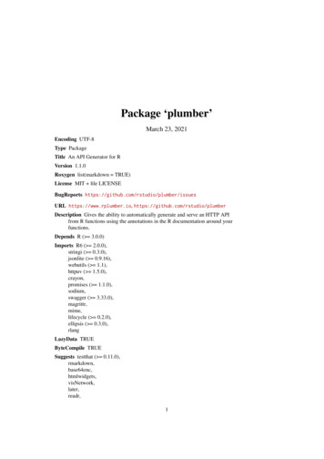
Firmware package4.1.2UM1727MDK-ARM toolchain1.Open Keil MDK-ARM Microcontroller Development Kit. Figure 9 shows the basicnames of the "Keil µvision5" windows referred to in this document.Figure 9. µvision5 IDE12/212.In the Project menu, select Open Project. Browse to select either an example ordemonstration or template project file and click Open to launch it in the Project window.3.In the Project menu, select Rebuild All target files to compile your project.4.If your project is successfully compiled, the following window is displayed:DocID025840 Rev 3
UM1727Firmware packageFigure 10. MDK-ARM project successfully compiledIf you need to change your project settings (Include and preprocessor defines), gothrough the project options:–For Include directories:–For pre-processor defines:Project Options for Target C/C Include PathsProject Options for Target C/C Preprocessor symbols Define5.In MDK-ARM IDE, from the Debug menu, select Start/Stop Debug Session or,alternatively, click the Start/Stop Debug Session button in the toolbar, to program theFlash memory and start debugging.Figure 11. Start/Stop Debug Session button6.The debugger in the MDK-ARM can be used to debug source code at C and assemblylevels, set breakpoints, monitor individual variables and watch events during the codeexecution.DocID025840 Rev 313/2120
Firmware packageUM1727Figure 12. MDK-ARM debugger screenTo run your application from the Debug menu, select Run. Alternatively, click the Runbutton in the toolbar to run your application.Figure 13. Run button14/21DocID025840 Rev 3
UM17274.1.3Firmware packageTrueSTUDIO toolchain1.Open Atollic TrueSTUDIO for ARM product. The program launches and requires theWorkspace location.Figure 14. TrueSTUDIO workspace launcher dialog box2.Browse to select a TrueSTUDIO workspace of either an example or demonstration ortemplate workspace file and click OK to load it.3.To load an existing project in the selected workspace, select Import from the File menuto display the Import dialog box.4.In the Import window, open General, select Existing Projects into Workspace andclick Next.DocID025840 Rev 315/2120
Firmware packageUM1727Figure 15. Atollic TrueSTUDIO import source select dialog box5.16/21Click Select root directory and browse to the TrueSTUDIO workspace folder.DocID025840 Rev 3
UM1727Firmware packageFigure 16. Atollic TrueSTUDIO import projects dialog box6.In the Projects panel, select the project and click Finish.7.In the Project Explorer, select the project, open the Project menu, and click BuildProject.8.If your project is successfully compiled, the following messages will be displayed on theConsole window.Figure 17. TrueSTUDIO project successfully compiledDocID025840 Rev 317/2120
Firmware packageUM1727If you need to change the project settings (Include directories and preprocessordefines), go through Project Properties and select C/C Build Settings from the leftpanel:–For Include directories:–For pre-processor defines:C Compiler Directories Include pathC Compiler Symbols Defined symbols9.To debug and run the application, select the project In the Project Explorer and pressF11 to start a debug session.Figure 18. TrueSTUDIO debug windowThe debugger in the Atollic TrueSTUDIO can be used to debug source code at C andassembly levels, set breakpoints, monitor individual variables and watch events duringthe code execution.To run your application, from the Run menu, select Resume, or alternatively click theResume button in the toolbar.18/21DocID025840 Rev 3
UM17274.2Firmware packageSoftware toolchain helpful references and web sitesTable 1 gives useful references about the integrated development environments describedin this document.Table 1. References and web sitesToolchainWeb www.atollic.comDocID025840 Rev 319/2120
Revision history5UM1727Revision historyTable 2. Document revision history20/21DateRevisionChanges19-May-20141Initial release20-Jun-20142Added new part numbers in the cover page.Removed Table1 Nucleo board General information.09-Sep-20143Replaced all rpns of NUCLEO with reference to the “STM32 MCUNucleo” line.DocID025840 Rev 3
UM1727IMPORTANT NOTICE – PLEASE READ CAREFULLYSTMicroelectronics NV and its subsidiaries (“ST”) reserve the right to make changes, corrections, enhancements, modifications, andimprovements to ST products and/or to this document at any time without notice. Purchasers should obtain the latest relevant information onST products before placing orders. ST products are sold pursuant to ST’s terms and conditions of sale in place at the time of orderacknowledgement.Purchasers are solely responsible for the choice, selection, and use of ST products and ST assumes no liability for application assistance orthe design of Purchasers’ products.No license, express or implied, to any intellectual property right is granted by ST herein.Resale of ST products with provisions different from the information set forth herein shall void any warranty granted by ST for such product.ST and the ST logo are trademarks of ST. All other product or service names are the property of their respective owners.Information in this document supersedes and replaces information previously supplied in any prior versions of this document. 2014 STMicroelectronics – All rights reservedDocID025840 Rev 321/2121
Getting started with STM32 Nucleo board software development tools Introduction The STM32 Nucleo board is a low-cost and easy-to-use development platform used to quickly evaluate and start a development with an STM32 microcontroller in LQFP64 package. This document describes the software environment and development recommendations