Transcription
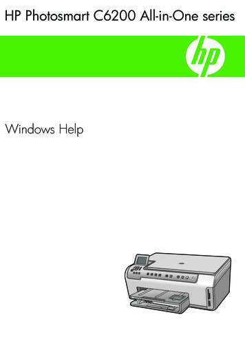
eeeeA 208T & B C A B L E T R AY M E TA L L I C C A B L E T R AY—Channel traySelection guide—01 Solid channel—02 Ventilated channelTo ensure that your channel tray installation willmeet your present and future needs, a sequenceof decisions must be made. These decisions arerelatively simple and can be condensed down tofour steps.—1. Material choice—2. Type of tray bottomBottom type Ventilated SolidCable channel T&B offers cable channel in solid or ventilatedstraight sections. Ventilated channel has burr-free oblong punchedholes for easy access. Ty-Rap cable tie slots are provided betweeneach opening for securing of cable. T&B channel tray meets NEMA VE-1/CSA C22.22.Materials Aluminum Pregalvanized steel Hot-dipped galvanized steel Stainless steel Coatings OtherT&B channel tray systems are fabricatedfrom a corrosion-resistant metal (low-carbonsteel, stainless steel or an aluminum alloy) orfrom a metal with a corrosion-resistant finish(zinc or epoxy). The choice of material for anyparticular installation depends on theinstallation environment (corrosion andelectrical considerations) and cost. Pleaserefer to the technical section (pages A8 to A29)for further explanation.—3. T&B channel tray widthWidths 1.5 in. 3 in. 4 in. 6 in.The width of a channel tray is a function of thenumber, size, spacing and weight of the cablesin the tray. Available nominal widths are 1.5, 3, 4and 6 inches.When specifying width, cable ties or otherspacing devices may be used to maintainthe required air space between cables.—01—02
C H A N N E L T R AYA 209—4. Fittings selection—Straight section number selectionFittings type Horizontal bends (90 , 60 , 45 and 30 ) Horizontal tees and crosses Vertical bends (90 , 60 , 45 and 30 )How to create straight section part numbers1. Select the material2. Select nominal width of tray3. Select the bottom type4. The last number is the length of the channel trayFittings are used to change the size or directionof the channel tray. The most important decisionto be made in fitting design concerns radius.The radius of the bend, whether horizontal orvertical, can be zero (non-radius), 12 in., 24 in. orgreater on a custom basis. The selection requiresa compromise with the considerations beingavailable space, minimum bending radius ofcables, ease of cable pulling and cost.The typical radius is 24 inches.Example:ALTC04V-3 Aluminum 4 in. wide Ventilated bottom 10 ft. lengthBRefer to CSA/NEMA VE2 installation guidelinesfor suggested support locations.Material prefixAluminumPregalvanizedHot-dipped galvanized316 stainless steelALSPSHSSSeriesCable channelT)TCTypeStraight section04CBBFittings are also available for 30 , 45 , 60 and 90 angles. When a standard angle will not work,adjustable elbows can be used. It may be necessaryto add supports to the tray at these points.(ALHV - 3Width (in.)1.501303404606Bottom styleSolid troughVentilated troughSVLength (ft.)103
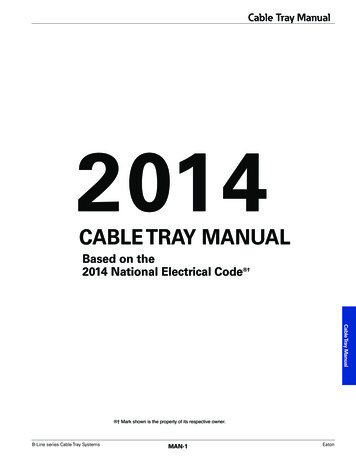
eeT & B C A B L E T R AY M E TA L L I C C A B L E T R AYA 210—Channel tray straight lengthsStraight lengths – Solid and ventilated—01 Bottom view ofventilated channel traylarger than 1.5 in. wideSelection guide Prefix: ALT (alum.), SPT (pregalv.), SHT(hot-dipped galv.), SST (stainless steel) Inside channel widths: 01 1.5 in., 03 3 in.,04 4 in., 06 6 in. Bottom styles: V– ventilated, S– solidee—012.498 in.5.429 in.2.886 in.1.188 in.0.312 in.1.625 in.2.175 in.0.188 in.4 in.0.512 in.9.625 in.2.375 in.—Part numbering systemALMaterialSeriesTCType04WidthV - 3BottomstyleLength
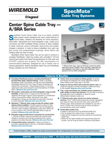
C H A N N E L T R AYA 211H—Channel tray straight lengthsStraight lengths selection guide – Solid and ventilated—01 Vented style offeredin 1.5 in. wide only—02 Vented style offered in3 in., 4 in., 6 in. wide only—03 Solid offeredin all widths—01—02BBB—03
eeT & B C A B L E T R AY M E TA L L I C C A B L E T R AYA 212—Channel tray straight lengthsAluminum straight lengths – Solid and ventilatedWDee Solid: Aluminum – extruded material Ventilated: Pre-punched burr-free oblong holeswith Ty-Rap slots between each opening Accessories: One connector complete withhardware supplied with each length Material: Aluminum-6063-T6Aluminum—Aluminum solid straight lengthsAluminumsolidChannel width(W) (in.)ALTCSupport span (feet)Depth(D) (in.)246810 4Load (lb/ft.)47.511.95.43.01.9 4Deflection (in.)0.1700.6800.7451.3252.0701.531.53313 8Load (lb/ft.)362.590.640.322.717.0313 8Deflection (in.)0.0830.3300.7431.3222.065415 8Load (lb/ft.)580.0145.064.436.324.0415 8Deflection (in.)0.0650.2600.5851.0411.626613 4Load (lb/ft.)607.5151.967.538.025.0613 4Deflection (in.)0.0610.2440.5500.9771.527Channel width(W) (in.)Depth(D) (in.)246—Aluminum ventilated straight lengthsAluminumventilatedALTCSupport span (feet)810 4Load (lb/ft.)47.511.95.43.01.9 4Deflection (in.)0.1700.6800.7451.3252.0701.531.53313 8Load (lb/ft.)300.075.033.318.814.0313 8Deflection (in.)0.1000.4000.9001.6002.500415 8Load (lb/ft.)525.0131.358.332.819.0415 8Deflection (in.)0.0740.2950.6641.1811.846613 4Load (lb/ft.)580.0145.064.436.321.0613 4Deflection (in.)0.0650.2610.5871.0441.631
A 213C H A N N E L T R AYH—Channel tray straight lengthsSteel straight lengths – Solid and ventilatedB Solid: Steel – roll-formed steel Ventilated: Pre-punched burr-free oblong holeswith Ty-Rap slots between each opening Accessories: One connector complete withhardware supplied with each length Material: Pregalvanized, hot-dipped galvanized,316 stainless steelSteelWDB—Steel solid straight lengthsBSteelsolidChannel width(W) (in.)SPTCSHTCSSTC1.531.53Support span (feet)Depth(D) (in.)246810 4Load (lb/ft.)97.524.410.86.13.9 4Deflection (in.)0.0450.1810.4080.7251.133313 8Load (lb/ft.)252.063.028.015.817.0313 8Deflection (in.)0.0340.1340.3020.5380.840415 8Load (lb/ft.)408.0102.045.325.524.0415 8Deflection (in.)0.0260.1050.2370.4210.658613 4Load (lb/ft.)432.0108.048.027.025.0613 4Deflection (in.)0.0240.0960.2170.3860.603Channel width(W) (in.)Depth(D) (in.)246—Steel ventilated straight lengthsSteelventilatedSPTCSHTCSSTCSupport span (feet)810 4Load (lb/ft.)97.524.410.86.13.9 4Deflection (in.)0.0450.1810.4080.7251.1331.531.53313 8Load (lb/ft.)207.051.823.012.914.0313 8Deflection (in.)0.0410.1630.3660.6521.018415 8Load (lb/ft.)363.090.840.322.719.0415 8Deflection (in.)0.0300.1190.2690.4770.746613 4Load (lb/ft.)405.0101.345.025.321.0613 4Deflection (in.)0.0270.1060.2390.4250.664
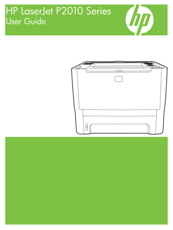
eeeA 214T & B C A B L E T R AY M E TA L L I C C A B L E T R AY—Channel trayFittings—01 Horizontal cross—02 90o Horizontal bende—01—02
C H A N N E L T R AYA 215H—Fittings number selectionBHow to create fitting part numbers1. Select fitting material2. Select nominal width of fitting3. Select type of fitting4. Select degree of angle if required5. Select radiusBExample:ALTF04SHB4512 Aluminum 4 in. wide Horizontal bend 45 degree 12 in. radiusB(ALMaterial prefixAluminumPregalvanizedHot-dipped galvanized316 stainless steelALSPSHSSSeriesCable channelT)TypeFittingTFF04SWidth (in.)1.501303404606Bottom styleSolid troughHB45Fitting typeHorizontal bendHorizontal teeHorizontal crossVertical outside bendVertical inside bendS12HBHTHXVOVIAngle30 45 60 90 30456090Radius (in.)1224Zero radius12240
eeT & B C A B L E T R AY M E TA L L I C C A B L E T R AYA 216—Channel tray fittings90o Horizontal bend fittings—90 o Horizontal bendeeWidthW (in.)Cat. no.*121.5XY(Prefix)-F 01-S-HB90-12153 4153 4161 2123(Prefix)-F 03-S-HB90-12161 2124(Prefix)-F 04-S-HB90-121717126(Prefix)-F 06-S-HB90-121818241.5(Prefix)-F 01-S-HB90-24273 4273 4243(Prefix)-F 03-S-HB90-2428 2281 2244(Prefix)-F 04-S-HB90-242929246(Prefix)-F 06-S-HB90-2430301Z3"XDimensions (in.)RadiusR (in.)R3"ZY*Specify prefixes ALT, SPT, SHT or SSTSelection guide Prefix: ALT (alum.), SPT (pregalv.), SHT(hot-dip galv.), SST (stainless steel) Inside channel widths: 01 1.5 in., 03 3 in.,04 4 in., 06 6 in. Bottom style: S– solid—Part numbering ttingtype24AngleRadius
C H A N N E L T R AYA 217—Channel tray fittings60o Horizontal bend fittingsH—60 o Horizontal bendBDimensions (in.)RadiusR (in.)WidthW (in.)Cat. no.121.5XYZ(Prefix)-F 01-S-HB60-12151 29101 4123(Prefix)-F 03-S-HB60-1216 3 1693 81013 16124(Prefix)-F 04-S-HB60-1216 5 89 5 8111 16126(Prefix)-F 06-S-HB60-12171 2101 81111 16241.5(Prefix)-F 01-S-HB60-242615171 4243(Prefix)-F 03-S-HB60-24926 1615 8173 4244(Prefix)-F 04-S-HB60-242715 818246(Prefix)-F 06-S-HB60-2427 816 818 1635713"ZX3"RZY*Specify prefixes ALT, SPT, SHT or SSTSelection guide Prefix: ALT (alum.), SPT (pregalv.), SHT(hot-dip galv.), SST (stainless steel) Inside channel widths: 01 1.5 in., 03 3 in.,04 4 in., 06 6 in. Bottom style: S– solid—Part numbering ttingtype24AngleRadius9BB
eeT & B C A B L E T R AY M E TA L L I C C A B L E T R AYA 218—Channel tray fittings45o Horizontal bend fittings—45o Horizontal bendee3"Dimensions (in.)RadiusR (in.)WidthW (in.)Cat. no.121.51212XYZ(Prefix)-F 01-S-HB45-12141 857 881 43(Prefix)-F 03-S-HB45-121411 1661 168 9 164(Prefix)-F 04-S-HB45-121561 4813 16126(Prefix)-F 06-S-HB45-12153 461 29 3 16241.5(Prefix)-F 01-S-HB45-2422 89 8131 4243(Prefix)-F 03-S-HB45-2423 89 1613 9 16244(Prefix)-F 04-S-HB45-2423 239 4133 4246(Prefix)-F 06-S-HB45-2424 1610143 16531913ZX3"RZY*Specify prefixes ALT, SPT, SHT or SSTSelection guide Prefix: ALT (alum.), SPT (pregalv.), SHT(hot-dip galv.), SST (stainless steel) Inside channel widths: 01 1.5 in., 03 3 in.,04 4 in., 06 6 in. Bottom style: S– solid—Part numbering ttingtype24AngleRadius
C H A N N E L T R AYA 219—Channel tray fittings30o Horizontal bend fittingsH—30 o Horizontal bendB3"Dimensions (in.)RadiusR (in.)WidthW (in.)Cat. no.121.51212XYZ(Prefix)-F 01-S-HB30-121231 461 23(Prefix)-F 03-S-HB30-12123 835 166 5 84(Prefix)-F 04-S-HB30-12125 83- 3 86 3 4126(Prefix)-F 06-S-HB30-12131 831 27241.5(Prefix)-F 01-S-HB30-24184 49 8243(Prefix)-F 03-S-HB30-24183 8415 16913 16244(Prefix)-F 04-S-HB30-2418 5 85915 16246(Prefix)-F 06-S-HB30-2419 85 810 4311ZXRYZ3"*Specify prefixes ALT, SPT, SHT or SSTSelection guide Prefix: ALT (alum.), SPT (pregalv.), SHT(hot-dip galv.), SST (stainless steel) Inside channel widths: 01 1.5 in., 03 3 in.,04 4 in., 06 6 in. Bottom style: S– solid—Part numbering ttingtype24AngleRadiusB51B
eeT & B C A B L E T R AY M E TA L L I C C A B L E T R AYA 220—Channel tray fittingsHorizontal tee fittings—Horizontal teeeeDimensions (in.)RadiusR (in.)WidthW (in.)Cat. no.121.51212XY(Prefix)-F 01-S-HT-12153 4311 23(Prefix)-F 03-S-HT-12161 2334(Prefix)-F 04-S-HT-121734126(Prefix)-F 06-S-HT-121836241.5(Prefix)-F 01-S-HT-2427 4551 23243(Prefix)-F 03-S-HT-2428 257244(Prefix)-F 04-S-HT-242958246(Prefix)-F 06-S-HT-2430601YW3"RX*Specify prefixes ALT, SPT, SHT or SSTSelection guide Prefix: ALT (alum.), SPT (pregalv.), SHT(hot-dip galv.), SST (stainless steel) Inside channel widths: 01 1.5 in., 03 3 in.,04 4 in., 06 6 in. Bottom style: S– solid—Part numbering ttingtypeRadius
C H A N N E L T R AYA 221—Channel tray fittingsHorizontal cross fittingsH—Horizontal crossBDimensions (in.)RadiusR (in.)WidthW (in.)Cat. no.121.51212XY(Prefix)-F 01-S-HX-12153 4311 23(Prefix)-F 03-S-HX-12161 2334(Prefix)-F 04-S-HX-121734126(Prefix)-F 06-S-HX-121836241.5(Prefix)-F 01-S-HX-2427 4551 23243(Prefix)-F 03-S-HX-2428 257244(Prefix)-F 04-S-HX-242958246(Prefix)-F 06-S-HX-2430601YW3"RX*Specify prefixes ALT, SPT, SHT or SSTSelection guide Prefix: ALT (alum.), SPT (pregalv.), SHT(hot-dip galv.), SST (stainless steel) Inside channel widths: 01 1.5 in., 03 3 in.,04 4 in., 06 6 in. Bottom style: S– solid—Part numbering ttingtypeRadiusBB
eeT & B C A B L E T R AY M E TA L L I C C A B L E T R AYA 222—Channel tray fittings90o Vertical outside/inside bend fittings—90 o Vertical outside bendeeDimensions (in.)RadiusR (in.)WidthW (in.)Cat. no.121.51212XY(Prefix)-F 01-S-VO90-1215153(Prefix)-F 03-S-VO90-1215154(Prefix)-F 04-S-VO90-121515126(Prefix)-F 06-S-VO90-121515241.5(Prefix)-F 01-S-VO90-241515243(Prefix)-F 03-S-VO90-242727244(Prefix)-F 04-S-VO90-242727246(Prefix)-F 06-S-VO90-242727RadiusR (in.)WidthW (in.)Cat. no.*Specify prefixes ALT, SPT, SHT or SST—90 o Vertical inside bendDimensions (in.)XY121.5(Prefix)-F 01-S-VI90-1215 415 4123(Prefix)-F 03-S-VI90-12161 2161 2124(Prefix)-F 04-S-VI90-1216 816 7 8126(Prefix)-F 06-S-VI90-1216 816 7 8241.5(Prefix)-F 01-S-VI90-2427 4273 4243(Prefix)-F 03-S-VI90-24281 2281 2244(Prefix)-F 04-S-VI90-24287 8287 8246(Prefix)-F 06-S-VI90-24287 8287 83773*Specify prefixes ALT, SPT, SHT or SST90 o Outside bend3"ZY3"XSelection guide Prefix: ALT (alum.), SPT (pregalv.), SHT(hot-dip galv.), SST (stainless steel) Inside channel widths: 01 1.5 in., 03 3 in.,04 4 in., 06 6 in. Bottom style: S– solid90 o Inside bendZRRZ3"X3"YZ—Part numbering ttingtype24AngleRadius3
C H A N N E L T R AYA 223—Channel tray fittings60o Vertical outside/inside bend fittingsH—60 o Vertical outside bendBDimensions (in.)RadiusR (in.)WidthW (in.)Cat. no.121.51212XYZ(Prefix)-F 01-S-VO60-12147 88 5 89 7 83(Prefix)-F 03-S-VO60-12147 88 5 89 7 84(Prefix)-F 04-S-VO60-12147 88 5 89 7 8126(Prefix)-F 06-S-VO60-12147 88 5 89 7 8241.5(Prefix)-F 01-S-VO60-2425 414 816 7 8243(Prefix)-F 03-S-VO60-2425 414 816 7 8244(Prefix)-F 04-S-VO60-2425 414 816 7 8246(Prefix)-F 06-S-VO60-2425 414 816 8RadiusR (in.)WidthW (in.)Cat. no.121.512312111155557*Specify prefixes ALT, SPT, SHT or SST—60 o Vertical inside bendDimensions (in.)XYZ(Prefix)-F 01-S-VI60-1215 2910 4(Prefix)-F 03-S-VI60-12161 891 410 3 44(Prefix)-F 04-S-VI60-12161 493 810 7 831126(Prefix)-F 06-S-VI60-1216 89 211241.5(Prefix)-F 01-S-VI60-242615171 4243(Prefix)-F 03-S-VI60-24261 2151 4175 8244(Prefix)-F 04-S-VI60-2426 3 4153 8173 4246(Prefix)-F 06-S-VI60-2426 3 4151 2177 81*Specify prefixes ALT, SPT, SHT or SST60 o Outside bend3"YRZ 3"XRSelection guide Prefix: ALT (alum.), SPT (pregalv.), SHT(hot-dip galv.), SST (stainless steel) Inside channel widths: 01 1.5 in., 03 3 in.,04 4 in., 06 6 in. Bottom style: S– solid60 o Inside bendZ3"XZZY3"—Part numbering ittingtype24AngleRadiusBB
eeT & B C A B L E T R AY M E TA L L I C C A B L E T R AYA 224—Channel tray fittings45o Vertical outside/inside bend fittings—45o Vertical outside bendeeDimensions (in.)RadiusR (in.)WidthW (in.)Cat. no.121.512312XYZ13 85(Prefix)-F 01-S-VO45-12(Prefix)-F 03-S-VO45-125 88135 85 5 848(Prefix)-F 04-S-VO45-12135 85 5 81286(Prefix)-F 06-S-VO45-12135 85 5 82481.5(Prefix)-F 01-S-VO45-24221 891 8127 85243(Prefix)-F 03-S-VO45-24221 891 813244(Prefix)-F 04-S-VO45-24111113246(Prefix)-F 06-S-VO45-24111113*Specify prefixes ALT, SPT, SHT or SST—45o Vertical inside bendDimensions (in.)RadiusR (in.)WidthW (in.)Cat. no.121.512XYZ(Prefix)-F 01-S-VI45-12135 85 5 883(Prefix)-F 03-S-VI45-12135 85 5 88124(Prefix)-F 04-S-VI45-12135 85 5 88126(Prefix)-F 06-S-VI45-12135 85 5 88241.5(Prefix)-F 01-S-VI45-24221 891 8127 8243(Prefix)-F 03-S-VI45-24221 891 813244(Prefix)-F 04-S-VI45-24111113246(Prefix)-F 06-S-VI45-24111113*Specify prefixes ALT, SPT, SHT or SST45o Outside bend3"Selection guide Prefix: ALT (alum.), SPT (pregalv.), SHT(hot-dip galv.), SST (stainless steel) Inside channel widths: 01 1.5 in., 03 3 in.,04 4 in., 06 6 in. Bottom style: S– solid45o Inside bendZYZX3"R3"RXZZY3"—Part numbering ttingtype24AngleRadius
C H A N N E L T R AYA 225—Channel tray fittings30o Vertical outside/inside bend fittingsH—30 o Vertical outside bendBDimensions (in.)RadiusR (in.)WidthW (in.)Cat. no.121.512312XYZ(Prefix)-F 01-S-VO30-1210 871 85 4(Prefix)-F 03-S-VO30-12115 831 861 84(Prefix)-F 04-S-VO30-12115 831 861 8126(Prefix)-F 06-S-VO30-12115 831 861 8241.5(Prefix)-F 01-S-VO30-2417 834 491 2243(Prefix)-F 03-S-VO30-24175 843 491 4244(Prefix)-F 04-S-VO30-24175 843 491 4246(Prefix)-F 06-S-VO30-24175 843 491 4RadiusR (in.)WidthW (in.)Cat. no.121.5(Prefix)-F 01-S-VI30-12123(Prefix)-F 03-S-VI30-12124(Prefix)-F 04-S-VI30-12126(Prefix)-F 06-S-VI30-12241.524151*Specify prefixes ALT, SPT, SHT or SST—30 o Vertical inside bendDimensions (in.)XYZ10 3 817 853 8121 431 26 3 8123 833 85 5 8121 233 85 5 8(Prefix)-F 01-S-VI30-24184 3 49 5 83(Prefix)-F 03-S-VI30-2418 474 893 4244(Prefix)-F 04-S-VI30-2418 84 89 7 8246(Prefix)-F 06-S-VI30-2418 259 7 81371*Specify prefixes ALT, SPT, SHT or SST30 o Outside bend3"Y3"ZXSelection guide Prefix: ALT (alum.), SPT (pregalv.), SHT(hot-dip galv.), SST (stainless steel) Inside channel widths: 01 1.5 in., 03 3 in.,04 4 in., 06 6 in. Bottom style: S– solid30 o Inside bendZRRXZZ3"Y3"—Part numbering ttingtype24AngleRadiusBB
eeA 226T & B C A B L E T R AY M E TA L L I C C A B L E T R AY—Channel tray coversCover selection guide—Tray covers—Cover mountinghardware must beordered separately.eTray covers are available for all widths of tray.They should be installed where falling objectsmay damage cables or where vertical tray runis accessible by pedestrian or vehicular traffic.e—Straight covers These covers provide maximum mechanicalprotection for cables with limited heat build up Flanged covers have 1 2 in. flangeQuantity of standard cover clamps requiredStraight section (10 ft.)6 pcs.NOTE: When using the heavy-duty cover clamps, only half the quantityof pieces are required.—Straight cover number selection(ALMaterial prefixAluminumPregalvanizedHot-dipped galvanized316 stainless steelALSPSHSST)Series prefixCable channelTypeAccessoryi.e.: Straight cover—* Hot-dipped galvanizedcovers only availablein 1500 mm lengths.FT03Width (in.)1.501303404606SFC3Cover styleSolid flanged covers SFCLength (ft.)103
C H A N N E L T R AYA 227H—Fitting covers—Cover mountinghardware must beordered separately.B Fitting covers are available to completeyour cable channel layout All fitting covers are flangedBBQuantity of standard cover clamps requiredHorizontal and vertical bends4 pcs.Tees6 pcs.Crosses8 pcs.Note: When using the heavy-duty cover clamps, only half the quantityof pieces are required.—Fittings cover number selection(ALMaterial prefixAluminumALPregalvanizedSPHot-dipped galvanized SH316 stainless steelSS—*Required for HB,VI and VO only.† Contact yourregional sales officefor availability.T)Series prefixCable channel TTypeFitting coverFF06Width(in.)1.5346 in.01030406HBC45Fitting typeHorizontal bendHorizontal teeHorizontal crossVertical outside bendVertical inside bend12HBCHTCHXCVOCVICAngle*30 3045 4560 6090 90Radius (in.)12122424Zero radius† 0
eA 228T & B C A B L E T R AY M E TA L L I C C A B L E T R AY—Channel tray splice platesStandard and expansion splice plateseSelection guide Prefix: ALT (alum.), SPT (pregalv.), SHT(hot-dip galv.), SST (stainless steel) Inside channel widths: 01 1.5 in., 03 3 in.,04 4 in., 06 6 in.ee—Standard 1.5 in. splice plateCat. no.(Prefix)-W-01-CCSWidth (in.)1.5Supplied standard with each length.Including hardware: 2 bolts, 2 washers, 3 8 in. diameter.—Standard splice plateCat. no.Width W-06-CCS6Supplied standard with each length.Including hardware: 4 bolts, 4 nuts, 4 washers, 3 8 in. diameter.—Expansion splice plateCat. no.Width x)-W-04-ESP4(Prefix)-W-06-ESP6Supplied with hardware for 1.5 in. wide channel: 2 bolts, 2 nuts; all other widths: 4 bolts, 2 stop nuts, 2 serrated flange nuts,4 lock washers (stainless steel ony), 3 8 in. diameter.
A 229C H A N N E L T R AYH—Channel tray splice platesWraparound and adjustable splice platesBSelection guide Prefix: ALT (alum.), SPT (pregalv.), SHT(hot-dip galv.), SST (stainless steel) Inside channel widths: 01 1.5 in., 03 3 in.,04 4 in., 06 6 in.B—Wraparound splice plateBCat. no.Width )-W-04-ACS4(Prefix)-W-06-ACS6Supplied with hardware for 1.5 in. wide channel: 2 bolts, 2 nuts; all other widths: 4 bolts, 4 nuts,4 washers, 3 8 in. diameter.—Adjustable horizontal splice plateCat. no.Width )-W-04-CHA4(Prefix)-W-06-CHA6—Standard vertical adjustable splice plateCat. no.Width )-W-04-CCV4(Prefix)-W-06-CCV6
eA 230T & B C A B L E T R AY M E TA L L I C C A B L E T R AY—Channel tray clamps and hardwareWraparound splice plates and clampseeSelection guide Prefix: ALT (alum.), SPT (pregalv.), SHT(hot-dip galv.), SST (stainless steel) Inside channel widths: 01 1.5 in., 03 3 in.,04 4 in., 06 6 in.—Wraparound vertical adjustable splice plateCat. no.eWidth )-W-04-WAV4(Prefix)-W-06-WAV6—Standard hold-down clampCat. no.Width )-W-04-SHC4(Prefix)-W-06-SHC6—Channel expansion guide clampCat. no.Width )-W-04-CEG4(Prefix)-W-06-CEG6—Combination hold-down/cover clampCat. no.Width )-W-04-CCC4(Prefix)-W-06-CCC6
A 231C H A N N E L T R AYH—Channel tray clamps and hardwareCover clamps, end plates and channel bracketsBSelection guide Prefix: ALT (alum.), SPT (pregalv.), SHT(hot-dip galv.), SST (stainless steel) Inside channel widths: 01 1.5 in., 03 3 in.,04 4 in., 06 6 in.—Heavy-duty cover clampBCat. no.Width )-W-04-HCC4(Prefix)-W-06-HCC6—Closed end plateCat. no.Width )-W-04-CEP4(Prefix)-W-06-CEP6—Channel-mounting bracketCat. no.Width ray plateCat. no.Width )-W-04-CCT4(Prefix)-W-06-CCT6B
eA 232T & B C A B L E T R AY M E TA L L I C C A B L E T R AY—Channel tray brackets and hangersReducer plates, base plates, mounting brackets and hangerseeSelection guide Prefix: ALT (alum.), SPT (pregalv.), SHT(hot-dip galv.), SST (stainless steel) Inside channel widths: 01 1.5 in., 03 3 in.,04 4 in., 06 6 in.—Channel straight reducer plateCat. no.eWidth (in.)(*)-W-03-01-RSP3 to 1(*)-W-04-01-RSP4 to 1(*)-W-06-01-RSP6 to 1(*)-W-04-03-RSP4 to 3(*)-W-06-03-RSP6 to 3(*)-W-06-04-RSP6 to 4—Channel-to-floor base plateCat. no.Width )-W-04-CBP4(Prefix)-W-06-CBP6—Channel-to-tray mounting bracketCat. no.Width )-W-04-TCB4(Prefix)-W-06-TCB6—Single channel hangerCat. no.Designed for use with 1 2 in. threaded rodWidth (in.)SPT-W-06-CCHFor use with all widthsSHT-W-06-CCHFor use with all widthsSST-W-06-CCHFor use with all widths
C H A N N E L T R AYA 233—Channel tray brackets and hangersHangers and channel rubber edge trim Product specifications: Recommendedtemperature range: -40 C through 107 C Recommended temperature range if orderedwith adhesive: -23 C through 70 C Base material: Dense neoprene rubber Very flexible to fit tight radius Wear- and fuel-resistant neoprene Available on request with pre-appliedbutyl sealant or hot-melted adhesive—Double channel hangerCat. no.Width (in.)SPT-W-06-DCHFor use with all widthsSHT-W-06-DCHFor use with all widthsDesigned for use with 1 2 in. threaded rod—Channel rubber edge trimCat. no.RET-BUSH 32 in.91 8 in.3 8 in.WidthDescriptionFor use with 3 in.,4 in. and 6 in.Rubber edge trim – 10 3 4 in. bushing –standard pack of 10RET-50For use with all widthsRubber edge trim – 50 foot rollRET-500For use with all widthsRubber edge trim – 500 foot roll
eT & B C A B L E T R AY M E TA L L I C C A B L E T R AYA 234—Ice and wind loading mapsFigure 250-1USA and 250-2USA loading for grades B, C and DeWIND VELOCITY MAPAnnual extreme wind velocity 30 feet above ground, 50-year recurrence KSMOOKNJWashington oDEDEVAKYAZNMBurnsBurnEurrekaaOHILCOCAMA RICTNYPAIAFresnoUnited StatesSCALSeattleInternational BoundaryLATXFLP CIFICPAOCEANState NameOkklahoma l PasoIndianaianapopolilisSt.Louis Lightf rent loading districts according to theNote: The localities are classified in the diffefferelative simultaneous prevalence of wind velocity and thickness of ice thataccumulates on wires. Light loading is for places where little, if any, iceaccumulates on wires.Little RockAmarilloAbileneAbilenFort WorthDel RioNote: Wind velocity usually increaseswith height; therefore, experience mayshow that the wind pressures specifiedherein need to be further increased. MediumAlaskaKansasCityCiDodge City400 Miles HeavyHawaiiMilfordChicagoDes AlbanyyLansingDetroitDubuqueeDubuquNorth PlatteDennverGrand JunctionnBurlingtonGreennBayMinneapolisRapidapid CityCiCheyenneSalt Lake City400 km0eWinnemucoaTonopahToLasV asVegS. Ste. MarieDuluthhDulutHuronLanderLaCityState nationalF sFallWillistonBismamarrckFargoFaLos AngeleAngelessNational HIDWYGreat FallF mlumbbusW ashingtonBostonHartfordHarNew YoY rkPhiladelphiaPhiladelphiCharleston Ricch ingtonAtlantaAtlantBirminghammJaccksoksonn aksonnvillillePensnsaacolaSan AnAnttonioniooT mpaaTaGULF OF MEXICOA LAL NTICATOCEANMiamamiamBrownsvilleWIND SPEEDSBeloww 70 mph70-80 mph80-90 mph90-100 mphAlaska & Hawaii — 90 mphSpecial WindsSanta Ana Winds — Southern CaliforniaGorge Winds — Columbia River VValley of Washington and OregonWasatch Mountain Winds — UtahChinook Wids — Eastern slope of Rockies in Montana, Wyoming, ColoradoGeneral Loading Map of USAwith respect to loading of overhead lines.Over 100 mphSpecial High WindsOver 100 mphBasic Wind Speed (miles per hour).(This figure is reproduced by permission of the American Society of Civil Engineers.)—01—02NOTE: all maximum wind velocities arein miles per hour based on a 50 yearmean recurrence interval (annualprobability 2%) at a height of 30 ft.(10 m) over smooth terrain.—03—01 General loading mapof USA with respect toloading of overhead lines.—02 Basic wind speed(miles per hour) – USA.—03 General loading mapof Canada with respect toloading of overhead lines.—04 Basic wind speed(miles per hour) – Canada.—04Figure 250-2CDN is a wind map of North Americareproduced from ASCE 7-88 [52]. For Hawaii andPuerto Rico, the basic wind speeds are 80 mphand 95 mph, respectively.Note: Wind velocity usually increases withheight; therefore, experience may show thatthe wind pressures specified herein need tobe further increased.
Ventilated channel has burr-free oblong punched holes for easy access. Ty-Rap cable tie slots are provided between each opening for securing of cable. T&B channel tray meets NEMA VE-1/CSA C22.22. — 3. T&B channel tray width Widths 1.5 in. 3 in. 4 in. 6 in. The width of a channel tray is a function of the