Transcription
DESIGN AND FABRICATION OF THE ASSIGNMENT TRAYMOHD SHAHRIL BIN KHAMISA report submitted in partial fulfillment of the requirementsfor the award of theDiploma of Mechanical EngineeringFaculty of Mechanical EngineeringUniversiti Malaysia PahangNOVEMBER2007
VIABSTRACTNowadays, assignment tray and paper rack was use widespread in wholeworld. Especially as a student, they use assignment tray to store their paper work andassignment sheet. However, there are some things that can't solve by existingassignment tray, for example, can't keep lots of paper, sheet of paper that kept onthat uncovered, sheet of paper scatter in the air, can only kept the paper and notsuitable for writing equipments, and so on. That's why we need the new concept ofthe assignment tray. The main feature of this projects assignment tray was theflexibility to become single stage and double-decker. The idea was appear because ofthe lack functionality in the existing assignment tray in market. The purpose ofdesign this assignment tray was to ensure the documents or assignment sheet is beingkept securely. Drawer was put as the additional feature to get the extra place to keepother items. There are several processes involved during the design and fabricationprocess of this assignment tray. The best feature and shape of assignment tray wasdesigned in order to get the. smart and modern look of product. Several aspectsneeded the full commitment in order to maintain this project run as same as projectplanning and finished on time.
vi'ABSTRAKDewasa kini, bekas helaian tugasan dan rak kertas telah digunakan secarameluas di serata dunia. Terutamanya sebagai seorang pelajar, mereka menggunakanbekas helaian tugasan mi untuk menyimpan kertas kerja dan helaian tugasan-tugasanmereka. Walaubagaimanapun, masih terdapat sesetengah perkara yang tidak dapatditangani oleh bekas helain tugasan yang berada di pasaran sekarang, contohnya,tidak dapat menyimpan helaian kertas dengan kuantiti yang banyak, helaian kertasyang disimpan di dalamnya terdedab, helaian kertas berterbangan di udara, hanyaboleh menyimpan helaian kertas dan tidak sesuai untuk menyimpan peralatanmenulis, dan sebagainya. Kerana itulah kita memerlukan bekas helaian tugasandengan konsep yang baru. Ciri utama pada bekas helaian tugasan di dalam projek miadalah kebolehannya untuk bertukar-tukar menjadi satu tingkat dan dua tingkat.Terhasilnya idea mi adalah daripada kekurangan fungsi yang terdapat pada bekashelaian tugasan yang sedia ada sekarang. Tujuan bekas helaian tugasan mi direkaadalah untuk memastikan keselamatan dokumen dan helaian tugasan yang disimpandi dalamnya sentiasa terjamin. Laci diletakkan sebagai ciii tambahan untükmendapatkan ruang yang lebih untuk menyimpan peralatan-peralatan lain. Terdapatbeberapa langkah yang terlibat sepanjang kerja-kerja mereka dan membuat bekashelaian tugasan ini. Ciri-ciri dan bentuk yang menarik telah direka untukmendapatkan hasil yang baik dan kelihatan moden. Beberapâ aspek perlu diberiperhatian yang sepenuhnya bagi memastikan projek mi berjalan seiring denganrancangan awal dan siap dalam masa yang sepatutnya.
viiiTABLE OF CONTENTSCHAPTERTITLEPAGEFRONT PAGESUPERVISOR'S DECLARATIONiiWRITER TABLE OF CONTENTviiiLIST OF FIGURESxiiLIST OF TABLESxivLIST OF APPENDICESxvINTRODUCTION11.1Project SynopsisI1.2Project Problem Statement11.3Project Scopes21.4Project Objectives21.5Project Planning21.6Project Schedule4
ix2LITERATURE REVIEW52.1Introduction52.2Material - Sheet Metal (Galvanized Iron)62.2.162.32.4Introduction to Sheet Metal2.2.2 Process of Sheet Metal72.2.3ioGalvanizationPunching Process132.3.1Introduction132.3.2Trumatic 2020 Rotation142.3.3Trumatic 2020 Rotation Benefits16Bending Process172.4.117Introduction2.4.2 TRUMPF V85S TRUMABEND Hydraulic2.4.32.5Press Break18Springback in Bending19Welding Process192.5.1Introduction202.5.2Metal Inert Gas Welding (MIG)212.5.3Advantages of PvIIG212.5.4 Disadvantages of MIG222.5.522Spot Welding
KI3METHODOLOGY233.1Project Flow Chart233.2Design and Sketching263.2.1263.34Introduction3.2.2 Design263.2.327Concept Generation3.2.4 Concept Generation and Evaluation333.2.534Design in Solid Work Software3.2.6 Product Design Specification (PDS)35Fabrication Process363.3.136Introduction3.3.2 Process Involved363.3337Step by Step ProcessRESULTS AND DISCUSSION404.1Introduction404.2Overall View of the Design404.2.1Design in Solid Work Software414.2.2 Design in AutoCAD Software42Result434.34.3.1Converting Process434.3.2 Punching Process444.3.3 Bending Process444.3.4 Welding Process454.3.546Assembling Process4.3.6 Painting Process464.4Finished Product474.5Discussion494.5.1Problem Occurs494.5.2Product Specification50
xiCONCLUSION AND RECOMMENDATION515.1 Conclusion515.2 Recommendation52REFERENCES53APPENDICES54
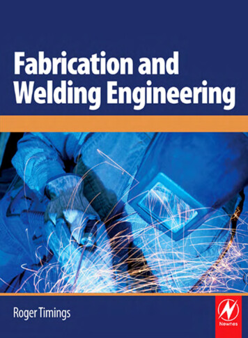
xiiLIST OF FIGURESFIGURE NO.TITLEPAGE2.1Sheet metal62.2Galvanized iron sheet metal102.3Zink coating (Galvanization)122.4Punching process132.5CNC TRUMATIC 2020 rotation FMC compact142.6Bending process172.7Truma Bend V85S182.8Springback in bending192.9Welding process193.1Project flow chart253.2Datum concept27
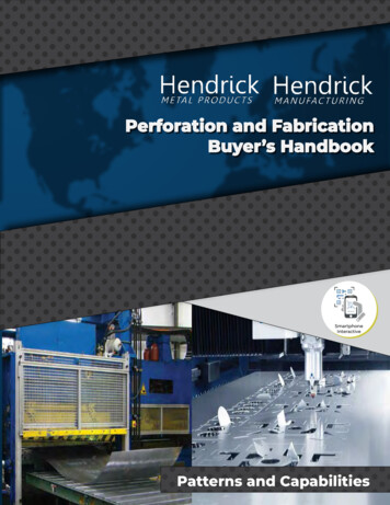
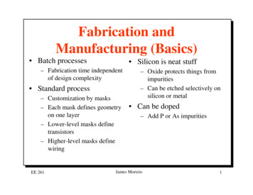
XII'3.3Drawer concept283.4Chest concept293.5Lot of slots concept303.6Rack concept313.7Double-decker concept323.8SolidWork drawing344.1Example of part in SolidWork software414.2Example of part in AutoCAD software424.3Converting process434.4Punching process444.5Bending process454.6Welding process454.7Assembling process464.8Painting process464.9Finished product (in open condition)474.10Finished product (in close condition)48
xivLIST OF TABLESTABLE NO.TITLE1.1Gantt chart for project schedule43.1Concept generation and evaluation334.1Product specification50PAGE
LIST OF APPENDICESAPPENDIXTITLEPAGEATechnical Data of Punching Machine54BTechnical Data of Bending Machine56CSolidWork Drawing Part by part59
CHAPTER 1INTRODUCTION1.1Project SynopsisThis project title is Design and Fabrication of the Assignment Tray. Theproject's prerequisites are types of material, strength of material, skills of design aproduct, skills of using CNC machine and cost of fabricate a product. With the newlydesigned and fabricated assignment tray, simple tests (which is load with someweight was placed on this product) are required to be conducted to verify the design.Overall, this project will acquire the skills of design, analysis, fabrication and testing.1.2Project Problem StatementAs a student, an assignment tray is needed to keep their assignment safely.However, there are some things that can't solve by existing assignment tray. Forexample, there is a limited function of existing assignment tray, such as can't storethe writing equipments. Existing assignment tray also has been defined to be difficultin taking out the assignment sheet from it. Another problem is cover not provided inexisting assignment tray that might flow away the paper.
2Project Scope1.3The scope of the project is limited to the below parameter and material:i.Material- Galvanized Iron (Sheet Metal 1.5mm thickness)ii.Sketching and Drawing- Solid Work software- AutoCAD softwareiii.Fabrication- CNC Turret Punch Machine- Bending Machine- MIG Welding1.4Project Objectivei.To design a new concept of assignment tray which will ensure thedocument is being kept securely.ii.To produce an assignment tray with expandable cover on the top ofthe part.iii.To design and invent an assignment tray with more space for otheritems to be placed.1.5Project PlanningThis project started with made a research and literature review via internet,books, supervisor, and others relevant academic material related to the project title,
3this literature review takes about a week. The reviews not stop there. It continuesalong the way of this project because knowledge is so many to learn.At the same week I do some schedule management for this project whichincluded schedule management. This is done using Microsoft Office Word usingGantt chart system. This also takes a week to accomplish.Also in the same week, this project was started to sketch the hand freedrawing for the project design. At the beginning, 6 concept of design were sketchedfor this project, and from this 6 concept, the best one was chosen to be fabricated.After the design that wants to fabricate was chosen, drawing process using AutoCADand SolidWork software were started.The next task is preparation of mid-presentation and progress report writing,both of these tasks takes one more week to be done. After that, comes the midpresentation week and progress report submission. On this particular weekcommitment was more on the speech preparation for the presentation and doublechecked the report that has to be submitted.The next week, drawing from AutoCAD format was converted into ToPs 300format, software that used in Turret Punch Machine. By using this software,programming code was generated from the origin drawing. This code was saved in(* .lst) format and then read by Computer Numerical Control (CNC) Turret PunchMachine. After the process done, this project was reaching the fabrication process.The fabrication process involved in this project was punching process using turretpunch machine, bending process using banding machine, joining process using MIGwelding.Next task is the final report writing and final presentation preparation. Thistake about one week to accomplished. The report is guided by UMP Thesis writingguided and also the guidance of my supervisor. All the task is scheduled to takeabout fourteen weeks overall.
1.6Project ScheduleTable 1.1: Gantt chart for project 12.Literature Review.Design, Sketching.MeasurementDraw use Solid Work &AutoCADConvert drawing intoC1'TC Format. .Material Preparation.Mid — t WritingFinal Check Report &SubmitFinal Presentation. . .WiiW14
CHAPTER 2LITERATURE REVIEWIntroduction2.1A tray is a shallow platform designed for carrying things. It is larger than asalver, a diminutive version commonly used for lighter and smaller servings, and itcan be fashioned from numerous materials, including silver, brass, sheet iron, wood,and melamine. Some examples have raised galleries, handles, and short feet forsupport.Trays are flat, but with raised edges to stop things from sliding off of them.They are made in a range of shapes but are commonly found in oval or rectangularforms, sometimes with cutout or attached handles with which to carry them.This project was given title 'Design and Fabrication of the Assignment Tray'.This project involve designing and fabricating an assignment box that entirelydifferent from existing assignment box in market. Basically, this project will have 4stages:i.Article review, researching and gathering informationii.Design, sketching by hand, and draw using computer softwareiii.Produce the selected product, using machining processiv.Writing the project report (Thesis)
2.2Material - Sheet Metal (Galvanized Iron)Figure 2.1: Sheet metal2.2.1 Introduction to Sheet MetalSheet Metal is simply metal formed into thin and flat pieces. It is one of thefundamental forms used in metalworking, and can be cut and bend into a variety ofdifferent shapes. Thicknesses can vary significantly, although extremely thin piecesof sheet metal would be considered to be foil or leaf, and pieces thicker than ¼ inchor a centimeter can be considered plate [2].Sheet metal is generally produced in sheet less than 6mm by reducing thethickness of a long work piece by compressive forces applied through a set of rolls.This process is known as rolling and began around 1500 A.D. Sheet metals areavailable as flat pieces or as strip in coils. It is characterized by its thickness or gaugeof the metal. The gauge of sheet metal ranges from 30 gauge to about 8 gauge. Thehigher the gauge, the thinner the metal is. There are many different metals that canbe made into sheet metal. Aluminum, brass, copper, cold rolled steel, mild steel, tin,nickel and titanium are just a few examples of metal that can be made into sheet
metal. Sheet metal has applications in car bodies, airplane wings, medical tables,roof for building and many other things [2].Sheet metals are usually formed in rolling mills from large ingots of metal(large blocks formed by casting). The metal is run through a series of rollers whichsqueeze the metal thinner and thinner until it is the desired thickness. Sheet metalsare widely used in the industry because they are easily shaped by cold workingmethods such as punching, shearing, bending, forming, and folding [2].The thickness of a metal sheet is referred to as gauge. It is designated by aseries of numbers which represent a decimal part of an inch. Gauge also refers to thetool used to determine the thickness of sheet metal. The gauge is marked withnumbers which are opposite a series of slots. The measurement is taken by slidingthe edge of the sheet metal into the various slots until the smallest slot it will fit in isreached [2].2.2.2 Process of Sheet MetalThe main feature of sheet metal is its ability to be formed and shaped by avariety of processes. Each process does something different to the metal giving it adifferent shape or size [2].2.2.2.1 StretchingStretching is a process where sheet metal is clamped around its edges andstretched over a die or form block. This process is mainly used for the manufactureof aircraft wings, automotive door and window panels [2].
82.2.2.2 DrawingDrawing forms sheet metal into cylindrical or box shaped parts by using apunch which presses the blank into a die cavity. Drawing process can also be utilizedto create arbitrary shapes with the help of soft punch.2.2.2.3 Deep DrawingDeep Drawing is a type of drawing process where the depth of the part ismore than half its diameter. Deep drawing is used for making automotive fuel tanks,kitchen sinks, 2 piece aluminum cans, etc. Deep drawing is generally done inmultiple steps called draw reductions. The greater the depth, the increased number ofreductions required. Deep drawing may also be accomplished with fewer reductionsby heating the work piece, used in sink manufacture for example.In many cases, special material that has been rolled at the steel mill in bothdirections can aid in the deep drawing process. Material that has been rolled in bothdirections has a more uniform grain structure and is referred to as "draw quality"material. Draw quality material will often improve deep drawing (limiting tearing).2.2.2.4 CuttingCutting sheet metal can be done in various ways from hand tools called tinsnips up to very large powered shears. With the advances in technology, sheet metalcutting has turned to computers for precise cutting.
zo2.2.2.5 Bending and FlangingBending and flanging imparts stiffness to a sheet metal part or to formvarious shapes, such as 3 piece aluminum cans just form something in a form of apipe.2.2.2.6 Punching and ShearingDuring punching or shearing, the sheet metal is cut by using a punch and die.This process can allow many different shapes and patterns, by a computernumerically controlled (CNC) punch machine.2.2.2.7 SpinningSpinning is used to make axis-symmetric parts by applying a work piece to arotating mandrel with the help of rollers or rigid tools. Spinning is used to makerocket motor casings and missile nose cones and satellite dishes for example.2.2.2.8 Press Brake FormingThis is a form of bending, used for long and thin sheet metal parts. Themachine that bends the metal is called a press brake. The lower part of the presscontains a V shaped groove. This is called the die. The upper part of the presscontains a punch that will press the sheet metal down into the v shaped die, causing itto bend.
102.2.3 Galvanization;.rJ21'LII .U.5:;.114,.LJi---Figure 2.2: Galvanized iron sheet metal2.2.3.1 History of GalvanizationGalvanization or galvanisation refers to any of several electrochemicalprocesses named after the Italian scientist Luigi Galvani. Originally, galvanizationwas the administration of electric shocks (in the 19th century also termed Faradism,after Michael Faraday). It stemmed from Galvani's induction of twitches in severedfrogs' legs, by his accidental generation of electricity. This archaic sense is the originof the meaning of galvanic when meaning 'affected/affecting', as if by a shock ofelectricity; stai-tled It is claims to health benefits have largely been disproved, exceptfor some limited uses in psychiatry in the form of electroconvulsive therapy (ECT).Later the word was used for processes of electrodeposition. This remains a usefuland broadly applied technology, but the term "galvanization" has largely come to beassociated with zinc coatings, to the exclusion of other metals [1].
IIn current use, it typically means hot-dip galvanizing, a metallurgical processthat is used to coat steel or iron with zinc. This is done to prevent corrosion(specifically rusting) of the ferrous item; while it is accomplished by nonelectrochemical means, it serves an electrochemical purpose [1].Hot-dip galvanized steel has been effectively used for more than 150 years.The value of hot-dip galvanizing stems from the relative corrosion resistance of zinc,which, under most service conditions, is considerably better than iron and steel. Inaddition to forming a physical barrier against corrosion, zinc, applied as a hot-dipgalvanized coating, cathodically protects exposed steel. Furthermore, galvanizing forprotection of iron and steel is favored because of its low cost, the ease of application,and the extended maintenance-free service that it provides [1].2.2.3.2 Zink CoatingZinc coatings prevent corrosion of the protected metal by forming a physicalbarrier and by acting as a sacrificial anode if this barrier is damaged. When exposedto the atmosphere, zinc reacts with oxygen to form zinc oxide, which further reactswith water molecules in the air to form zinc hydroxide. Finally zinc hydroxide reactswith carbon dioxide in the atmosphere to yield a thin, impermeable, tenacious andquite insoluble dull gray layer of zinc carbonate which adheres extremely well to theunderlying zinc, so protecting it from further corrosion, in a way similar to theprotection afforded to aluminums and stainless steels by their oxide layers [3].Hot dip galvanizing deposits a thick, robust layer that may be more than isnecessary for the protection of the underlying metal in some applications. This is thecase in automobile bodies, where additional rust proofing paint will be applied. Here,a thinner form of galvanizing is applied by electroplating, called"electrogalvanization" However, the protection this process provides is insufficientfor products that will be constantly exposed to corrosive materials such as salt water.Nevertheless, most nails made today are electro-galvanized [3].
12Galvanic protection (also known as sacrificial-anode or cathodes protection)can be achieved by connecting zinc both electronically (often by direct bonding tothe protected metal) and ionically (by submerging both into the same body ofelectrolyte, such as a drop of rain). In such a configuration the zinc is absorbed intothe electrolyte in preference to the metal that it protects, and maintains that metal'sstructure by inducing an electric current. In the usual example, ingots of zinc areused to protect a boat's hull and propellers, with the ocean as the common electrolyte[3].As noted previously, both mechanisms are often at work in practicalapplications. For example, the traditional measure of a coating's effectiveness isresistance to a salt spray. Thin coatings cannot remain intact indefinitely whensubject to surface abrasion, and the galvanic protection offered by zinc can besharply contrasted to more noble metals. As an example, a scratched or incompletecoating of chromium actually exacerbates corrosion of the underlying steel, since itis less electrochemically active than the substrate [3].The size of crystallites in galvanized coatings is an aesthetic feature, knownas spangle. By varying the number of particles added for heterogeneous nucleationand the rate of cooling in a hot-dip process, the spangle can be adjusted from anapparently uniform surface (crystallites too small to see with the naked eye) to grainsseveral centimeters wide. Visible crystallites are rare in other engineering materials.Protective coatings for steel constitute the largest use of zinc and rely upon thegalvanic or sacrificial property of zinc relative to steel [3].Figure 2.3: Zink coating (Galvanization)
132.3Punching Process---- -S.Figure 2.4: Punching process2.3.1 IntroductionPunching in metal fabrication is the process of using a machine to press ashape through a sheet of metal and into a die to create that shape in the metal. This ismost commonly done by use of a turret, a computer numerical controlled machinethat houses tools and their corresponding dies in a revolving indexed turret. Thesemachines use hydraulic, pneumatic, or electrical power to press the shape withenough force to cut the metal [5].A misconception about punching is that the shape does the cutting, when infact the shape presses the material into a die that cuts the metal. The die is also givena tolerance that is measured in thousands of an inch [5].Punching can be better understand as pressing the material against a die witha huge force, this force pushes the material into the die and shears off the wastematerial.
- MIG Welding 1.4 Project Objective i. To design a new concept of assignment tray which will ensure the document is being kept securely. ii. To produce an assignment tray with expandable cover on the top of the part. iii. To design and invent an assignment tray with more