Transcription
SpecMate Cable Tray SystemsCenter Spine Cable Tray —A/SRA SeriespecMate Center Spine Cable Tray is an easily installedcable support system designed with many unique features toprovide safety, reliability and flexibility for future expansion.Removable, replaceable and interchangeable rungs, unique pivotconnectors and field modifiable fittings combine to allow installersto easily maneuver around unforeseen obstructions and suddenchanges in elevation. In order to reduce installation time, each trayalso comes with preassembled couplings. Never before hashanging cable tray been so easy!SpecMate Center Spine Cable Tray can be used to construct acomplete FiberReady cable tray system with controlled 2" [51mm]nominal bend radius that meets the specifications for fiber optic andUTP/STP cabling and exceeds TIA 569 requirements forcommunications pathways. Designed for use in retrofit, new orexisting applications. Specify SpecMate Cable Tray and FiberReadyfittings, available only from Wiremold. eadye FiberR gtlepmoCincludinSystem, FittingsydaeFiberRS1" [25mm] wide rungs, unique to Wiremold, provide the widestcable laying surface available. These removable, replaceable andinterchangeable rungs allow for easy field modification, futureexpansion and true cable management.Features & Benefits Complete FiberReady system, including FiberReady 2"[51mm] Fiber Optic radiused fittings. Install a completeFiberReady Cable Tray System, through the use of SpecMateFiberReady Field and Flo-Thru Tees, Crosses, Horizontal andVertical Pivot Connectors. These fittings provide a 2" [51mm]cable bend radius and exceed the recommendations of TIA/EIA568-A. WIREMOLD EXCLUSIVE FEATURE! Removable, replaceable and interchangeable rungs provideflexibility. Unique screw-in rungs can be removed andreplaced with longer rungs for future expansion or modificationwithout removing the cables, allowing for true cablemanagement. Rungs can also easily be removed in the fieldto avoid obstacles. WIREMOLD EXCLUSIVE FEATURE! Standard 1" [25mm] wide rungs provide the widest cablelaying surface available. Provides support surface for fiberoptic and communication cabling which can be damaged bycold flow cable insulation degradation under load. When thisis not a concern, 5/8" [16mm] wide SRA Series rungs areavailable. WIREMOLD EXCLUSIVE FEATURE! Extruded rungs provide direct connection for accessories.1" [25mm] A Series rungs are extruded with internal screwthreads to accept rung mounted accessories like conduitadaptors and cable dropouts. WIREMOLD EXCLUSIVE FEATURE! Preassembled splice connector. A splice connector isprovided, preassembled to the tray, to facilitate installation.WIREMOLD EXCLUSIVE FEATURE! Center lines are provided as drilling guides. All spinesand fittings are designed with center alignment marks tomake adding screw holes easy in the field. Rungs are factory fitted with protective plastic caps. Allrungs are capped to prevent damage to cables and injuryto the installer. WIREMOLD EXCLUSIVE FEATURE! Tray, rungs and fittings are available factory painted in awide variety of colors and textures. Can be used to enhancethe aesthetics of any installation or allow for visualdifferentiation between cable runs. 3" [76mm] center spine serves as a barrier betweenservices. The 3" [76mm] spine serves as a barrier separatingone channel of the tray from the other when used with 3"[76mm] rungs. Spine extenders are available for use with 4"and 6" [102mm and 152mm] rungs as well as dividers toprovide barriers within each channel. Center Spine Cable Tray: Installs in half the time of conventional ladder tray. Can be loaded from sides of tray in most cases. Uses half the hanging and joining material of conventionalladder tray. Allows for full cable visibility and requires less space foraccess. Can be hung as close to ceiling as code allows.Custom lengths, widths, heights are easily accommodated. For configurations not shown please consult the factory.ED691R3 – Updated August 2005 – For latest specs visit www.wiremold.com
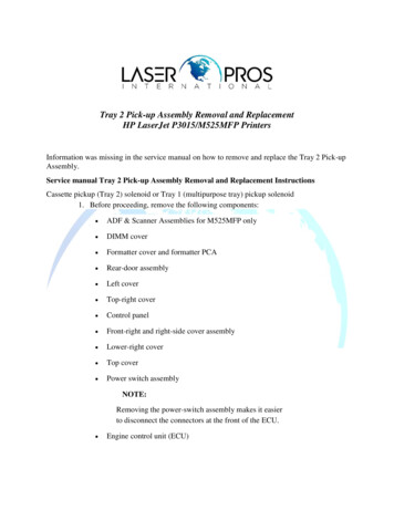
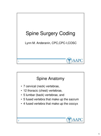
SpecMate Center Spine Cable Tray System LayoutStiffenerBar90 HorizontalElbowVertical PivotConnectorFiberReadyCable DropoutTray to BoxConnectorBlind nectorCenter SpineCable TrayAll rungs are factory fittedwith protective caps.A Series Tray installed in raisedfloor application.Rungs extruded withinternal screw threadsprovide direct connectionfor mounting accessories.2
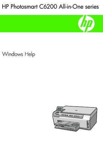
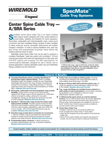
SpecMate A Series Center Spine Cable Tray System Layout with FiberReady FittingsStiffenerBar90 HorizontalElbowFiberReadyVertical PivotConnectorFiberReadyRungAdaptorFiberReadyField TeeTray to BoxConnectorFiberReadyHorizontal able o-ThruCrossBlind EndCenter SpineCable TrayCable Drop Out Fitting on12" [305mm] A Seriestray, shown to the left,maintains radius evenunder heavy load.ATR/SATR Series top rungconfiguration offers a single channel.Available up to 18" [457mm] wide.3Innovative Spine andscrew-in removable,replaceable andinterchangeable rungsoffer unparalleled cablemanagement options.
SpecMate Center Spine Cable Tray FittingsItem*WidthHeightCatalog No.DescriptionSpecificationsRB(height)(width)1" [25mm] wideReplacement Rungs5/8" [16mm] wideReplacement RungsField removable, replaceable and interchangeablerungs provide flexibility for future expansion ormodification without removing the cables, thusallowing for true cable management. All rungs arefactory fitted with protective plastic caps.SRB(height)(width)Available Heights3" [76mm]4" [102mm]6" [152mm]Available Widths3" [76mm]4 1/2" [114mm]6" [152mm]9" [229mm]12" [305mm]15" [381mm]18" [457mm]0100ASCOSplice Connector0100ASSCSplit Splice ConnectorAllows the connection of any two pieces of A, B, C,D, and DD Series Tray. Hole in center accepts 1/2"[12.7mm] threaded rod for hanging.Allows the connection of any two pieces of A andB Series Tray after the center rod has been hung.Generally used to add a second tier of trayto an existing ntal PivotConnectorHorizontal PivotConnector with Rung0200AHPRFO(height)(width) FiberReady 2" [51mm]Radius Horizontal PivotConnector with Rung22(bend radius)AHE90(width) Custom 90 Horizontal Elbow4Allows any angle horizontal connection for all A, C,D, and DD Series Tray. For 90 or wider angles,the use of a Horizontal Pivot Connector withRung is recommended.Provides additional cable support on horizontalconnections for all A, C, D, and DD Series Tray.Can be used for any angle horizontal connection.Provides a 2" [51mm] radius, allows any anglehorizontal connection and provides additionalcable support on horizontal turns for all A andSRA Series trays.Allows for 90 horizontal turns with radii of 12"[305mm] or more. Made with two HorizontalPivots and one section of tray with 6" [152mm]rung spacing. Used for larger radius requirements.
SpecMate Center Spine Cable Tray FittingsItem*Catalog No.DescriptionSpecifications0200AVPCVertical PivotConnectorAllows for vertical bends for all A, SRA andB Series trays.0200AVPCFO(width)FiberReady2" [51mm] RadiusVertical PivotConnectorProvides a 2" [51mm] radius and allows for verticalbends for all A and SRA Series trays.ATRAYRA(height)FiberReady2" [51mm] RadiusRung AdaptorSlips onto any A or SRA Series rung and provides a2" [51mm] radius on either side for cable dropoutprotection or tee or cross transition.AFT(width)(rung spacing)Field TeeUsed to make a tee (or “Y” turn) in the field fortrays with 6", 9", 12" or 18" [152mm, 229mm,305mm, or 457mm] rung spacing.SRAFT(width)(rung spacing)Field TeeSame as above with 5/8" [16mm] wide SRA rungs.NOTE: A Field Cross may be formed by using two Field Tees. At each tee connection, a 1/2" [13mm] threaded rod should be utilized.AFTFO(width)(height)(rung spacing)FiberReady2" [51mm] RadiusField TeeSRAFTFO(width)(height)(rung spacing) FiberReady2" [51mm] RadiusField TeeProvides a 2" [51mm] cable bend radius on atee (or “Y” turn) made in the field. For trays with6", 9", 12" or 18" [152mm, 229mm, 305mm, or457mm] rung spacing.Same as above with 5/8" [16mm] wide rungs.NOTE: A Field Cross may be formed by using two Field Tees. At each tee connection, a 1/2" [13mm] threaded rod should be utilized for support.AMT(height)(main run width)(tee run width)(fitting radius)*Flo-Thru Tee* See “Fitting Radius Determination” page 10.5Tee (or “Y” turn) with no barrier between channels.
SpecMate Center Spine Cable Tray FittingsItem*MountingHeightCatalog No.DescriptionSpecificationsAMTFO(height)(main run width)(tee run width)(fitting radius)*FiberReady 2"[51mm] RadiusFlo-Thru TeeProvides a 2" [51mm] cable bend radius on a tee (or“Y” turn) with no barrier between channels.AMX(height)(main run width)(cross run width)(fitting radius)*Flo-Thru CrossTee, cross or “Y” turn with no barrierbetween channels.AMXFO(height)(main run width)(cross run width)(fitting radius)*FiberReady 2"[51mm] RadiusFlo-Thru CrossProvides a 2" [51mm] cable bend radius ona tee cross or “Y” turn with no barrierbetween channels.07(rung spacing)CCP(size of conduit)Connects conduit to tray.Consult factory to order.Custom ConduitConnectorJH(rung height)(lay-in width)(mounting height)J RungA single rung, bent in the shape of a “J”, supportscables on walls.GH(rung height)(lay-in width)(mounting height)G RungA single rung, bent in the shape of a “G”. Supportscables overhead and on * See “Fitting Radius Determination” page 10.6
SpecMate Center Spine Cable Tray FittingsItem*Catalog No.DescriptionSpecifications06(width)ACDOFiber ReadyCable DropoutExtruded aluminum fitting provides a 2" [51mm]cable bend radius for cables dropping out of allA, SRA and B Series trays.NOTE: (Width) should equal total size of tray. Example: 0612ACDO will provide one 6" [152mm] dropout.0504ASBRHanger Bracket05(width)ABE(height)Blind EndProvides support for the tray at any point otherthan at the splice connector without drilling. Mayalso be used to develop seismic restraint –consult factory. Hole is pre-punched to accept1/2" [12.7mm] threaded rod.Closes off the end of the tray.05(width)ATBC(height)0501ATWCTray to BoxConnectorProvides a frame for cables entering the trayfrom or through the wall.Tray to WallConnector/End Cap7Connects tray to wall. Also acts as an end capto close off end of center spine.
SpecMate Center Spine Cable Tray FittingsItem*Catalog No.DescriptionSpecifications09(height)AFSBFloor SupportBracketProvides support for trays used in raised floorapplications. Specify height from floor (to bottomof tray) required.09(maximum height)ASTBStiffener BarProvides additional support to offset eccentricloading. Furnished unpainted in aluminum1/4" x 2" [6mm x 51mm]. Specify length required.The stiffener bar is designed to allow approximately 8" [203mm] of tolerance as indicated inthe chart on the left.MaximumHeight18" [457mm]24" [610mm]30" [762mm]36" [914mm]42" [1.07m]48" [1.22m]54" [1.37m]60" [1.52m]MinimumHeight10" [254mm]16" [406mm]22" [559mm]28" [711mm]34" [864mm]40" [1.02m]46" [1.17m]52" [1.32m]0803ADVS3" [76mm] Divider StripProvides a barrier for 3" [76mm] high trays.0804ADVS4" [102mm] Divider StripProvides a barrier for 4" [102mm] high trays.0806ADVS6" [152mm] Divider StripProvides a barrier for 6" [152mm] high trays.All divider strips come in 12' [3.66m] sections.0801ASPX1" [25mm] SpineExtensionProvides a 1" [25mm] height extension for a12' [3.66m] length of A Series tray. (Extendsthe spine to 4" [102mm] to match 4" [102mm]high rungs.)0803ASPX3" [76mm] SpineExtensionProvides a 3" [76mm] extension for a 12' [3.66m]length of A Series tray. (Extend the spine to6" [152mm] to match 6" [152mm] high rungs.)8
SpecMate Center Spine Cable Tray Product Selection GuideEnd ViewSide View (section)1/2 TrayWidth5/8"[15.9mm]1"[25mm]13/16"[21mm]1/2 TrayWidth5/8"[15.9mm]1"[25mm]TrayDepthRung SpacingCATALOG NUMBERING LOGICSeries:SERIESACASRACSRAATRCATRSATRCSATRRung Spacing:Tray erall Tray mm][305mm][457mm][610mm][762mm][914mm]NOTE: Measured atinside of rungs asshown above.EXAMPLE CATALOG NUMBERTo order one 12' [3.66m] length of standard Center Spine Cable Tray, 3" [76mm] deep, 12" [305mm]rung spacing and 18" [457mm] wide with 1" [25mm] rungs, use catalog number:A1203Series:Rung Spacing:Tray Depth*:18Overall Tray Width:NOTE: Each section of tray is shipped with one splice connector and necessary hardware.* The height of the center spine is 3" [76mm]. If the spine is being used as a divider, aspine extender is needed to maintain full separation between channels on 4" [102mm]and 6" [152mm] deep tray. For 4" [102mm] deep tray use “0801ASPX”. For 6"[152mm] deep tray, use “0803ASPX”.** When ordering a tray 18" [457mm] in width or larger the use of a stiffener bar shouldbe considered to stabilize eccentric loading. Measured at inside of rungs.Custom Options for A and SRA Series TraysItemDescriptionSpecificationsCover — Screw DownTray covers are formed with a 1/2" [13mm]lip down the outside of the rung crossingover the entire tray and have another 1/2"[13mm] lip formed over the outside of theother rungs.Cover — HingedHinged covers are also available. Coverscan be provided with a full piano hinge formounting to the spine of the tray in the field.NOTE: Inside tray liners and decorative outside tray enclosures are also available for full lengths of cable tray only. For anaesthetic finish, tray enclosures may be painted to complement existing decor. Consult factory for details.9
SpecMate Center Spine Cable Tray Systems Technical DataNEMA LOAD/SPAN DESIGNATIONSNEMA Class Support Span12A12 ft.12B12 ft.12C12 ft.CSA LOAD CLASS CAPACITIES AT VARYING SUPPORT SPACINGSWorking Load*50 lb./ft.75 lb./ft.100 lb./ft.1.5mCSA ClassAC1D1E* The working load is the total weight of all cablesand tubing to be placed in the tray.Support Spacing2.0m2.5mWorking 59kg/mN/AN/A3.037kg/m97kg/m179kg/m299kg/mWhen designing, specifying or installing a cable tray system, please consider the following (from the Canadian Electrical Code,Appendix B 12-2202):a. Allowance for wind and snow loading should be included within the maximum design load.b. Some fittings (particularly horizontal elbows) may require additional support depending on the loading.Per NEMA Standard Publication VE-1, Cable Tray is designed as a support for power or control cables, or both, and is notintended or designed to be a walkway for personnel. The user is urged to display appropriate warnings against the use of thissupport as a walkway. Each section of tray has a warning label.SpecMate NEMA Load RatingsA, SRA Series Tray (12' [3.66mm] lengths)SpecMate CSA Load RatingsCA Series Tray (10' [3m] lengths)TrayDepth3" [76mm], 4" [102mm]6" [152mm]RungSpacing6" [152mm], 9" [229mm],12" [305mm], 18" [457mm]TrayWidth18" [457mm], 24" [610mm],30" [762mm], 36"[914mm]NEMARating12BTrayDepth3" [76mm], 4" [102mm]6" [152mm]RungSpacing6" [152mm], 9" [229mm],12" [305mm], 18" [457mm]TrayWidth24" [610mm],30" [762mm], 36"[914mm]CSARatingC13" [76mm], 4" [102mm]6" [152mm]18" [457mm]12" [305mm]12B3" [76mm], 4" [102mm]6" [152mm]6" [152mm], 9" [229mm],12" [305mm], 18" [457mm]6" [152mm], 9" [229mm],12" [305mm], 18" [457mm]D13" [76mm], 4" [102mm]6" [152mm]6" [152mm], 9" [229mm],12" [305mm], 18" [457mm]6" [152mm], 9" [229mm]12C3" [76mm], 4" [102mm]6" [152mm]6" [152mm], 9" [229mm],12" [305mm]12" [305mm]12CNOTE: All SpecMate ATR and SATR trays are NEMA 12B rated.All SpecMate CATR and CSATR tray is CSA C1 rated.All ratings represent a 1.5 x safety factor.SpecMate CSA Load RatingsCSRA Series Tray (10' [3m] lengths)TrayDepth3" [76mm], 4" [102mm]6" [152mm]RungSpacing6" [152mm], 9" [229mm],12" [305mm], 18" [457mm]Standard MaterialCable Tray Spine, Rungs and Fittings: 6063T6 Aluminum AlloyLiners and Covers: 5052 Aluminum Alloyd u cMember of:Fitting Radius Determinationeveral Cable Tray fittings require that a “fitting radius” bespecified upon ordering. It is not necessary that this “fittingradius” match the width of the cable tray being used. Rather,the “fitting radius” must be sized to accommodate the bend radiusand stiffness of the cables that will be run in the system and must beequal to or greater than the cable manufacturer’s recommendedminimum bend radius for the largest cable anticipated to beinstalled in the cable tray. When several cables are to be installedin the same cable tray run, consider a larger “fitting radius” to easecable installation. Consult the cable manufacturer for theirrecommended minimum bend radius for each individual cable.PLEASE NOTE: The overall physical dimensions of a Cable TrayFitting increase dramatically as the specified “fitting radius” ofa cable tray fitting increases. This factor, as well as cost, makesthe selection of the smallest acceptable “fitting radius” the mostdesirable. When larger radius fittings are required, the entirecable tray system layout must be designed to allow adequatespace. Please consult the factory for further details.S10FittingRadiusTrayWidth6" [152mm], 9"[229mm],12" [305mm], 18" [457mm],24" [610mm], 30" [762mm],36" [914mm]CSARatingC1Third Party CertificationsUL File No. E140705CSA File No. 100837
Center Spine Cable Tray Wire Fill CapacityCABLE/WIRE TYPECATEGORY/WIRE SIZEUNSHIELDEDTWISTED PAIRCat 3, 4-pair,Cat 5, 4-pair,Cat 5e, 4-pair,Cat 6, 4-pair,SHIELDEDTWISTED PAIRType 1Type 2Type 324 AWG24 AWG24 AWG24 AWGNUMBER OF WIRES (Height x Width)3 x 18 3 x 243 x 303 x 364x6[mm]3x63x93 x 124x94 x 191153444288288232595386386310896582582467100 .8]309468627944126215791896415627838TWINAXIALFIBER OPTIC24 AWG24AWG24 AWG24 AWGO.D.InchesDuplex MultimodeCenter Spine Cable Tray Wire Fill CapacityCABLE/WIRE TYPECATEGORY/WIRE SIZEUNSHIELDEDTWISTED PAIRCat 3, 4-pair,Cat 5, 4-pair,Cat 5e, 4-pair,Cat 6, 4-pair,SHIELDEDTWISTED PAIRType 1Type 2Type 324 AWG24 AWG24 AWG24 AWG4 x 184 x 244 x 304 x 366 x 306 x 431882100 Ohm41855869983920731341862883910491260Duplex Multimode LFIBER OPTIC24 AWG24AWG24 AWG24 AWG(continued)NUMBER OF WIRES (Height x Width)6x66x96 x 126 x 186 x 24NOTE: Values are based on fill capacity only – cable weights must also be checked to ensure that load capacity of the tray is not exceeded.Fill values are based on NEC fill requirement stating a maximum allowable fill of 50% of tray cross sectional area. In reality, this is a fullyloaded tray due to spaces between cables.11
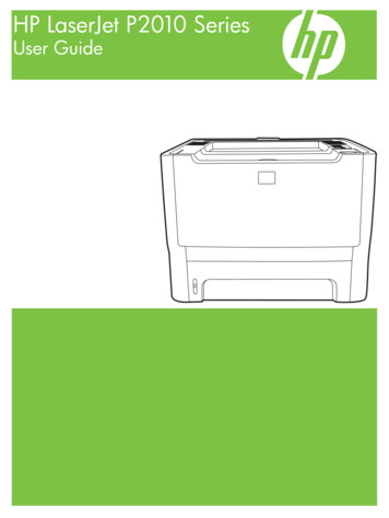
FiberReady 2" Radius FittingsFiberReady Vertical Pivot Connector.FiberReady Horizontal Pivot Connector with Rung.FiberReady Field Cross Fitting (consists oftwo field tees).Wiremold / LegrandU.S. and International:60 Woodlawn Street West Hartford, CT 061101-800-621-0049 FAX 860-232-2062 Outside U.S. 860-233-6251Canada:570 Applewood Crescent Vaughan, Ontario L4K 4B41-800-723-5175 FAX 905-738-9721 Copyright 2005 Wiremold / Legrand All Rights ReservedED691R3 – Updated August 2005 – For latest specs visit www.wiremold.com
3" [76mm] center spine serves as a barrier between services. The 3" [76mm] spine serves as a barrier separating one channel of the tray from the other when used with 3" [76mm] rungs. Spine extenders are available for use with 4" and 6" [102mm and 152mm] rungs as well as dividers to provide barriers within each channel. Center Spine Cable Tray: