Transcription
Intel Technology Journal Q1 99Defect-Based Test: A Key Enabler for Successful Migrationto Structural TestSanjay Sengupta, MPG Test Technology, Intel Corp.Sandip Kundu, MPG Test Technology, Intel Corp.Sreejit Chakravarty, MPG Test Technology, Intel Corp.Praveen Parvathala, MPG Test Technology, Intel Corp.Rajesh Galivanche, MPG Test Technology, Intel Corp.George Kosonocky, MPG Test Technology, Intel Corp.Mike Rodgers, MPG Test Technology, Intel Corp.TM Mak, MPG Test Technology, Intel Corp.Index words: structural test, functional test, ATE, DPM, logic test, I/O test, cache test, AC loopback test, inductive faultanalysis, fault models, stuck-at fault, bridge fault, delay fault, open fault, defect-based test, ATPG, fault simulation, faultmodeling, DPM, test quality, fault grading, design-for-testAbstractIntel s traditional microprocessor test methodology,based on manually generated functional tests that areapplied at speed using functional testers, is facing serious challenges due to the rising cost of manual testgeneration and the increasing cost of high-speedtesters. If current trends continue, the cost of testinga device could exceed the cost of manufacturing it.We therefore need to rely more on automatic testpattern generation (ATPG) and low-cost structuraltesters.The move to structural testers, the new failure mechanisms of deep sub-micron process technologies, theraw speed of devices and circuits, and the compressedtime to quality requirements of products with shorterlifecycles and steeper production ramps are adding tothe challenges of meeting our yield and DPM goals.To meet these challenges, we propose augmenting thestructural testing paradigm with defect-based test.This paper discusses the challenges that are forcing usto change our testing paradigm, the challenges in testing the I/O, cache and logic portions of today s microprocessors, due to the paradigm shift, and the problems to be solved to automate the entire process tothe extent possible.IntroductionTraditionally, Intel has relied on at-speed functionaltesting for microprocessors as this kind of test hashistorically provided several advantages to screen defects in a cost-effective manner. Unlike other testmethods, functional testing does not require the behavior of the device under test (DUT) to be changedduring the test mode. Thus, functional testing allowsus to test a very large number of actual functionalpaths at speed using millions of vectors in a few milliseconds; to thoroughly test all device I/Os with testerper-pin ATE technology; and to test embedded cachesin a proper functional mode. In addition, the testing isdone in a noise environment comparable to systemoperation. However, functional testing is facing an increasing number of obstacles, forcing Intel to look atalternative approaches.We begin this paper by describing the problem of continuing with functional testing of microprocessors. Wethen define an alternative paradigm, which we callstructural test. Finally, the challenges that we face andthe problems that need to be solved to test the logic, I/O, and cache subsystems of the microprocessor tomake the alternative test method work are discussed.Structural testing has been in use in the industry forquite some time. In order to meet Intel s aggressiveyield and DPM goals, we propose enhancing the structural test flow, by using defect-based test (DBT). DBTis based on generating manufacturing tests that targetactual physical defects via realistic fault models. Theprimary motivation in augmenting structural testing withDBT is to make up for some of the potential qualitylosses in migration to structural test methods as well asto meet the challenges of sub-micron defect behavioron the latest high-performance microprocessor circuits.Although the impact of DBT on defects per millionproducts shipped is not well characterized, prelimi-Defect-Based Test: A Key Enabler for Successful Migration to Structural Test1
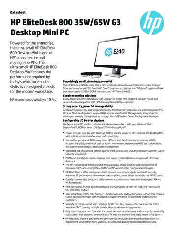
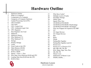
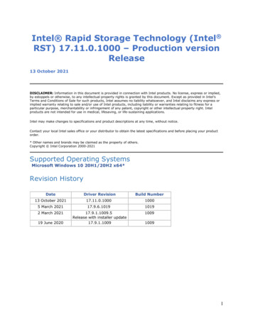
Intel Technology Journal Q1 99nary studies of DBT [1] show that it improves quality.DBT requires a whole suite of CAD tools for its successful application. In section 5, we discuss tool requirements for successful DBT for the latest high-performance microprocessors.trends for device period, overall tester timing accuracy (OTA), and the resulting percentage yield loss.It was derived from information in the SIA roadmap.The Microprocessor Test ProblemStated simply, the increasing cost of testing microprocessors to deliver acceptable product quality on everfaster and more complex designs is the main problemwe face. The cost challenges range from the nonrecurring design and product engineering investmentto generate good quality tests to the capital investmentfor manufacturing equipment for test.Automatic Test Equipment (ATE) CostFollowing Moore s Law for the past two decades,the silicon die cost of integrated circuits has decreasedas the number of transistors per die has continued toincrease. In contrast, during the same period, the costof testing integrated circuits in high-volume manufacturing has been steadily increasing. Silicon IndustryAssociation (SIA) forecasts, depicted in Figure 1, predict that the cost of testing transistors will actually surpass the cost of fabricating them within the next twodecades [2].Figure 1: Fabrication and test cost trendsLagging ATE TechnologyAggressive performance targets of Intel s chip set andmicroprocessor products also require increasinglyhigher bus bandwidth. Due to problems such as powersupply regulation, temperature variation, and electrical parasitics, tester timing inaccuracies continue torise as a function of the shrinking clock periods of highperformance designs. The graph in Figure 2 showsFigure 2: Tester accuracy and projected yield losstrendsIn addition to the increase in device frequency and thenumber of I/O pins, advanced signaling techniques arealso used to improve I/O performance. One such signaling innovation is the use of the source-synchronousbus, which has been in use since the Pentium Proline of microprocessors. Data on such a bus is sentalong with a clock (strobe) generated from the drivingdevice. This complicates testing since the ATE needsadded capability to synchronize with the bus clock(strobe).Test Generation EffortManual test writing, which has been in use at Intel,requires a good understanding of the structure of theDUT (typically a design block owned by a designer),as well as global knowledge of the micro-architecture. The latter is required since tests have to be fedto the DUT and the response read from the DUT.With increasing architectural complexities such as deeppipelining and speculative execution, increasing circuitdesign complexity and new failure modes, the cost oftest writing is expected to become unacceptable if weare to meet time-to-volume targets. This is supportedby the data presented in Figure 3 where manual testgeneration effort is compared with the effort requiredif ATPG, augmented with some manual test generation, were used. Note that manual test writing effortrequired for functional testing has been increasing exponentially over the last several generations of microprocessors at Intel. Compared to that, the projectionfor ATPG is very small. Note that the data forWillamette/Merced and beyond are projections.Defect-Based Test: A Key Enabler for Successful Migration to Structural Test2
Intel Technology Journal Q1 99Figure 3: Test generation effort trendDeep Sub-Micron TrendsAs the feature length of transistors scales down, powersupply voltage is scaled down with it, thereby reducing noise tolerance. Metal pitch is also scaled in tandem to realize the density gain. If interconnects werescaled proportionately in both pitch and height, lineresistivity would rise quadratically, thereby degradingperformance. To hold this trend down, metal height isscaled down by a smaller factor than the pitch, whichresults in increased cross capacitance.The increase in the number of metal layers introducesmore masking steps and can skew the random defectdistribution towards interconnect failure modes suchas bridges and open vias. Susceptibility to processvariation is heightened due to the higher cross capacitance and reduced noise tolerance.Like other CAD tools, performance validation toolsare struggling to keep up with increasing design sizesand circuit design complexity. The most common solution is to build simplifying assumptions into the tools,and to offset this by the use of conservative nominaldelays. Faced with increasing performance goals,designers build devices with negative timing margins.Such aggressive designs styles, coupled with increasing layout density, mean that even minor defects orprocess variations, which would otherwise be benign,could result in failures. Deliberate design marginalitythus translates into test problems. Writing functionaltests for subtle failure modes, which are made manifest under a very specific set of conditions, is becoming increasingly difficult.Test Paradigm Shift and Challenges of the NewTest ParadigmTest paradigms are defined by (a) the kind of test; (b)the kind of tester that stores and delivers the test; and(c) the test delivery mechanisms.Tests can be either structural or functional. Structural tests target manufacturing defects and attempt toensure the manufacturing correctness of basic devicessuch as wires, transistors, etc. Functional tests, on theother hand, target device functionality and attempt toensure that the device is functioning correctly. Functional tests are written primarily for architectural verification and silicon debug. They can be used for manufacturing testing also, as is done at Intel. Structuraltests, on the other hand, are used primarily for manufacturing testing.Testers come in two varieties: functional and structural. Functional testers can drive a large number ofI/O pins at high clock rates with great timing accuracy.On the other hand, structural testers are limited in thenumber of I/O pins they can drive, as well as thespeed and accuracy with which they can deliver datato the I/O pins. The cost of structural testers is considerably lower than the cost of functional testers.Tests can be delivered in one of two ways. Thedevice s normal functional channels are used and thedevice runs at operating speed. Alternatively, specialdesign-for-test (DFT) channels can be designed, andtests are applied through these channels at less thanoperational speed. The scan structure and ArrayDATexemplify this.The test paradigm in use at Intel so far uses functionaltesters and functional tests. These tests are deliveredusing the functional channels. Functional tests are written manually. Using functional testers requires hugecapital investment over short periods of time since theybecome obsolete very quickly. Hence, Intel is nowrelying more on reusable low-cost testers.As the data showed, manual test writing for future microprocessors is not feasible. Therefore, use of ATPGtools becomes essential to meet cost and time-to-quality requirements. Thus, the paradigm that has evolvedis to use low cost structural testers and use ATPG togenerate the required tests. The tests being generatedare structural tests. The structural tests we generatediffer from the classical structural tests in that we target defects via some novel fault models. We elaborate on this later in the paper. We next discuss thechallenges that this paradigm shift brings with it.Test GenerationThe loss in accessibility to the I/O pins of the devicehas a major impact on the ability of engineers to writefunctional tests for the chip. It may be possible toDefect-Based Test: A Key Enabler for Successful Migration to Structural Test3
Intel Technology Journal Q1 99load functional tests through direct access to an onchip cache, and run them from there, but it is difficultto generate tests that operate under this mode. As aresult, most of the fault-grading tests that are appliedthrough DFT methods have to be generated usingATPG tools.ATPG for large high-performance designs poses uniqueproblems. Today s microprocessors have multipleclock domains, operating at different speeds. Clockgating for low-power operation is pervasive. Typicaldesigns have many complex embedded arrays thatneed to be modeled for the ATPG tool. Industry standard DFT techniques, such as full scan, are often tooexpensive in either die area, or performance or both[7].Defect mechanisms in deep sub-micron designs areoften manifested as speed failures under very specificconditions. Most commercial ATPG tools, which arebased on the stuck-at and transition fault models, arenot equipped to handle these complex failure modes.Design for TestAlthough ATPG technology has progressed during thistime, the success of these tools is predicated on providing a high degree of access, controllability, andobservability to the internals of the design by usingDFT techniques.Scan design, the best-known structured DFT technique, comes at the cost of both performance and area,although some trade-off is possible. In order to meettight timing requirements, high-performance designstend to have very few gates between storage elements,which results in a high latch-to-logic ratio. Therefore,implementing scan DFT generally translates into sacrificing considerable silicon real estate.Another DFT technique that is gaining acceptance inthe industry is Built-In Self-Test (BIST), which incorporates mechanisms to generate stimuli and compressresponses for later off-chip comparisons into the design. BIST allows a large number of patterns to beapplied at speed in a short time, with very little testersupport. However, most logic BIST techniques thatenjoy commercial success today require full scan, orclose to it. In addition, they need design changes toenhance random-pattern testability, to allow at-speedtest application, and to prevent the system from getting into an unknown state that can corrupt the compressed response.Such intrusive DFT techniques cannot be appliedacross the board to high-performance devices, so logicBIST for microprocessors has only limited applicability today. High-volume, high-performance microprocessors have to choose between the high cost of scanDFT or resort to more custom access methods of get-ting stimuli to, and observing responses at, the boundaries of internal components.Test Application MethodologyIndustry data shows that testing a device using functional tests rather than other test patterns results infewer escapes [4]. A possible explanation is that whenthe device is exercised in functional mode, defects thatare not modeled, but affect device functionality, arescreened out.ATPG patterns differ fundamentally from functional testpatterns: they explicitly target faults rather than checking for them by exercising the functionality of the device, and they are typically very efficient, detecting eachfault fewer times in fewer ways. Also, since they arebased on using DFT structures to apply tests, they areapplied at a lower speed. Consequently, there is arisk of losing collateral coverage of defects that donot behave like the modeled faults.Structural testers have a small set of pins that operateat a lower frequency than the device and contact onlya subset of its I/O pins. The device needs to beequipped with special DFT access ports to load andunload the vectors from the tester. The boundary scantest access port, scan input and output pins, and direct access test buses are typically for this purpose.A few seconds of functional test may apply millions ofpatterns to a chip. In contrast, due to power, noise,and tester bandwidth considerations, the serial loading of test vectors from the DFT ports may be slow,and the number of test vectors that can be appliedfrom the structural tester may be far fewer than in afunctional test environment. This has implications forthe quality of the structural test set.Speed TestUnlike many standard parts, microprocessors arebinned for speed. This necessitates speed test, wherethe objective is to determine the maximum frequencyat which the part can be operated. In the past, a smallset of the worst speed paths was identified, and testswritten to exercise these paths were used to characterize the speed of the device. With increasing diesizes and shrinking device geometry, in-die processvariation is becoming significant. It is no longer safe toassume that all paths will be affected equally, and alarger set of representative paths needs to be tested todetermine the maximum operating frequency.One of the implications of applying vectors in the DFTmode is that the device may not be tested in its nativemode of operation. Special-purpose clocking mechanisms are implemented to apply the tests to the targeted logic blocks after they have been loaded. Theelectrical conditions, background noise, temperature,and power supply may all be different in the DFT mode.Defect-Based Test: A Key Enabler for Successful Migration to Structural Test4
Intel Technology Journal Q1 99These factors introduce inaccuracies, necessitatingguard-bands, in measuring the speed of the device.Examples of defects are partial or spongy via, the presence of extra material between a signal line and theV line, etc. Fault models define the properties of theddI/O Timing Testteststhat will detect the faulty behavior caused by deTraditional I/O functional testing relies on the ability of fects. For example, stuck-at 1 tests for line a willthe tester to control and observe the data, timing, and detect the defect caused by a bridge between the siglevels of each pin connected to a tester channel. The nal line a and V .ddtesting of the I/O buffers can be divided into threeIthasbeenreportedin the literature [5] that tests thatbasic categories: timing tests (e.g., setup and valid timings), level tests (e.g., Vil and Vol specifications), and detect every stuck-at fault multiple times are better atstructural tests (e.g., opens and shorts). The timing closing DPM holes than are tests that detect each faultspecifications of the I/O buffers are tested during the only once. This approach, called N-detection, worksclass functional testing of the device. With the use of because each fault is generally targeted in several difstructural testers, dedicated pin electronics are no ferent ways, increasing the probability that the condilonger available on the tester to make timing measure- tions necessary to activate a particular defect will existwhen the observation path to the fault site opens up.ments on each I/O pin on the device.Assuming that the I/O circuit meets the design target Defect-based tests are derived using a more systemand that timing failures are results of defects at the I/O atic approach to the problem. First, the likely failurecircuits, the problem of testing complex timing becomes sites are enumerated. Each likely defect is thenone of screening for these defects, instead of the ac- mapped to the appropriate fault model. The resultingdefect-based fault list is targeted during ATPG. Teststual timing specification itself.generated in this way are used to complement vectorsgenerated using the stuck-at fault model. Unlike theDefect-Based Teststuck-at model that works off of the schematic dataApplicability of the Stuck-At Fault Modelbase, the starting point for defect-based test is the maskAlthough functional patterns are graded against the layout of the device under test. Layout-based faultsingle stuck-at fault model, it is well known that most enumeration is a cornerstone of defect-based test.real defects do not behave like stuck-at faults. In- The use of better fault models is expected to enhancestead, stuck-at fault coverage has been used as a stop- any test generation scheme (ATPG, built-in self-test,ping criterion for manual test writing with the knowl- or weighted random pattern generation) because itedge that the functional tests would catch other types provides a better metric for defect coverage than doesof defects that impact device functionality. This mea- the stuck-at fault model.sure of test quality worked quite well for a long time.However, in the recent past, there is conclusive data Although not a proven technology, defect-based testfrom sub-micron devices that proves that the outgoing is a strong contender for addressing some of the risksDPM can be further reduced by grading and devel- of migrating from functional to structural test. The DBToping functional tests using additional fault models such effort at Intel is aimed at proving the effectiveness andas bridges etc. Therefore, the success of the single viability of this approach. The following sections destuck-at fault model cannot be guaranteed as we move scribe the key problems that have to be solved, thespecific tooling challenges in automating defect-basedfurther into the sub-micron devices.test, and a system architecture showing DBT modulesThe quality of ATPG patterns is only as good as the in the overall CAD flow.quality of the targeted fault models. As the test environment forces the transformation from functional to Challenges of Defect-Based Teststructural testing, there is yet another strong case forthe development of better test metrologies than the Enumerating Defect Sitessimplified stuck-at fault model. Defect-based test The number of all possible defects on a chip is astroaddresses this risk by using better representations of nomical, and it is neither feasible nor worthwhile tothe underlying defects, and by focusing the limited struc- generate tests for all of them. Fault enumeration is thetural test budget on this realistic fault.task of identifying the most important defect sites andthen mapping them into fault models that can be tarWhat is Defect-Based Test?geted by fault simulation and ATPG tools.Before we define defect-based test, we distinguishbetween two terms: defect and fault model. Defectsare physical defects that occur during manufacturing.Defect-Based Test: A Key Enabler for Successful Migration to Structural Test5
Intel Technology Journal Q1 99To enumerate likely defect sites, we need to understand the underlying causes of defects. Broadly speaking, defects are caused by process variations or random localized manufacturing imperfections, both ofwhich are explained below: Process variations such as transistor channellength variation, transistor threshold voltage variation, metal interconnect thickness variation, andinter metal layer dielectric thickness variation havea big impact on device speed characteristics. Ingeneral, the effect of process variation shows upfirst in the most critical paths in the design, thosewith maximum and minimum delays.Random imperfections such as resistive bridgingdefects between metal lines, resistive opens onmetal lines, improper via formations, shallowtrench isolation defects, etc. are yet another sourceof defects. Based on the parameters of the defectand neighboring parasitic, the defect may resultin a static or an at-speed failure.Techniques used for the extraction of faults due to random defects and process variations may differ, but thefundamental approach is to identify design marginalities that are likely to turn into defects when perturbed.The output of a fault extraction tool is typically ordered by probability of occurrence.Defect ModelingTo test a device, we apply a set of input stimuli andmeasure the response of the circuit at an output pin.Manufacturing defects, whether random or systematic, eventually manifest themselves as incorrect values on output pins.Fault simulators and ATPG tools operate at the logicallevel for efficiency. A fault model is a logic level representation of the defect that is inserted at the defectlocation. The challenge of fault modeling is to strike abalance between accuracy and simplicity as explainedbelow: Accuracy. The output response of the logic-levelnetlist with the fault model inserted should closelyapproximate the output response of the defectivecircuit for all input stimuli.Simplicity. The fault model should be tractable,i.e., it should not impose a severe burden on faultsimulation and ATPG tools.During the model development phase, the effectiveness of alternative models is evaluated by circuit simulation. Vectors generated on the fault model are simulated at the circuit level in the neighborhood of thedefect site, using an accurate device-level model ofthe defect. However, due to the number of possibledefect sites and the complexity of circuit simulation,this can only be done for a small sample.Defect-Based Fault SimulationSimulation of defect-based models is conceptually similar to stuck-at fault simulation, with a couple of twists: The number of possible defect-based faults is orders of magnitude larger than stuck-at faults, sothe performance of the tool is highly degraded. Inorder to be effective, a defect-based fault simulator has to be at least an order of magnitude faster. Defect-based faults may involve interactions between nodes across hierarchical boundaries, making it impractical to use a hierarchical or mixedlevel approach to fault simulation. It is necessaryto simulate the entire design at once, which alsoimposes capacity and performance requirements.Defect-Based Test of Cache MemoriesBackground: The Growth of Caches for MicroprocessorsThe use of caches for mainstream microprocessorson Intel architectures, beginning in the early 90s withthe i486 processor, heralded a return to Intel s original technical core competency, silicon memories, albeit with several new twists. The embedded CPUcaches have increased in size from the 4K byte cacheof the i486 processor generation to 10s and 100s ofkilobytes on today s processors and to even largerembedded CPU caches being considered for the future. This has resulted in a steady increase in the fraction of overall memory transistors per CPU and in theamount of CPU cache die area throughout the lastdecade.A second key cache test challenge is the increasingnumber of embedded arrays within a CPU. The number of embedded memory arrays per CPU has gonefrom a handful on the i486 and i860 processors todozens on the more recent Pentium Pro andPentium II processor lines.Memory Testing Fundamentals: Beyond theStuck-At ModelThe commodity stand-alone memory industry, i.e.,DRAMs and 4T SRAMs, have evolved fairly complex sets of tests to thoroughly test simple designs(compared to the complexity of a modern microprocessor) [6]. The targeted fault behaviors includestuck-at, transition, coupling, and disturbs, and theresulting number of targeted tests per circuit, per transistor, or per fault primitive on a memory is much higherthan for digital logic devices. On VLSI logic, the chal-Defect-Based Test: A Key Enabler for Successful Migration to Structural Test6
Intel Technology Journal Q1 99lenge is to achieve stuck-at fault coverage in the upper90 percentile, while on stand-alone memories, the number of targeted tests per circuit component is typicallyin the 100s or more likely 1000s of accesses per bitwithin a robust memory test program.One reason for the greater complexity of memory testsis that at the core of a typical digital memory is a sensitive, small signal bit, bit bar, and sense amp circuitsystem. Even for stand-alone memories, access andtesting of the analog characteristics (e.g., gain, common mode rejection ratio, etc.) is not directly possibleand must be done indirectly through the digital interface of address and data control and observability. Alarge number of first order variables subtly affect theobservability of silicon memory defect behavior. Therefore, most memory vendors characterize each variantof a given product line empirically against a broad rangeof memory patterns before settling on the test suitethat meets quality and cost considerations for highvolume manufacturing. These characterization testsuites (also known as kitchen sink suites) consist ofnumerous algorithmic march patterns and different setsof cell stability tests (e.g., data retention, bump tests,etc).A key concept for robust memory testing is the logicalto physical mapping. On a given physical design of anarray, the physical adjacencies and ordering of bits,bit lines, word lines, decoder bits, etc., typically donot match the logical ordering of bits (such as an address sequence from bit 0 to bit 1 to highest orderbit. Memory tests are designed to be specifically structural where worst-case interactions of the implementedsilicon structures with true physical proximity areforced. Thus the true physical to logical mapping is asubsequent transform that must be applied to a givenmemory pattern in order to maximize its ability to sensitize and observe defects and circuit marginality.Correct and validated documentation to the downstream test writer of the actual physical-to-logicalmapping is as important as other design collateral.Embedded Cache Testing and DFT in theContext of Logic TechnologiesTesting of embedded caches also needs to considerthe context of related logic technologies. To start with,the basic embedded cache memory cell is typically asix transistor (6T) SRAM as compared to the moretypical DRAMs and four transistor (4T) SRAM ofthe stand-alone silicon memory industry. The 6TSRAM offers better robustness against soft errors andcan be thoroughly tested to acceptable quality levelswith somewhat simpler test suites. However, the critical motivating factor is that a 6T SRAM cell is feasible, within the context of a high-performance logicsilicon fabrication process technology, without additional process steps.The smaller size (area, # bits) and 6T cell of the embedded CPU cache make it less sensitive than thestand-alone commodity 4T SRAMs and DRAMs.This is somewhat offset by the fact that embeddedcaches are generally pushing the SRAM design window on a given fabrication technology for system performance reasons. Therefore, adequate testing ofembedded 6T SRAMs requires an optimal use of robust memory test techniques ta
Intel Technology Journal Q1 99 Defect-Based Test: A Key Enabler for Successful Migration to Structural Test 1 Defect-Based Test: A Key Enabler for Successful Migration to Structural Test Sanjay Sengupta, MPG Test Technology, Intel Corp. . As the data showed, manual test writing for future mi-croprocessors is not feasible. Therefore, use of ATPG