Transcription
OSPF v1.31 – Aaron Balchunas1- Open Shortest Path First OSPF (Open Shortest Path First)OSPF is a standardized Link-State routing protocol, designed to scaleefficiently to support larger networks.OSPF adheres to the following Link State characteristics: OSPF employs a hierarchical network design using Areas. OSPF will form neighbor relationships with adjacent routers in thesame Area. Instead of advertising the distance to connected networks, OSPFadvertises the status of directly connected links using Link-StateAdvertisements (LSAs). OSPF sends updates (LSAs) when there is a change to one of its links,and will only send the change in the update. LSAs are additionallyrefreshed every 30 minutes. OSPF traffic is multicast either to address 224.0.0.5 (all OSPFrouters) or 224.0.0.6 (all Designated Routers). OSPF uses the Dijkstra Shortest Path First algorithm to determinethe shortest path. OSPF is a classless protocol, and thus supports VLSMs.Other characteristics of OSPF include: OSPF supports only IP routing. OSPF routes have an administrative distance is 110. OSPF uses cost as its metric, which is computed based on thebandwidth of the link. OSPF has no hop-count limit.The OSPF process builds and maintains three separate tables: A neighbor table – contains a list of all neighboring routers. A topology table – contains a list of all possible routes to all knownnetworks within an area. A routing table – contains the best route for each known network.***All original material copyright 2007 by Aaron Balchunas (aaron@routeralley.com),unless otherwise noted. All other material copyright of their respective owners.This material may be copied and used freely, but may not be altered or sold without the expressed writtenconsent of the owner of the above copyright. Updated material may be found at http://www.routeralley.com.
OSPF v1.31 – Aaron Balchunas2OSPF NeighborsOSPF forms neighbor relationships, called adjacencies, with other routers inthe same Area by exchanging Hello packets to multicast address 224.0.0.5.Only after an adjacency is formed can routers share routing information.Each OSPF router is identified by a unique Router ID. The Router ID canbe determined in one of three ways: The Router ID can be manually specified. If not manually specified, the highest IP address configured on anyLoopback interface on the router will become the Router ID. If no loopback interface exists, the highest IP address configured onany Physical interface will become the Router ID.By default, Hello packets are sent out OSPF-enabled interfaces every 10seconds for broadcast and point-to-point interfaces, and 30 seconds for nonbroadcast and point-to-multipoint interfaces.OSPF also has a Dead Interval, which indicates how long a router will waitwithout hearing any hellos before announcing a neighbor as “down.” Defaultfor the Dead Interval is 40 seconds for broadcast and point-to-pointinterfaces, and 120 seconds for non-broadcast and point-to-multipointinterfaces. Notice that, by default, the dead interval timer is four times theHello interval.These timers can be adjusted on a per interface basis:Router(config-if)# ip ospf hello-interval 15Router(config-if)# ip ospf dead-interval 60***All original material copyright 2007 by Aaron Balchunas (aaron@routeralley.com),unless otherwise noted. All other material copyright of their respective owners.This material may be copied and used freely, but may not be altered or sold without the expressed writtenconsent of the owner of the above copyright. Updated material may be found at http://www.routeralley.com.
OSPF v1.31 – Aaron Balchunas3OSPF Neighbors (continued)OSPF routers will only become neighbors if the following parameters withina Hello packet are identical on each router: Area ID Area Type (stub, NSSA, etc.) Prefix Subnet Mask Hello Interval Dead Interval Network Type (broadcast, point-to-point, etc.) AuthenticationThe Hello packets also serve as keepalives to allow routers to quicklydiscover if a neighbor is down. Hello packets also contain a neighbor fieldthat lists the Router IDs of all neighbors the router is connected to.A neighbor table is constructed from the OSPF Hello packets, whichincludes the following information: The Router ID of each neighboring router The current “state” of each neighboring router The interface directly connecting to each neighbor The IP address of the remote interface of each neighbor(Reference: l original material copyright 2007 by Aaron Balchunas (aaron@routeralley.com),unless otherwise noted. All other material copyright of their respective owners.This material may be copied and used freely, but may not be altered or sold without the expressed writtenconsent of the owner of the above copyright. Updated material may be found at http://www.routeralley.com.
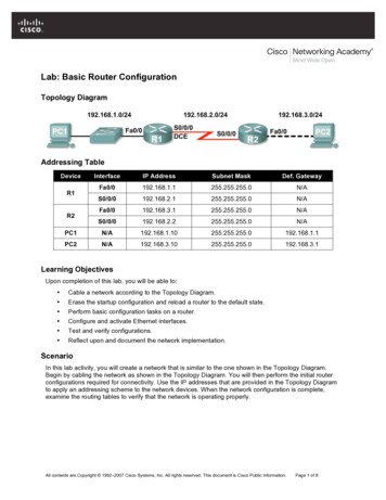
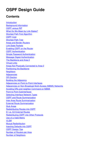
OSPF v1.31 – Aaron Balchunas4OSPF Designated RoutersIn multi-access networks such asEthernet, there is the possibility ofmany neighbor relationships on thesame physical segment. In the aboveexample, four routers are connectedinto the same multi-access segment.Using the following formula (where“n” is the number of routers):n(n-1)/2 .it is apparent that 6 separate adjacencies are needed for a fully meshednetwork. Increase the number of routers to five, and 10 separate adjacencieswould be required. This leads to a considerable amount of unnecessary LinkState Advertisement (LSA) traffic.If a link off of Router A were to fail, it would flood this information to allneighbors. Each neighbor, in turn, would then flood that same information toall other neighbors. This is a waste of bandwidth and processor load.To prevent this, OSPF will elect a Designated Router (DR) for each multiaccess networks, accessed via multicast address 224.0.0.6. For redundancypurposes, a Backup Designated Router (BDR) is also elected.OSPF routers will form adjacencies with the DR and BDR. If a changeoccurs to a link, the update is forwarded only to the DR, which thenforwards it to all other routers. This greatly reduces the flooding of LSAs.DR and BDR elections are determined by a router’s OSPF priority, whichis configured on a per-interface basis (a router can have interfaces inmultiple multi-access networks). The router with the highest prioritybecomes the DR; second highest becomes the BDR. If there is a tie inpriority, whichever router has the highest Router ID will become the DR.To change the priority on an interface:Router(config-if)# ip ospf priority 125Default priority on Cisco routers is 1. A priority of 0 will prevent the routerfrom being elected DR or BDR. Note: The DR election process is notpreemptive. Thus, if a router with a higher priority is added to the network, itwill not automatically supplant an existing DR. Thus, a router that shouldnever become the DR should always have its priority set to 0.***All original material copyright 2007 by Aaron Balchunas (aaron@routeralley.com),unless otherwise noted. All other material copyright of their respective owners.This material may be copied and used freely, but may not be altered or sold without the expressed writtenconsent of the owner of the above copyright. Updated material may be found at http://www.routeralley.com.
OSPF v1.31 – Aaron Balchunas5OSPF Neighbor StatesNeighbor adjacencies will progress through several states, including:Down – indicates that no Hellos have been heard from the neighboringrouter.Init – indicates a Hello packet has been heard from the neighbor, but twoway communication has not yet been initialized.2-Way – indicates that bidirectional communication has been established.Recall that Hello packets contain a neighbor field. Thus, communication isconsidered 2-Way once a router sees its own Router ID in its neighbor’sHello Packet. Designated and Backup Designated Routers are elected atthis stage.ExStart – indicates that the routers are preparing to share link stateinformation. Master/slave relationships are formed between routers todetermine who will begin the exchange.Exchange – indicates that the routers are exchanging Database Descriptors(DBDs). DBDs contain a description of the router’s Topology Database. Arouter will examine a neighbor’s DBD to determine if it has information toshare.Loading – indicates the routers are finally exchanging Link StateAdvertisements, containing information about all links connected to eachrouter. Essentially, routers are sharing their topology tables with each other.Full – indicates that the routers are fully synchronized. The topology table ofall routers in the area should now be identical. Depending on the “role” ofthe neighbor, the state may appear as: Full/DR – indicating that the neighbor is a Designated Router (DR) Full/BDR – indicating that the neighbor is a Backup DesignatedRouter (BDR) Full/DROther – indicating that the neighbor is neither the DR orBDROn a multi-access network, OSPF routers will only form Full adjacencieswith DRs and BDRs. Non-DRs and non-BDRs will still form adjacencies,but will remain in a 2-Way State. This is normal OSPF behavior.***All original material copyright 2007 by Aaron Balchunas (aaron@routeralley.com),unless otherwise noted. All other material copyright of their respective owners.This material may be copied and used freely, but may not be altered or sold without the expressed writtenconsent of the owner of the above copyright. Updated material may be found at http://www.routeralley.com.
OSPF v1.31 – Aaron Balchunas6OSPF Network TypesOSPF’s functionality is different across several different network topologytypes. OSPF’s interaction with Frame Relay will be explained in anothersectionBroadcast Multi-Access – indicates a topology where broadcast occurs. Examples include Ethernet, Token Ring, and ATM. OSPF will elect DRs and BDRs. Traffic to DRs and BDRs is multicast to 224.0.0.6. Traffic fromDRs and BDRs to other routers is multicast to 224.0.0.5. Neighbors do not need to be manually specified.Point-to-Point – indicates a topology where two routers are directlyconnected. An example would be a point-to-point T1. OSPF will not elect DRs and BDRs. All OSPF traffic is multicast to 224.0.0.5. Neighbors do not need to be manually specified.Point-to-Multipoint – indicates a topology where one interface can connectto multiple destinations. Each connection between a source and destinationis treated as a point-to-point link. An example would be Point-to-Multipoint Frame Relay. OSPF will not elect DRs and BDRs. All OSPF traffic is multicast to 224.0.0.5. Neighbors do not need to be manually specified.Non-broadcast Multi-access Network (NBMA) – indicates a topologywhere one interface can connect to multiple destinations; however,broadcasts cannot be sent across a NBMA network. An example would be Frame Relay. OSPF will elect DRs and BDRs. OSPF neighbors must be manually defined, thus All OSPF trafficis unicast instead of multicast.Remember: on non-broadcast networks, neighbors must be manuallyspecified, as multicast Hello’s are not allowed.***All original material copyright 2007 by Aaron Balchunas (aaron@routeralley.com),unless otherwise noted. All other material copyright of their respective owners.This material may be copied and used freely, but may not be altered or sold without the expressed writtenconsent of the owner of the above copyright. Updated material may be found at http://www.routeralley.com.
OSPF v1.31 – Aaron Balchunas7Configuring OSPF Network TypesThe default OSPF network type for basic Frame Relay is Non-broadcastMulti-access Network (NBMA). To configure manually:Router(config)# interface s0Router(config-if)# encapsulation frame-relayRouter(config-if)# frame-relay map ip 10.1.1.1 101Router(config-if)# ip ospf network non-broadcastRouter(config)# router ospf 1Router(config-router)# neighbor 10.1.1.1Notice that the neighbor was manually specified, as multicasting is notallowed on an NBMA. However, the Frame-Relay network can be trickedinto allowing broadcasts, eliminating the need to manually specifyneighbors:Router(config)# interface s0Router(config-if)# encapsulation frame-relayRouter(config-if)# frame-relay map ip 10.1.1.1 101 broadcastRouter(config-if)# ip ospf network broadcastNotice that the ospf network type has been changed to broadcast, and thebroadcast parameter was added to the frame-relay map command. Theneighbor no longer needs to be specified, as multicasts will be allowed outthis map.The default OSPF network type for Ethernet and Token Ring is BroadcastMulti-Access. To configure manually:Router(config)# interface e0Router(config-if)# ip ospf network broadcastThe default OSPF network type for T1’s (HDLC or PPP) and Point-to-PointFrame Relay is Point-to-Point. To configure manually:Router(config)# interface s0Router(config-if)# encapsulation frame-relayRouter(config)# interface s0.1 point-to-pointRouter(config-if)# frame-relay map ip 10.1.1.1 101 broadcastRouter(config-if)# ip ospf network point-to-point***All original material copyright 2007 by Aaron Balchunas (aaron@routeralley.com),unless otherwise noted. All other material copyright of their respective owners.This material may be copied and used freely, but may not be altered or sold without the expressed writtenconsent of the owner of the above copyright. Updated material may be found at http://www.routeralley.com.
OSPF v1.31 – Aaron Balchunas8Configuring OSPF Network Types (continued)The default OSPF network type for Point-to-Multipoint Frame Relay is stillNon-broadcast Multi-access Network (NBMA). However, OSPF supportsan additional network type called Point-to-Multipoint, which will allowneighbor discovery to occur automatically. To configure:Router(config)# interface s0Router(config-if)# encapsulation frame-relayRouter(config)# interface s0.2 multipointRouter(config-if)# frame-relay map ip 10.1.1.1 101 broadcastRouter(config-if)# ip ospf network point-to-multipointAdditionally, a non-broadcast parameter can be added to the ip ospf networkcommand when specifying point-to-multipoint.Router(config)# interface s0Router(config-if)# encapsulation frame-relayRouter(config)# interface s0.2 multipointRouter(config-if)# frame-relay map ip 10.1.1.1 101Router(config-if)# ip ospf network point-to-multipoint non-broadcastRouter(config)# router ospf 1Router(config-router)# neighbor 10.1.1.1Notice the different in configuration. The frame-relay map command nolonger has the broadcast parameter, as broadcasts and multicasts are notallowed on a non-broadcast network.Thus, in the OSPF router configuration, neighbors must again be manuallyspecified. Traffic to those neighbors will be unicast instead of multicast.OSPF network types must be set identically on two “neighboring” routers,otherwise they will never form an adjacency.***All original material copyright 2007 by Aaron Balchunas (aaron@routeralley.com),unless otherwise noted. All other material copyright of their respective owners.This material may be copied and used freely, but may not be altered or sold without the expressed writtenconsent of the owner of the above copyright. Updated material may be found at http://www.routeralley.com.
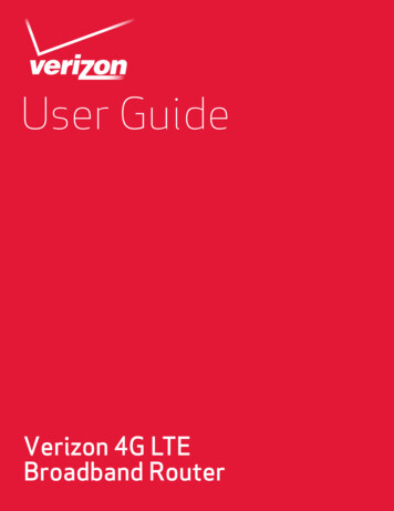
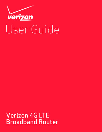
OSPF v1.31 – Aaron Balchunas9The OSPF HierarchyOSPF is a hierarchical system that separates an Autonomous System intoindividual areas. OSPF traffic can either be intra-area (within one area),inter-area (between separate areas), or external (from another AS).OSPF routers build a Topology Database of all links within their area, andall routers within an area will have an identical topology database. Routingupdates between these routers will only contain information about links localto their area. Limiting the topology database to include only the local areaconserves bandwidth and reduces CPU loads.Area 0 is required for OSPF to function, and is considered the “Backbone”area. As a rule, all other areas must have a connection into Area 0, thoughthis rule can be bypassed using virtual links (explained shortly). Area 0 isoften referred to as the transit area to connect all other areas.OSPF routers can belong to multiple areas, and will thus contain separateTopology databases for each area. These routers are known as Area BorderRouters (ABRs).Consider the above example. Three areas exist: Area 0, Area 1, and Area 2.Area 0, again, is the backbone area for this Autonomous System. Both Area1 and Area 2 must directly connect to Area 0.Routers A and B belong fully to Area 1, while Routers E and F belong fullyto Area 2. These are known as Internal Routers.Router C belongs to both Area 0 and Area 1. Thus, it is an ABR. Because ithas an interface in Area 0, it can also be considered a Backbone Router.The same can be said for Router D, as it belongs to both Area 0 and Area 2.***All original material copyright 2007 by Aaron Balchunas (aaron@routeralley.com),unless otherwise noted. All other material copyright of their respective owners.This material may be copied and used freely, but may not be altered or sold without the expressed writtenconsent of the owner of the above copyright. Updated material may be found at http://www.routeralley.com.
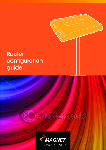
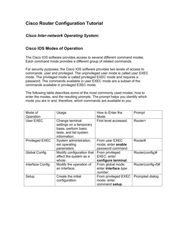
OSPF v1.31 – Aaron Balchunas 10The OSPF Hierarchy (continued)Now consider the above example. Router G has been added, which belongsto Area 0. However, Router G also has a connection to the Internet, which isoutside this Autonomous System.This makes Router G an Autonomous System Border Router (ASBR). Arouter can become an ASBR in one of two ways: By connecting to a separate Autonomous System, such as the Internet By redistributing another routing protocol into the OSPF process.ASBRs provide access to external networks. OSPF defines two “types” ofexternal routes: Type 2 (E2) – Includes only the external cost to the destinationnetwork. External cost is the metric being advertised from outside theOSPF domain. This is the default type assigned to external routes. Type 1 (E1) – Includes both the external cost, and the internal cost toreach the ASBR, to determine the total metric to reach the destinationnetwork. Type 1 routes are always preferred over Type 2 routes to thesame destination.Thus, the four separate OSPF router types are as follows: Internal Routers – all router interfaces belong to only one Area. Area Border Routers (ABRs) – contains interfaces in at least twoseparate areas Backbone Routers – contain at least one interface in Area 0 Autonomous System Border Routers (ASBRs) – contain aconnection to a separate Autonomous System***All original material copyright 2007 by Aaron Balchunas (aaron@routeralley.com),unless otherwise noted. All other material copyright of their respective owners.This material may be copied and used freely, but may not be altered or sold without the expressed writtenconsent of the owner of the above copyright. Updated material may be found at http://www.routeralley.com.
OSPF v1.31 – Aaron Balchunas 11LSAs and the OSPF Topology DatabaseOSPF, as a link-state routing protocol, does not rely on routing-by-rumor asRIP and IGRP do.Instead, OSPF routers keep track of the status of links within their respectiveareas. A link is simply a router interface. From these lists of links and theirrespective statuses, the topology database is created. OSPF routers forwardlink-state advertisements (LSAs) to ensure the topology database isconsistent on each router within an area.Several LSA types exist: Router LSA (Type 1) – Contains a list of all links local to the router, andthe status and “cost” of those links. Type 1 LSAs are generated by allrouters in OSPF, and are flooded to all other routers within the local area. Network LSA (Type 2) – Generated by all Designated Routers in OSPF,and contains a list of all routers attached to the Designated Router. Network Summary LSA (Type 3) – Generated by all ABRs in OSPF,and contains a list of all destination networks within an area. Type 3LSAs are sent between areas to allow inter-area communication to occur. ASBR Summary LSA (Type 4) – Generated by ABRs in OSPF, andcontains a route to any ASBRs in the OSPF system. Type 4 LSAs aresent from an ABR into its local area, so that Internal routers know how toexit the Autonomous System. External LSA (Type 5) – Generated by ASBRs in OSPF, and containroutes to destination networks outside the local Autonomous System.Type 5 LSAs can also take the form of a default route to all networksoutside the local AS. Type 5 LSAs are flooded to all areas in the OSPFsystem.Multicast OSPF (MOSPF) utilizes a Type 6 LSA, but that goes beyond thescope of this guide.Later in this section, Type 7 NSSA External LSAs will be described indetail.***All original material copyright 2007 by Aaron Balchunas (aaron@routeralley.com),unless otherwise noted. All other material copyright of their respective owners.This material may be copied and used freely, but may not be altered or sold without the expressed writtenconsent of the owner of the above copyright. Updated material may be found at http://www.routeralley.com.
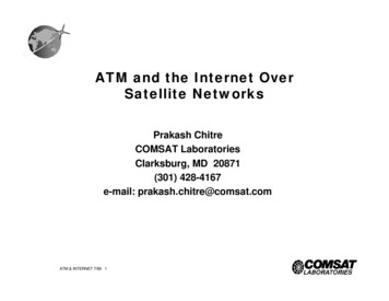
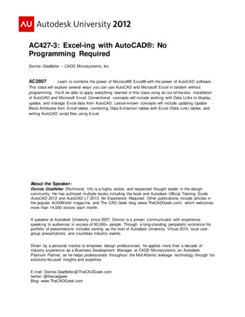
OSPF v1.31 – Aaron Balchunas 12LSAs and the OSPF Topology Database (continued)From the above example, the following can be determined: Routers A, B, E, and F are Internal Routers. Routers C and D are ABRs. Router G is an ASBR.All routers will generate Router (Type 1) LSAs. For example, Router Awill generate a Type 1 LSA that contains the status of links FastEthernet 0/0and FastEthernet 0/1. This LSA will be flooded to all other routers in Area 1.Designated Routers will generate Network (Type 2) LSAs. For example, ifRouter C was elected the DR for the multi-access network in Area 1, itwould generate a Type 2 LSA containing a list of all routers attached to it.Area Border Routers (ABRs) will generate Network Summary (Type 3)LSAs. For example, Router C is an ABR between Area 0 and Area 1. It willthus send Type 3 LSAs into both areas. Type 3 LSAs sent into Area 0 willcontain a list of networks within Area 1, including costs to reach thosenetworks. Type 3 LSAs sent into Area 1 will contain a list of networkswithin Area 0, and all other areas connected to Area 0. This allows Area 1 toreach any other area, and all other areas to reach Area 1.***All original material copyright 2007 by Aaron Balchunas (aaron@routeralley.com),unless otherwise noted. All other material copyright of their respective owners.This material may be copied and used freely, but may not be altered or sold without the expressed writtenconsent of the owner of the above copyright. Updated material may be found at http://www.routeralley.com.
OSPF v1.31 – Aaron Balchunas 13LSAs and the OSPF Topology Database (continued)ABRs will also generate ASBR Summary (Type 4) LSAs. For example,Router C will send Type 4 LSAs into Area 1 containing a route to theASBR, thus providing routers in Area 1 with the path out of theAutonomous System.ASBRs will generate External (Type 5) LSAs. For example, Router G willgenerate Type 5 LSAs that contain routes to network outside the AS. TheseType 5 LSAs will be flooded to routers of all areas.Each type of LSA is propagated under three circumstances: When a new adjacency is formed. When a change occurs to the topology table. When an LSA reaches its maximum age (every 30 minutes, bydefault).Thus, though OSPF is typically recognized to only send updates when achange occurs, LSA’s are still periodically refreshed every 30 minutes.***All original material copyright 2007 by Aaron Balchunas (aaron@routeralley.com),unless otherwise noted. All other material copyright of their respective owners.This material may be copied and used freely, but may not be altered or sold without the expressed writtenconsent of the owner of the above copyright. Updated material may be found at http://www.routeralley.com.
OSPF v1.31 – Aaron Balchunas 14The OSPF MetricOSPF determines the best (or shortest) path to a destination network using acost metric, which is based on the bandwidth of interfaces. The total cost ofa route is the sum of all outgoing interface costs. Lowest cost is preferred.Cisco applies default costs to specific interface types:TypeCostSerial (56K)Serial (64K)T1 (1.544Mbps)Token Ring (4Mbps)Ethernet (10 Mbps)Token Ring (16 Mbps)Fast Ethernet1785156264251061On Serial interfaces, OSPF will use the configured bandwidth (measured inKbps) to determine the cost:Router(config)# interface s0Router(config-if)# bandwidth 64The default cost of an interface can be superseded:Router(config)# interface e0Router(config-if)# ip ospf cost 5Changing the cost of an interface can alter which path OSPF deems the“shortest,” and thus should be used with great care.To alter how OSPF calculates its default metrics for interfaces:Router(config)# router ospf 1Router(config-router)# ospf auto-cost reference-bandwidth 100The above ospf auto-cost command has a value of 100 configured, which isactually the default. This indicates that a 100Mbps link will have a cost of 1(because 100/100 is 1). All other costs are based off of this. For example, thecost of 4 Mbps Token Ring is 25 because 100/4 25.***All original material copyright 2007 by Aaron Balchunas (aaron@routeralley.com),unless otherwise noted. All other material copyright of their respective owners.This material may be copied and used freely, but may not be altered or sold without the expressed writtenconsent of the owner of the above copyright. Updated material may be found at http://www.routeralley.com.
OSPF v1.31 – Aaron Balchunas 15Configuring Basic OSPFRouting protocol configuration occurs in Global Configuration mode. OnRouter A, to configure OSPF:RouterA(config)# router ospf 1RouterA(config-router)# router-id 1.1.1.1RouterA(config-router)# network 172.16.0.0 0.0.255.255 area 1RouterA(config-router)# network 172.17.0.0 0.0.255.255 area 0The first command, router ospf 1, enables the OSPF process. The “1”indicates the OSPF process ID, and can be unique on each router. Theprocess ID allows multiple OSPF processes to run on the same router. Therouter-id command assigns a unique OSPF ID of 1.1.1.1 for this router.Note the use of a wildcard mask instead of a subnet mask in the networkstatement. With OSPF, we’re not telling the router what networks toadvertise; we’re telling the router to place certain interfaces into specificareas, so those routers can form neighbor relationships. The wildcard mask0.0.255.255 tells us that the last two octets can match any number.The first network statement places interface E0 on Router A into Area 1.Likewise, the second network statement places interface S0 on Router A intoArea 0. The network statement could have been written more specifically:RouterA(config)# router ospf 1RouterA(config-router)# network 172.16.1.2 0.0.0.0 area 1RouterA(config-router)# network 172.17.1.1 0.0.0.0 area 0In order for Router B to form a neighbor relationship with Router A, itsconnecting interface must be put in the same Area as Router A:RouterB(config)# router ospf 1RouterA(config-router)# router-id 2.2.2.2RouterB(config-router)# network 172.17.1.2 0.0.0.0 area 0RouterB(config-router)# network 172.18.1.1 0.0.0.0 area 2If Router B’s S0 interface was placed in a different area than Router A’s S0interface, the two routers would never form a neighbor relationship, andnever share routing updates.***All original material copyright 2007 by Aaron Balchunas (aaron@routeralley.com),unless otherwise noted. All other material copyright of their respective owners.This material may be copied and used freely, but may not be altered or sold without the expressed writtenconsent of the owner of the above copyright. Updated material may be found at http://www.routeralley.com.
OSPF v1.31 – Aaron Balchunas 16OSPF Passive-InterfacesIt is possible to control which router interfaces will participate in the OSPFprocess. Just as with EIGRP and RIP, we can use the passive-interfacecommand.However, please note that the passive-interface command works differentlywith OSPF than with RIP or IGRP. OSPF will no longer form neighborrelationships out of a “passive” interface, thus this command preventsupdates from being sent or received out of this interface:RouterC(config)# router ospf 1RouterC(config-router)# network 10.4.0.0 0.0.255.255 area 0RouterC(config-router)# network 10.2.0.0 0.0.255.255 area 0RouterC(config-router)# passive-interface s0Router C will not form a neighbor adjacency with Router B.It is possible to configure all interfaces to be passive using the passiveinterface default command, and then individually use the no passiveinterface command on the interfaces that neighbors should be formed on:RouterC(config)# router ospf 1RouterC(config-router)# network 10.4.0.0 0.0.255.255 area 0RouterC(config-router)# network 10.2.0.0 0.0.255.255 area 0RouterC(config-router)# passive-interface defaultRouterC(config-router)# no passive-interface e0Always remember, that the passive-interface command will prevent OSPF(and EIGRP) from forming neighbor relationships out of that interface. Norouting updates are passed in either direction.***All original material copyright 2007 by Aaron Balchunas (aaron@routeralley.com),unless otherwise noted. All other material copyright of their respective owners.This material may be copied and used freely, but may not be altered or sold without the expressed writtenconsent of the owner of the above copyright. Updated material may be found at http://www.routeralley.com.
OSPF v1.31 – Aaron Balchunas 17OSPF AuthenticationOSPF supports authentication to secure routing updates. However, OSPFauthentication is configured differently than RIP or EIGRP authentication.Two forms of OSPF authentication exist, using either clear-text or an MD5hash. To configure clear-text authentication, the first step is to enableauthentication for the area, under the OSPF routing process:RouterA(config)# router ospf 1RouterA(config-router)# network 172.17.0.0 0.0.255.255 area 0RouterA(config-router)# area 0 a
OSPF v1.31 - Aaron Balchunas * * * All original material copyright 2007 by Aaron Balchunas ( aaron@routeralley.com ), unless otherwise noted. All other material .