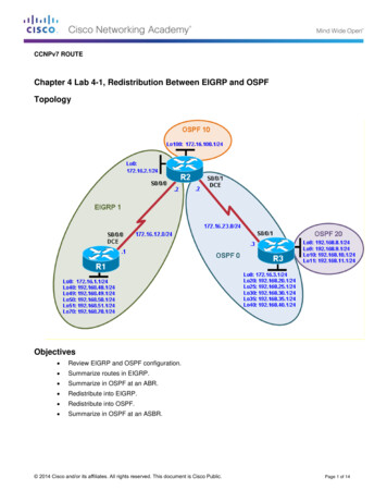
Transcription
OSPF Design GuideContentsIntroductionBackground InformationOSPF versus RIPWhat Do We Mean by Link-States?Shortest Path First AlgorithmOSPF CostShortest Path TreeAreas and Border RoutersLink-State PacketsEnabling OSPF on the RouterOSPF AuthenticationSimple Password AuthenticationMessage Digest AuthenticationThe Backbone and Area 0Virtual LinksAreas Not Physically Connected to Area 0Partitioning the BackboneNeighborsAdjacenciesDR ElectionBuilding the AdjacencyAdjacencies on Point-to-Point InterfacesAdjacencies on Non-Broadcast Multi-Access (NBMA) NetworksAvoiding DRs and neighbor Command on NBMAPoint-to-Point SubinterfacesSelecting Interface Network TypesOSPF and Route SummarizationInter-Area Route SummarizationExternal Route SummarizationStub AreasRedistributing Routes into OSPFE1 vs. E2 External RoutesRedistributing OSPF into Other ProtocolsUse of a Valid MetricVLSMMutual RedistributionInjecting Defaults into OSPFOSPF Design TipsNumber of Routers per AreaNumber of Neighbors
Number of Areas per ABRFull Mesh vs. Partial MeshMemory IssuesSummaryAppendix A: Link-State Database SynchronizationLink-State AdvertisementsOSPF Database ExampleAppendix B: OSPF and IP Multicast AddressingAppendix C: Variable Length Subnet Masks (VLSM)Related InformationIntroductionThe Open Shortest Path First (OSPF) protocol, defined in RFC 2328, is an Interior GatewayProtocol used to distribute routing information within a single Autonomous System. This paperexamines how OSPF works and how it can be used to design and build large and complicatednetworks.Background InformationOSPF protocol was developed due to a need in the internet community to introduce a highfunctionality non-proprietary Internal Gateway Protocol (IGP) for the TCP/IP protocol family. Thediscussion of the creation of a common interoperable IGP for the Internet started in 1988 and didnot get formalized until 1991. At that time the OSPF Working Group requested that OSPF beconsidered for advancement to Draft Internet Standard.The OSPF protocol is based on link-state technology, which is a departure from the Bellman-Fordvector based algorithms used in traditional Internet routing protocols such as RIP. OSPF hasintroduced new concepts such as authentication of routing updates, Variable Length SubnetMasks (VLSM), route summarization, and so forth.These chapters discuss the OSPF terminology, algorithm and the pros and cons of the protocol indesigning the large and complicated networks of today.OSPF versus RIPThe rapid growth and expansion of today's networks has pushed RIP to its limits. RIP has certainlimitations that can cause problems in large networks: RIP has a limit of 15 hops. A RIP network that spans more than 15 hops (15 routers) isconsidered unreachable.RIP cannot handle Variable Length Subnet Masks (VLSM). Given the shortage of IPaddresses and the flexibility VLSM gives in the efficient assignment of IP addresses, this isconsidered a major flaw.Periodic broadcasts of the full routing table consume a large amount of bandwidth. This is amajor problem with large networks especially on slow links and WAN clouds.
RIP converges slower than OSPF. In large networks convergence gets to be in the order ofminutes. RIP routers go through a period of a hold-down and garbage collection and slowlytime-out information that has not been received recently. This is inappropriate in largeenvironments and could cause routing inconsistencies.RIP has no concept of network delays and link costs. Routing decisions are based on hopcounts. The path with the lowest hop count to the destination is always preferred even if thelonger path has a better aggregate link bandwidth and less delays.RIP networks are flat networks. There is no concept of areas or boundaries. With theintroduction of classless routing and the intelligent use of aggregation and summarization, RIPnetworks seem to have fallen behind.Some enhancements were introduced in a new version of RIP called RIP2. RIP2 addresses theissues of VLSM, authentication, and multicast routing updates. RIP2 is not a big improvement overRIP (now called RIP 1) because it still has the limitations of hop counts and slow convergencewhich are essential in todays large networks. OSPF, on the other hand, addresses most of the issues previously presented:With OSPF, there is no limitation on the hop count.The intelligent use of VLSM is very useful in IP address allocation.OSPF uses IP multicast to send link-state updates. This ensures less processing on routersthat are not listening to OSPF packets. Also, updates are only sent in case routing changesoccur instead of periodically. This ensures a better use of bandwidth.OSPF has better convergence than RIP. This is because routing changes are propagatedinstantaneously and not periodically.OSPF allows for better load balancing.OSPF allows for a logical definition of networks where routers can be divided into areas. Thislimits the explosion of link state updates over the whole network. This also provides amechanism for aggregating routes and cutting down on the unnecessary propagation ofsubnet information.OSPF allows for routing authentication by using different methods of password authentication.OSPF allows for the transfer and tagging of external routes injected into an AutonomousSystem. This keeps track of external routes injected by exterior protocols such as BGP.This of course leads to more complexity in the configuration and troubleshooting of OSPFnetworks. Administrators that are used to the simplicity of RIP are challenged with the amount ofnew information they have to learn in order to keep up with OSPF networks. Also, this introducesmore overhead in memory allocation and CPU utilization. Some of the routers running RIP mighthave to be upgraded in order to handle the overhead caused by OSPF. What Do We Mean by Link-States?OSPF is a link-state protocol. We could think of a link as being an interface on the router. Thestate of the link is a description of that interface and of its relationship to its neighboring routers. Adescription of the interface would include, for example, the IP address of the interface, the mask,the type of network it is connected to, the routers connected to that network and so on. Thecollection of all these link-states would form a link-state database.Shortest Path First Algorithm
OSPF uses a shorted path first algorithm in order to build and calculate the shortest path to allknown destinations.The shortest path is calculated with the use of the Dijkstra algorithm. Thealgorithm by itself is quite complicated. This is a very high level, simplified way of looking at thevarious steps of the algorithm:1. Upon initialization or due to any change in routing information, a router generates a link-stateadvertisement. This advertisement represents the collection of all link-states on that router.2. All routers exchange link-states by means of flooding. Each router that receives a link-stateupdate should store a copy in its link-state database and then propagate the update to otherrouters.3. After the database of each router is completed, the router calculates a Shortest Path Tree toall destinations. The router uses the Dijkstra algorithm in order to calculate the shortest pathtree. The destinations, the associated cost and the next hop to reach those destinations formthe IP routing table.4. In case no changes in the OSPF network occur, such as cost of a link or a network beingadded or deleted, OSPF should be very quiet. Any changes that occur are communicatedthrough link-state packets, and the Dijkstra algorithm is recalculated in order to find theshortest path.The algorithm places each router at the root of a tree and calculates the shortest path to eachdestination based on the cumulative cost required to reach that destination. Each router will haveits own view of the topology even though all the routers will build a shortest path tree using thesame link-state database. The following sections indicate what is involved in building a shortestpath tree.OSPF CostThe cost (also called metric) of an interface in OSPF is an indication of the overhead required tosend packets across a certain interface. The cost of an interface is inversely proportional to thebandwidth of that interface. A higher bandwidth indicates a lower cost. There is more overhead(higher cost) and time delays involved in crossing a 56k serial line than crossing a 10M ethernetline. The formula used to calculate the cost is:cost 10000 0000/bandwidth in bpsFor example, it will cost 10 EXP8/10 EXP7 10 to cross a 10M Ethernet line and will cost 10EXP8/1544000 64 to cross a T1 line. By default, the cost of an interface is calculated based on the bandwidth; you can force the cost ofan interface with the ip ospf cost value interface subconfiguration mode command.Shortest Path TreeAssume we have the following network diagram with the indicated interface costs. In order to buildthe shortest path tree for RTA, we would have to make RTA the root of the tree and calculate thesmallest cost for each destination.
The above is the view of the network as seen from RTA. Note the direction of the arrows incalculating the cost. For example, the cost of RTB's interface to network 128.213.0.0 is notrelevant when calculating the cost to 192.213.11.0. RTA can reach 192.213.11.0 via RTB with acost of 15 (10 5). RTA can also reach 222.211.10.0 via RTC with a cost of 20 (10 10) or via RTBwith a cost of 20 (10 5 5). In case equal cost paths exist to the same destination, Cisco'simplementation of OSPF will keep track of up to six next hops to the same destination.After the router builds the shortest path tree, it will start building the routing table accordingly.Directly connected networks will be reached via a metric (cost) of 0 and other networks will bereached according to the cost calculated in the tree.Areas and Border RoutersAs previously mentioned, OSPF uses flooding to exchange link-state updates between routers.Any change in routing information is flooded to all routers in the network. Areas are introduced toput a boundary on the explosion of link-state updates. Flooding and calculation of the Dijkstraalgorithm on a router is limited to changes within an area. All routers within an area have the exactlink-state database. Routers that belong to multiple areas, and connect these areas to thebackbone area are called area border routers (ABR). ABRs must therefore maintain informationdescribing the backbone areas and other attached areas.
An area is interface specific. A router that has all of its interfaces within the same area is called aninternal router (IR). A router that has interfaces in multiple areas is called an area border router(ABR). Routers that act as gateways (redistribution) between OSPF and other routing protocols(IGRP, EIGRP, IS-IS, RIP, BGP, Static) or other instances of the OSPF routing process are calledautonomous system boundary router (ASBR). Any router can be an ABR or an ASBR.Link-State PacketsThere are different types of Link State Packets, those are what you normally see in an OSPFdatabase (Appendix A). The different types are illustrated in the following diagram:
As indicated above, the router links are an indication of the state of the interfaces on a routerbelonging to a certain area. Each router will generate a router link for all of its interfaces. Summarylinks are generated by ABRs; this is how network reachability information is disseminated betweenareas. Normally, all information is injected into the backbone (area 0) and in turn the backbone willpass it on to other areas. ABRs also have the task of propagating the reachability of the ASBR.This is how routers know how to get to external routes in other ASs.Network Links are generated by a Designated Router (DR) on a segment (DRs will be discussedlater). This information is an indication of all routers connected to a particular multi-accesssegment such as Ethernet, Token Ring and FDDI (NBMA also).External Links are an indication of networks outside of the AS. These networks are injected intoOSPF via redistribution. The ASBR has the task of injecting these routes into an autonomoussystem.Enabling OSPF on the RouterEnabling OSPF on the router involves the following two steps in config mode:1. Enabling an OSPF process using the router ospf process-id command.2. Assigning areas to the interfaces using the network network or IP address mask area-id command.
The OSPF process-id is a numeric value local to the router. It does not have to match process-idson other routers. It is possible to run multiple OSPF processes on the same router, but is notrecommended as it creates multiple database instances that add extra overhead to the router.The network command is a way of assigning an interface to a certain area. The mask is used as ashortcut and it helps putting a list of interfaces in the same area with one line configuration line.The mask contains wild card bits where 0 is a match and 1 is a "do not care" bit, e.g. 0.0.255.255indicates a match in the first two bytes of the network number.The area-id is the area number we want the interface to be in. The area-id can be an integerbetween 0 and 4294967295 or can take a form similar to an IP address A.B.C.D.Here is an example:RTA#interface Ethernet0ip address 192.213.11.1 255.255.255.0interface Ethernet1ip address 192.213.12.2 255.255.255.0interface Ethernet2ip address 128.213.1.1 255.255.255.0router ospf 100network 192.213.0.0 0.0.255.255 area 0.0.0.0network 128.213.1.1 0.0.0.0 area 23The first network statement puts both E0 and E1 in the same area 0.0.0.0, and the secondnetwork statement puts E2 in area 23. Note the mask of 0.0.0.0, which indicates a full match onthe IP address. This is an easy way to put an interface in a certain area if you are having problemsfiguring out a mask.OSPF AuthenticationIt is possible to authenticate the OSPF packets such that routers can participate in routingdomains based on predefined passwords. By default, a router uses a Null authentication whichmeans that routing exchanges over a network are not authenticated. Two other authenticationmethods exist: Simple password authentication and Message Digest authentication (MD-5).Simple Password Authentication
Simple password authentication allows a password (key) to be configured per area. Routers in thesame area that want to participate in the routing domain will have to be configured with the samekey. The drawback of this method is that it is vulnerable to passive attacks. Anybody with a linkanalyzer could easily get the password off the wire. To enable password authentication use thefollowing commands:goes under the specific interface)area area-id authentication (this goes under router ospf process-id )Here is an example: ip ospf authentication-key key (this interface Ethernet0ip address 10.10.10.10 255.255.255.0ip ospf authentication-key mypasswordrouter ospf 10network 10.10.0.0 0.0.255.255 area 0area 0 authenticationMessage Digest AuthenticationMessage Digest authentication is a cryptographic authentication. A key (password) and key-id areconfigured on each router. The router uses an algorithm based on the OSPF packet, the key, andthe key-id to generate a "message digest" that gets appended to the packet. Unlike the simpleauthentication, the key is not exchanged over the wire. A non-decreasing sequence number isalso included in each OSPF packet to protect against replay attacks.This method also allows for uninterrupted transitions between keys. This is helpful foradministrators who wish to change the OSPF password without disrupting communication. If aninterface is configured with a new key, the router will send multiple copies of the same packet,each authenticated by different keys. The router will stop sending duplicate packets once it detectsthat all of its neighbors have adopted the new key. Following are the commands used for messagedigest authentication:under the interface)area area-id authentication message-digest (used under router ospf process-id )Here is an example: ip ospf message-digest-key keyid md5 key (used interface Ethernet0ip address 10.10.10.10 255.255.255.0ip ospf message-digest-key 10 md5 mypasswordrouter ospf 10network 10.10.0.0 0.0.255.255 area 0area 0 authentication message-digestThe Backbone and Area 0OSPF has special restrictions when multiple areas are involved. If more than one area isconfigured, one of these areas has be to be area 0. This is called the backbone. When designingnetworks it is good practice to start with area 0 and then expand into other areas later on.
The backbone has to be at the center of all other areas, i.e. all areas have to be physicallyconnected to the backbone. The reasoning behind this is that OSPF expects all areas to injectrouting information into the backbone and in turn the backbone will disseminate that informationinto other areas. The following diagram will illustrate the flow of information in an OSPF network:In the above diagram, all areas are directly connected to the backbone. In the rare situationswhere a new area is introduced that cannot have a direct physical access to the backbone, avirtual link will have to be configured. Virtual links will be discussed in the next section. Note thedifferent types of routing information. Routes that are generated from within an area (thedestination belongs to the area) are called intra-area routes. These routes are normallyrepresented by the letter O in the IP routing table. Routes that originate from other areas arecalled inter-area or Summary routes. The notation for these routes is O IA in the IP routing table.Routes that originate from other routing protocols (or different OSPF processes) and that areinjected into OSPF via redistribution are called external routes. These routes are represented byO E2 or O E1 in the IP routing table. Multiple routes to the same destination are preferred in thefollowing order: intra-area, inter-area, external E1, external E2. External types E1 and E2 will beexplained later.Virtual LinksVirtual links are used for two purposes: Linking an area that does not have a physical connection to the backbone.Patching the backbone in case discontinuity of area 0 occurs.Areas Not Physically Connected to Area 0
As mentioned earlier, area 0 has to be at the center of all other areas. In some rare case where itis impossible to have an area physically connected to the backbone, a virtual link is used. Thevirtual link will provide the disconnected area a logical path to the backbone. The virtual link has tobe established between two ABRs that have a common area, with one ABR connected to thebackbone. This is illustrated in the following example:In this example, area 1 does not have a direct physical connection into area 0. A virtual link has tobe configured between RTA and RTB. Area 2 is to be used as a transit area and RTB is the entrypoint into area 0. This way RTA and area 1 will have a logical connection to the backbone. In orderto configure a virtual link, use the area area-id virtual-link RID router OSPF sub-command on bothRTA and RTB, where area-id is the transit area. In the above diagram, this is area 2. The RID isthe router-id. The OSPF router-id is usually the highest IP address on the box, or the highestloopback address if one exists. The router-id is only calculated at boot time or anytime the OSPFprocess is restarted. To find the router-id, use the show ip ospf interface command. Assuming that1.1.1.1 and 2.2.2.2 are the respective RIDs of RTA and RTB, the OSPF configuration for bothrouters would be:RTA#router ospf 10area 2 virtual-link 2.2.2.2RTB#router ospf 10area 2 virtual-link 1.1.1.1Partitioning the BackboneOSPF allows for linking discontinuous parts of the backbone using a virtual link. In some cases,different area 0s need to be linked together. This can occur if, for example, a company is trying tomerge two separate OSPF networks into one network with a common area 0. In other instances,virtual-links are added for redundancy in case some router failure causes the backbone to be splitinto two. Whatever the reason may be, a virtual link can be configured between separate ABRsthat touch area 0 from each side and having a common area. This is illustrated in the followingexample:
In the above diagram two area 0s are linked together via a virtual link. In case a common areadoes not exist, an additional area, such as area 3, could be created to become the transit area.In case any area which is different than the backbone becomes partitioned, the backbone will takecare of the partitioning without using any virtual links. One part of the partioned area will be knownto the other part via inter-area routes rather than intra-area routes.NeighborsRouters that share a common segment become neighbors on that segment. Neighbors are electedvia the Hello protocol. Hello packets are sent periodically out of each interface using IP multicast(Appendix B). Routers become neighbors as soon as they see themselves listed in the neighbor'sHello packet. This way, a two way communication is guaranteed. Neighbor negotiation applies tothe primary address only. Secondary addresses can be configured on an interface with arestriction that they have to belong to the same area as the primary address.Two routers will not become neighbors unless they agree on the following: Area-id: Two routers having a common segment; their interfaces have to belong to the samearea on that segment. Of course, the interfaces should belong to the same subnet and have asimilar mask.Authentication: OSPF allows for the configuration of a password for a specific area. Routersthat want to become neighbors have to exchange the same password on a particularsegment.Hello and Dead Intervals: OSPF exchanges Hello packets on each segment. This is a formof keepalive used by routers in order to acknowledge their existence on a segment and inorder to elect a designated router (DR) on multiaccess segments.The Hello interval specifiesthe length of time, in seconds, between the hello packets that a router sends on an OSPFinterface. The dead interval is the number of seconds that a router's Hello packets have notbeen seen before its neighbors declare the OSPF router down. OSPF requires these intervalsto be exactly the same between two neighbors. If any of these intervals are different, theserouters will not become neighbors on a particular segment. The router interface commandsused to set these timers are: ip ospf hello-interval seconds and ip ospf dead-interval seconds.Stub area flag: Two routers have to also agree on the stub area flag in the Hello packets inorder to become neighbors. Stub areas will be discussed in a later section. Keep in mind fornow that defining stub areas will affect the neighbor election process.
AdjacenciesAdjacency is the next step after the neighboring process. Adjacent routers are routers that gobeyond the simple Hello exchange and proceed into the database exchange process. In order tominimize the amount of information exchange on a particular segment, OSPF elects one router tobe a designated router (DR), and one router to be a backup designated router (BDR), on eachmulti-access segment. The BDR is elected as a backup mechanism in case the DR goes down.The idea behind this is that routers have a central point of contact for information exchange.Instead of each router exchanging updates with every other router on the segment, every routerexchanges information with the DR and BDR. The DR and BDR relay the information to everybodyelse. In mathematical terms, this cuts the information exchange from O(n*n) to O(n) where n is thenumber of routers on a multi-access segment. The following router model illustrates the DR andBDR:In the above diagram, all routers share a common multi-access segment. Due to the exchange ofHello packets, one router is elected DR and another is elected BDR. Each router on the segment(which already became a neighbor) will try to establish an adjacency with the DR and BDR.DR ElectionDR and BDR election is done via the Hello protocol. Hello packets are exchanged via IP multicastpackets (Appendix B) on each segment. The router with the highest OSPF priority on a segmentwill become the DR for that segment. The same process is repeated for the BDR. In case of a tie,the router with the highest RID will win. The default for the interface OSPF priority is one.Remember that the DR and BDR concepts are per multiaccess segment. Setting the ospf priorityon an interface is done using the ip ospf priority value interface command.A priority value of zero indicates an interface which is not to be elected as DR or BDR. The stateof the interface with priority zero will be DROTHER. The following diagram illustrates the DRelection:
In the above diagram, RTA and RTB have the same interface priority but RTB has a higher RID.RTB would be DR on that segment. RTC has a higher priority than RTB. RTC is DR on thatsegment.Building the AdjacencyThe adjacency building process takes effect after multiple stages have been fulfilled. Routers thatbecome adjacent will have the exact link-state database. The following is a brief summary of thestates an interface passes through before becoming adjacent to another router:Down: No information has been received from anybody on the segment.Attempt: On non-broadcast multi-access clouds such as Frame Relay and X.25, this stateindicates that no recent information has been received from the neighbor. An effort should bemade to contact the neighbor by sending Hello packets at the reduced rate PollInterval.Init: The interface has detected a Hello packet coming from a neighbor but bi-directionalcommunication has not yet been established.Two-way: There is bi-directional communication with a neighbor. The router has seen itself inthe Hello packets coming from a neighbor. At the end of this stage the DR and BDR electionwould have been done. At the end of the 2way stage, routers will decide whether to proceedin building an adjacency or not. The decision is based on whether one of the routers is a DRor BDR or the link is a point-to-point or a virtual link.Exstart: Routers are trying to establish the initial sequence number that is going to be used inthe information exchange packets. The sequence number insures that routers always get themost recent information. One router will become the primary and the other will becomesecondary. The primary router will poll the secondary for information.Exchange: Routers will describe their entire link-state database by sending databasedescription packets. At this state, packets could be flooded to other interfaces on the router.Loading: At this state, routers are finalizing the information exchange. Routers have built alink-state request list and a link-state retransmission list. Any information that looks incompleteor outdated will be put on the request list. Any update that is sent will be put on theretransmission list until it gets acknowledged.Full: At this state, the adjacency is complete. The neighboring routers are fully adjacent.Adjacent routers will have a similar link-state database.Here is an example:
RTA, RTB, RTD, and RTF share a common segment (E0) in area 0.0.0.0. The following are theconfigs of RTA and RTF. RTB and RTD should have a similar configuration to RTF and will not beincluded.RTA#hostname RTAinterface Loopback0ip address 203.250.13.41 255.255.255.0interface Ethernet0ip address 203.250.14.1 255.255.255.0router ospf 10network 203.250.13.41 0.0.0.0 area 1network 203.250.0.0 0.0.255.255 area 0.0.0.0RTF#hostname RTFinterface Ethernet0ip address 203.250.14.2 255.255.255.0router ospf 10network 203.250.0.0 0.0.255.255 area 0.0.0.0The above is a simple example that demonstrates a couple of commands that are very useful indebugging OSPF networks. show ip ospf interface interface This command is a quick check to see if all of the interfaces belong to the areas they aresupposed to be in. The sequence in which the OSPF network commands are listed is veryimportant. In RTA's configuration, if the "network 203.250.0.0 0.0.255.255 area 0.0.0.0" statementwas put before the "network 203.250.13.41 0.0.0.0 area 1" statement, all of the interfaces wouldbe in area 0, which is incorrect because the loopback is in area 1. Let us look at the command'soutput on RTA, RTF, RTB, and RTD:RTA#show ip ospf interface e0Ethernet0 is up, line protocol is upInternet Address 203.250.14.1 255.255.255.0, Area 0.0.0.0
Process ID 10, Router ID 203.250.13.41, Network Type BROADCAST, Cost:10Transmit Delay is 1 sec, State BDR, Priority 1Designated Router (ID) 203.250.15.1, Interface address 203.250.14.2Backup Designated router (ID) 203.250.13.41, Interface address203.250.14.1Timer intervals configured, Hello 10, Dead 40, Wait 40, Retransmit 5Hello due in 0:00:02Neighbor Count is 3, Adjacent neighbor count is 3Adjacent with neighbor 203.250.15.1 (Designated Router)Loopback0 is up, line protocol is upInternet Address 203.250.13.41 255.255.255.255, Area 1Process ID 10, Router ID 203.250.13.41, Network Type LOOPBACK, Cost: 1Loopback interface is treated as a stub HostRTF#show ip ospf interface e0Ethernet0 is up, line protocol is upInternet Address 203.250.14.2 255.255.255.0, Area 0.0.0.0Process ID 10, Router ID 203.250.15.1, Network Type BROADCAST, Cost: 10Transmit Delay is 1 sec, State DR, Priority 1Designated Router (ID) 203.250.15.1, Interface address 203.250.14.2Backup Designated router (ID) 203.250.13.41, Interface address203.250.14.1Timer intervals configured, Hello 10, Dead 40, Wait 40, Retransmit 5Hello due in 0:00:08Neighbor Count is 3, Adjacent neighbor count is 3Adjacent with neighbor 203.250.13.41 (Backup Designated Router)RTD#show ip ospf interface e0Ethernet0 is up, line protocol is upInternet Address 203.250.14.4 255.255.255.0, Area 0.0.0.0Process ID 10, Router ID 192.208.10.174, Network T
OSPF uses a shorted path first algorithm in order to build and calculate the shortest path to all known destinations.The shortest path is calculated with the use of the Dijkstra algorithm.