Transcription
Application GuideChiller PlantDesign89.2 F94.1 F85 FCONDENSERPUMPCOOLINGTOWER48.5 F54 FCHILLEDWATERPUMPCHILLER 144 FCHILLER 23-WAYVALVESLOADSSECONDARY PUMPVFDPRIMARY PUMP1920 gpmPRIMARY PUMP1920 gpm400TONS44 FCHILLERCHILLER44 F3200 gpm44 F3840 gpm44 F400TONSA640 gpm44 F(DECOUPLER)COMMONPIPEB49 F49 F3840 gpm49 F3200 gpm50 FLOAD800 TONS50 FAG 31-003
Table of ContentsIntroduction. 3Typical Piping Design Concepts . 3Single Chiller Loop.3Parallel Chillers.9Water-Side Free Cooling. 18Hybrid Plants. 19Variable Flow Design. 20Document Number:Revision:AG 31-003February 2001NOTICEThe information contained within this document represents the opinions and suggestions ofMcQuay International. Equipment, and the application of the equipment and system suggestionsare offered by McQuay International as suggestions only, and McQuay International does notassume responsibility for the performance of any system as a result of these suggestions. Thesystem engineer is responsible for system design and performance."McQuay " is a registered trademark of McQuay International 2001 McQuay International"Illustrations, information, and data cover McQuay International products at the time of publication and we reserve the right to makechanges in design and construction at anytime without notice"2Application Guide AG 31-003
IntroductionUsing chilled water to cool a building or process is efficient and flexible. A two inchschedule 40 pipe of chilled water can supply as much comfort cooling as 42" diameter roundair duct. The use of chillers allows the design engineer to produce chilled water in a centralbuilding location or even on the roof and distribute the water economically and without theuse of large duct shafts. Chilled water also provides accurate temperature control that isespecially useful for VAV applications.The purpose of this manual is discuss various piping and control strategies commonly usedwith chilled water systems including variable flow pumping systems.Typical Piping Design ConceptsThe most common piping strategies for HVAC systems are: single chiller loop parallel chillers series chillers primary/secondary (or decoupled) systems.Single Chiller LoopFigure 1 shows a basic chiller loop with a water-cooled chiller. The system consists of achiller, cooling tower, cooling load, chilled water and condensing water pumps and piping.Figure 1, Single Chiller LoopChillerThe chiller can be either air- or water-cooled.The compressor types typically are reciprocating, scroll, screw or centrifugal.Theevaporator can be remote from the condensingsection on air-cooled units. This has theadvantage of keeping the chilled water loopinside the building envelope when using anoutdoor chiller.The chilled water flows through the evaporatorof the chiller. The evaporator is a heatexchanger where the chilled water gives up itssensible heat (the water temperature drops)and transfers the heat to the refrigerant aslatent energy (the refrigerant evaporates orboils).Application Guide AG 31-0033
For air conditioning applications, the common design conditions are 44 F supply watertemperature and 2.4 gpm/ton. The temperature change in the fluid for either the condenseror the evaporator can be described using the following formula ;Q W x C x T(1)WhereQ Quantity of heat exchanged (btu/hr or kW)W flow rate of fluid (USgpm or l/s)C specific heat of fluid (btu/lb F or kJ/(kg K)) T temperature change of fluid ( F or C)Assuming the fluid is water, the formula takes the more common form of;Load (btu/hr) Flow(USgpm) x ( Fin – Fout) x 500(2)OrLoad (tons) Flow(USgpm) x ( Fin – Fout)/24 (3)Using this equation and the above design conditions, the temperature change in theevaporator is found to be 10 F. The water temperature entering the evaporator is then 54 F.Most air conditioning design conditions are based on 75 F and 50% RH in the occupiedspace. The dew point for air at this condition is 55.08 F. Most HVAC designs are based oncooling the air to this dewpoint to maintain the proper RH in the space. Using a 10 Fapproach at the cooling coil means the supply chilled water needs to be around 44 F or 45 F.The designer is not tied to these design conditions. In fact, more energy efficient solutionscan be found by modifying the design conditions as the project requires.Changing the chilled water flow rate affects a specific chiller's performance. Too low aflow rate lowers the chiller efficiency and ultimately leads to laminar flow. The minimumflow rate is typically around 3 fps (feet per second). Too high a flow rate leads to vibration,noise and tube erosion. The maximum flow rate is typically around 12 fps. The chilledwater flow rate should be maintained between these two limits.The condenser water flows through the condenser of the chiller. The condenser is also aheat exchanger. In this case the heat absorbed from the building plus the work ofcompression leaves the refrigerant (condensing the refrigerant) and enters the condenserwater (raising its temperature). The condenser has the same limitations to flow change asthe evaporator.PipingThe piping is usually steel, copper or plastic. The chilled water piping is a closed loop. Aclosed loop is not open to atmosphere. Figure 2 shows a simple closed loop with the pump atthe bottom of the loop. Notice the static pressure created by the change in elevation is equalon both sides of the pump. In a closed loop, the pump needs only to overcome the frictionloss in the piping and components. The pump does not need to “lift” the water to the top ofthe loop.4Application Guide AG 31-003
Figure 2, Closed LoopFigure 3, Open LoopCOOLING TOWERLIFTEXPANSION TANKCOOLINGLOADS2ND FLOOR2ND FLOOR1ST CONDENSERBASEMENTCW PUMPAn expansion tank is required in the chilled waterloop to allow for the thermal expansion of the water. Chilled water piping is insulated sincethe water and hence the piping is below the dewpoint temperature. Condensate would formon it and heat loss would occur.The condenser water piping is an open loop. Figure 3 shows an open loop with the wateropen to the atmosphere. When the pump is not running, the level in the supply and returnpiping will be even at the level of the sump. When the pump operates, it needs to overcomethe friction loss in the system and “lift” the water from the sump level to the top of the loop.Condenser water piping is typically not insulated since there will be negligible heat gain orloss and sweating will not occur. However, if the piping is exposed to cold ambientconditions it could need to be insulated and heat traced to avoid freezing.Chilled Water and Condenser Water PumpsTypically centrifugal type pumps are used for both condenser water and chilled watersystems. They can be either inline or base mounted. The pumps must be sized to maintainthe system dynamic head and the required flow rate. The pump selection and location musttake into account Net Positive Suction Head (NPSH). NPSH is usually a bigger issue on thecondenser pumps. Normally, the pumps are located so they discharge into the chiller heatexchangers.To provide redundancy, multiple pumps are used. Common approaches are (1) a completefull-sized stand-by pump, or (2) the design flow is met by two pumps with a third stand-bypump sized at half the load. When multiple pumps are used in parallel, check valves on thedischarge of each pump are required to avoid “short circuiting”.Cooling TowersCooling towers are used in conjunction with water-cooled chillers. Air-cooled chillers do notrequire cooling towers. A cooling tower rejects the heat collected from the building plus thework of compression from the chiller. Since it is common (but not necessary) to use atemperature range of 10 F, the cooling tower flow rate will be 3.0 gpm/ton compared to thechilled water flow rate which is 2.4 gpm/ton. The extra condenser water flow rate isrequired to accommodate the heat from the work of compression.Application Guide AG 31-0035
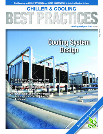
Cooling towers differ from closed circuit coolers in that closed-circuit coolers reject heatsensibly while cooling towers reject heat latently. Consider ambient design conditions of95 F DB and 78 F wb. If closed circuit coolers are used, the condenser water must bewarmer than the ambient dry bulb (typically 10 F warmer or 105 F). This raises thecondensing pressure in the chiller and requires more overall power for cooling. Closedcircuit coolers are larger than cooling towers for the same capacity and can be difficult tolocate on the roof.Cooling towers expose the condenser water directly to the ambient air in a process thatresembles a waterfall. Approximately 1% of the design condenser water flow isevaporated. The latent energy required to evaporate the water lowers the remaining waterssensible temperature. The process is based on the ambient wet bulb temperature (78 F wbin the example) rather than the dry bulb temperature. ARI standard conditions at full loadare based on 85 F entering condenser water temperature and 3.0 US gpm per ton. Lowercondenser water temperatures can be produced in many climates with low wet bulbtemperatures.LoadsFigure 4, Air Handling EquipmentChilled water coils are used to transfer the heat from the building air to the chilled water.The coils can be located in air handling units, fan coils, induction units, etc. The air is cooledand dehumidified as it passes through the coils. The chilled water temperature rises duringthe process.Process loads can reject heat in the chilled water in a variety of ways. A common processload is a cooling jacket in machinery such as injection molding equipment. Here the chilledwater absorbs the sensible heat of the process.ControlsThere are two parameters that need to be considered for the chilled water loop. These aretemperature and flow. The loop supply temperature is controlled at the chiller. The unitcontroller on the chiller will monitor and maintain the supply chilled water temperature(within it’s capacity range). The accuracy to which the chiller can maintain the set point isbased on the chiller type, controller quality (a DDC controller with a PID loop is the best),compressor cycle times, the volume of fluid in the system, etc. Systems with fast changingloads (especially process loads) and small fluid volumes (close coupled) require specialconsideration.6Application Guide AG 31-003
Figure 5, Chiller ControllerThe system flow control occurs at the load. To maintain the correct space condition, threeway or two-way control valves are used. Three-way control valves direct chilled watereither through or around the coil to maintain the desired condition. If all the loads on the loopuse three-way valves then the chilled water flow is constant. The temperature range variesdirectly with the load. That is, if the design chilled water Delta-T is 10 F, then every 10%drop in system load represents 1 F drop in Delta-T.Figure 6, Three-way ValvesApplication Guide AG 31-0037
DiversityA system incorporating three-way control valves is easy to design and operate. However,the system pumps all the water all the time, which requires more pump horsepower. In mostcases the chiller is sized for the building peak load. Due to diversity, not all the connectedloads will “peak” at the same time as the building peak load. However, the pumps and pipingsystem must be designed for full flow to all the control valves all the time. Since the chillerflow rate is the same as the flow rate through all the loads (they’re connected by the chillerDelta-T.For example, consider a building with an 80-ton peak load. However, summing all theconnected loads adds up to 100 tons. In short, this building has a diversity of 80%. Using adelta of 10 F at each control valve, the total system flow rate is;Flow 24 x 100 tons/10 F 240 gpmHowever, an 80-ton chiller with 240 gpm will only have a Delta-T of 8 F. The lower chillerDelta-T is not a problem for the chiller operation, but it will lower the chiller efficiency. Caremust be taken to select the chiller at the proper Delta-T.Figure 7, Two-way ValvesWhen two-way modulating control valves are used, the flow to the coil is restricted ratherthan bypassed. If all the valves in the system are two-way type, the flow will vary with theload. If the valves are properly selected, the temperature range remains constant and theflow varies directly with the load. In this case the diversity is applied to the chilled waterflow rate.Using the previous example, the peak load is 80 tons and the design flow is 2.4 x 80 tons or192 gpm. The connected load is still 100 tons and requires 240 gpm if all the two-way8Application Guide AG 31-003
control valves are open at the same time. The 80% diversity assumes only 80% of thevalves will be open at the peak load.The advantage of two-way control valves is both the pump and the piping are sized for asmaller flow rate offering both first cost and operating savings. The difficulty is the chillerand control system must be designed for variable flow. The chiller has a minimum flow rateso the piping design has to allow for enough flow during all operating conditions to meet thechiller minimum flow rate. Using two-way valves at the loads is the main building block fora variable flow system.Parallel ChillersFigure 8, Parallel ChillersTo provide some redundancy in theHVAC design, most designers willrequire two or more chillers. Multiplechillers also offer the opportunity toimprove on overall system part loadperformance and reduce energyconsumption.Figure 8 shows two chillers in paralleland three-way valves at the loads. Thechilled water temperature differencevaries directly with the load. The othersystem components are the same as theprevious example. The difficulty withthis parallel arrangement is the systempart load performance.Consider the system operating at 50%. From a chiller performance aspect, turning off onechiller and operating the other at full capacity is desirable. However, this will not happen.At 50% capacity, the return water will be 49 F. The chiller that is turned off, will let thewater pass through it unchanged. The operating chiller will only see a 50% load (49 F returnwater), and will cool the water down to the set point of 44 F. The two chilled water streamswill then mix to 46.5 F supply temperature.If the system is operated in this manner, the warmer chilled water will cause the controlvalves to open (increase flow) to meet the space requirements. The return watertemperature will rise affecting the supply system supply water temperature. An iterativeprocess will occur and the system can stabilize. The issue is whether the cooling coils canmeet the local loads with the higher chilled water temperature. Depending on the actualdesign conditions, the building sensible load could be met but high chilled water temperaturewill make it difficult to meet the latent load. Since this scenario is likely to occur duringshoulder weather, dehumidification can not be an issue. In areas where humidity is an issue,this arrangement will result in high humidity within the space.One solution is to operate both chillers all the time. This works and is a simple solution,however, it is not energy efficient and causes unnecessary equipment wear.Another possibility is to lower the operating chiller’s set point to offset the mixed watertemperature. This too works but has some difficulties. Lowering the chilled water set pointApplication Guide AG 31-0039
requires the chiller to work harder lowering its efficiency. In extreme conditions, it cancause chiller stability issues.Figure 9, Parallel Chillers with Isolating ValvesFigure 9 shows a modified version ofparallel chillers. This concept incorporatesisolating valves for each chiller. Thechilled water pump includes a VariableFrequency Drive (VFD). The loads nowhave two-way valves.In this design concept, as the system loaddecreases, the flow is reduced until one ofthe chillers can be shut down and itsisolating valve is closed. Supply watertemperature remains constant.This design requires careful chillerselectiontoprovidegoodflowcharacteristics over the required operatingrange. More sophisticated controls are required to operate the system. See Variable FlowDesign for further details.Series ChillersFigure 10, Series ChillersFigure 10 shows twochillers in series.Thisdesign concept resolves themixed flow issues found inparallel chiller designs. Itis simple to design andoperate. However, it alsohas some challenges toovercome.All the system flow goesthrough both chillers. Ifboth chillers are the sameand the condensers arepiped in parallel, the leadchiller will accomplishabout 45% of the system load and the lag chiller will accomplish about 55% of the systemload. This occurs because the lead chiller is supplying chiller water at the system set point(typically 44 F). The lag chiller is supplying chilled water at approximately 48.5 F to the leadchiller. The reduced lift for the lag chiller allows it to provide more cooling capacity.A problem with series chillers is the high flow rate and the low Delta T through the chillers.The high flow rate can result in high water pressure drops. Since the chillers are in series,the pressure drops of the chillers must be added. If the typical 10 F system temperature10Application Guide AG 31-003
difference is maintained, then single pass evaporators should be considered. This will lowerthe pressure drop to an acceptable level.There is an opportunity to optimize series chillers and improve overall system performanceby connecting the condensers in series as well. Figure 10 shows the condensers connectedin series with the condenser flow counter flow to the chilled water flow.Table 1, System Efficiency ComparisonCHILLER VESSELPIPINGPARALLEL CH-1PARALLEL CH-2SYSTEM TOTALSERIES OPT 1 CH-1SERIES OPT 1 CH-2SYSTEM TOTALSERIES OPT 2 CH-1SEREIS OPT 2 CH-2SYSTEM TOTALCAP(tons)400400800440370810440370810EVAPEWT( F)5454545448.5545448.554EVAPLWT( 019201920192019201920CONDEWT( F)85858585858589.18585CONDLWT( .5470.5470.5200.5560.5360.5290.5230.526Table 1 compares a parallel system with two versions of series systems for an 800 tondesign load. The full load penalty for series option 1 compared to the parallel system isnegligible. Series Option 2 shows chillers with series condenser flow. It provides the bestoverall system performance and either chiller can be the lead chiller. Series condensers andseries evaporators are an excellent means to provide lower temperature, high Delta-T chilledwater.It should not be concluded that parallel systems have no value. In applications where mostof the operating hours occur above 50% load, a parallel system typically does better. Aseries system does better when there lots of run hours below 50% such as an HVAC systemwithout air side economizers.Series Chillers ControlsAs before, the chiller controllers maintain the system supply water temperature and the loadcontrols maintain the system flow rate. For series chillers, the controlling sensors for bothchillers should be located downstream of the chillers and the chiller control panels digitallylinked together. With the panels linked together, either chiller can be used to meet up toabout 45% of the system load. Once both chillers are required, the amp draws can bebalanced between the two chillers.The MicroTech Controllers on McQuay chillers can communicate directly and can loadbalance based on amperage. Using the load balance feature means when both chillersoperate, the power consumption is evenly distributed between the two chillers. The loadbalance feature offers about 3% savings conventional control.Primary/Secondary SystemsFor large chillers or where more than 2 chillers are anticipated, primary/secondary (alsocalled decoupled) piping systems are used. To reduce installation and operating costs, it isdesirable to apply diversity to system flow. With diversity applied to flow, the pumps andpiping will be smaller. To accomplish this, two-way control valves are used at the loads. Atthe same time it is necessary to provide constant flow through the chillers to maintain chillerstability. The solution is primary/secondary piping.Application Guide AG 31-00311
Figure 11, Primary/Secondary Loop at Full LoadSECONDARY PUMPVFDPRIMARY PUMP1920 gpm1920 gpm44 FC H ILL ER44 F44 FA800 TONS0 gpmLOAD800 TONS(DECOUPLER)COMMONPIPE54 FB54 F54 F1920 gpm1920 gpmPrimary/Secondary Loop BasicsFigure 11 shows a basic primary/secondary loop operating at full load. In this example, thesystem design load is 800 tons, the flow rates and temperatures are at standard ARIconditions and the load has a two-way control valve. The loop with the chiller is called theprimary loop. The loop with the load is the secondary loop. The common pipe is sometimesreferred to as the decoupler.At full load, the design flow of 1920 gpm passes through the chiller, the two pumps, the load,and back to the chiller. There is no flow through the common pipe. At first, it would appearthat the flow is being pumped twice. Although this is true, the total head is split between thetwo pumps. The primary pump is only sized for the primary loop of which the chiller is mainpressure drop. The secondary pump is sized for the pressure drop “outside the mechanicalroom”. The higher pressure drops and larger piping arrangements in the secondary loopjustify the variable flow.Figure 12, Primary/Secondary Loop at 50% LoadSECONDARY PUMPVFDPRIMARY PUMP1920 gpm960 gpm44 FCHILL ER44 F1920 gpm44 F400 TONS49 F12A960 gpm(DECOUPLER)COMMONPIPELOAD400 TONS54 FB49 F1920 gpm960 gpm54 FApplication Guide AG 31-003
Figure 12 shows the same example operating at 50% capacity. The two-way control valveat the load has reduced the flow in the secondary loop to 960 gpm. The Delta-T across theload remains at 10 F. The primary pump is a constant flow pump sized for the chiller designflow. It remains constant at 1920 gpm. The additional flow not required in the secondaryloop passes through the common pipe to the chiller return line. The 44 F fluid from thecommon pipe mixes with the 54 F return fluid to 49 F. The chiller maintains its design flowof 1920 gpm with 49 F RWT and 44 F LWT. The chiller sees a 50% load.The example in Figure 12 demonstrates how diversity is applied to flow in the secondaryloop. The variable flow in the secondary loop offers excellent pump operating savings andfirst cost saving in pipe sizing. The constant flow in the primary loop provides the chiller withstable operating conditions.Figure 13, Primary/Secondary Loop at Low Delta-TSECONDARY PUMPVFDPRIMARY PUMP1920 gpm3200 gpmCHILLER44 F44 F1920 gpm44 FA480 TONS(DECOUPLER)COMMONPIPE1280 gpm50 FLOAD800 TONS50 FB1920 gpm50 F3200 gpm50 FIt is important to understand what happens if design temperature range is not maintained.This is known as a low Delta-T syndrome. Figure 13 shows the previous example with an800 ton load but only a 6 F Delta-T. This could be caused by several factors including poorvalve selection or dirty coils.To meet the 800-ton load requirement, the control valve will respond by opening and allowingmore flow through the load. The secondary pump will respond in turn by increasing thesecondary loop flow to 3200 gpm to meet the load. The primary pump is only supplying 1920gpm so 1280 gpm will flow “backward” through the common pipe to meet the 3200 gpmrequirement. Two problems now occur. The supply fluid temperature in the secondary loopwill rise when the primary fluid and the return fluid mix. The higher fluid temperature willcause the control valve to open further, making the problem worse. The second problem isthe return water to the chiller is only 50 F so the chiller only sees a 480-ton load. Thissystem will not function well under these conditions.Application Guide AG 31-00313
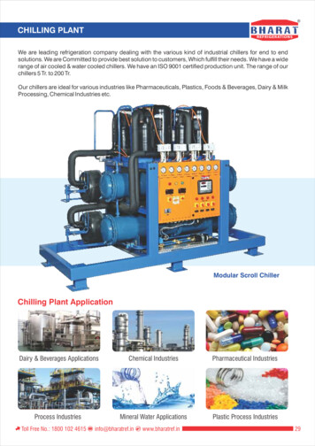
Figure 14, Primary/Secondary Loop with Low Delta-T RealitySECONDARY PUMPVFDPRIMARY PUMP1920 gpmPRIMARY PUMP1920 gpm400TONS49 F44 FCHILLERCHILLER44 F3200 gpm44 F3840 gpm44 F400TONS49 FA640 gpm44 F(DECOUPLER)COMMONPIPELOAD800 TONS50 FB3840 gpm49 F3200 gpm50 FObviously the above example can’t occur. Figure 14 shows what does happen. A secondchiller has to be started to balance the flow in the primary loop with the flow in thesecondary loop.Although running two chillers provides a working solution, many of the features of theprimary/secondary approach are lost. The flow in the secondary is high, wasting pumpingenergy. Two primary pumps have to operate when only one should be doubling the primarypump horsepower. Finally, two chillers are operating (and their condenser water pumps)when only one should be.Primary Loop DetailsFigure 15, Standard Primary Loop LayoutThe most common arrangementis to have dedicated pumps foreach chiller. In addition, eachchiller requires an isolating valve.It is also possible to have a mainprimary pump outfitted either withmultiple speeds or a variablefrequency drive. The issue withthe latter is there is minimal to noredundancy available.The chillers can have differentcapacities and be manufacturedby different vendors. However,they must have the same supplywater set point and the samechilled water Delta-T.14Application Guide AG 31-003
Decoupler LocationThe location of the decoupler line will change how the chillers are loaded. Figure 15 showsthe typical layout. In this situation, each chiller sees the same return water temperature evenat part load conditions.Figure 16 shows the decoupler line in a different location. Locating the chillers between thesecondary loop and the decoupler line causes the return water temperature to each chiller tovary. Chiller 2 in Figure 16 will see close to the secondary loop return water temperature.Chiller 1 will see a mixture of supply water and return water. The result is Chiller 2 is moreheavily loaded than Chiller 1.Figure 16, Optional Primary Loop LayoutRelocating the decoupler can make sense if one or more of the chillers is a dual compressormodel. The dual compressor chiller has very good part load performance. Singlecompressor chillers typically work best when fully loaded. By locating the dual compressorchiller close to the decoupler line and the single compressor chiller furthest away, thestrengths of each chiller can be maximized. Table 2 shows the chiller plant performance forFigures 15 and 16. By base loading the single compressor chiller and taking advantage ofthe dual’s part load performance, the power input can be cut by up to 10 percent.Application Guide AG 31-00315
Table 2, Table 2 Chiller Plant Performance vs. Decoupler LocationFigure 15CH-1CH-2TotalFigure 16CH-1CH-2TotalCap. (tons)300300600RWT ( F)51.551.551.5SWT ( F)444444Power .9Secondary Loop DetailsFigure 17, Basic Secondary LoopThe secondary loop must be variable flow.Traditionally, multiple pumps were staged on to varythe flow. More recently, variable frequency drivesare used. The primary/secondary arrangementallows the engineer a great deal of flexibility whendesigning the distribution piping. Figure 17 shows thebasic design. Multiple secondary pumps are used toprovide some redundancy.Figure 18, Multiple Secondary LoopsFigure 18 shows dedicated pumps for various loops.Multiple loops can serve areas with differentoperating schedules or widely different fluidpressure drops (such as a building on the far side ofa campus). The individual loops can be scheduledoff when not required.Controlling the secondary pumps is a subject ofsome debate. Most systems today use somemethod of pressure differential across thesecondary loop. The location for the pressuresensors is critical. Proper system operation requiresthat the load control valves be properly sized andthe pressure sensors properly located. This is adiscussion in itself and is beyond the scope of this manual.16Application Guide AG 31-003
Reverse Return/Direct Return PipingThe examples used in this manual show reverse return piping. The secondary piping isdesigned such that any path through any load is the same length and therefore hasapproximately the same fluid pressure drop. Reverse return piping is inherently selfbalancing. It also requires more piping and consequently is more expensive.Direct return piping results in the load closest to the chiller plant to have the shortest pathand therefore the lowest fluid pressure drop. Depending on the piping design, the differencein pressure drops between a load near the chiller plant and a load at the end of the piping runcan be substantial. Balancing the system can be difficult. The advantage of direct returnpiping is the pipe savings.The decision whether to use direct or reverse return piping should be based on systemoperability vs. first cost. Where direct return piping is used, flow-balancing valves should becare
Figure 4 , Air Handling Equipment Chilled water coils are used to transfer the heat from the building air to the chilled water. The coils can be located in air handling units, fan coils, induction units, etc. The air is cooled and dehumidified as it passes through the coils. The chilled water temperature rises during the process.