Transcription
Chiller Systemsfor Combustion Inlet Air CoolingTrevor RichterVice President, Stellar Energy Systems, Inc.Presented atASME Turbo ExpoVancouver, BC, CanadaJune 6-10, 20111
Chiller SystemsOutline Drivers for Chiller Systems TIAC Chiller System Overview Predominant Chiller System Types Project Design Parameters System Design Considerations Summary2
Chiller SystemsDrivers Additional Output Dispatch Priority Predictable and Consistent Output Altitude Compensation Matching Output of Competitors GT Waste Heat Utilization3
Chiller SystemsTIAC Chiller System Overview4
Chiller SystemsPredominant Types Electric Centrifugal Chillers Screw Compressor Refrigeration Systems Absorption Chillers5
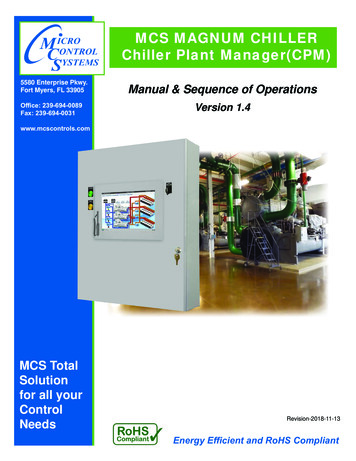
Chiller SystemsElectric Centrifugal Chillers withCooling TowersBenefitsLimitations High Efficiency Requires MakeupWater Low Cost Small Footprint Operational Flexibility Open Loop HeatRejection Water Discharge6
Chiller SystemsElectric Centrifugal Chillers withCooling Towers7
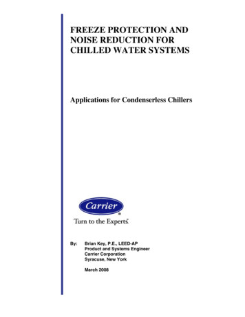
Chiller SystemsElectric Centrifugal Chillers withRadiatorsBenefitsLimitations No Water Required Lower Efficiency thanwith Cooling Towers Relatively Fast Startup Low Cost Air-CooledSystem Larger Footprint Higher Sound Levels Higher Cost than withCooling Towers8
Chiller SystemsElectric Centrifugal Chillers withRadiators9
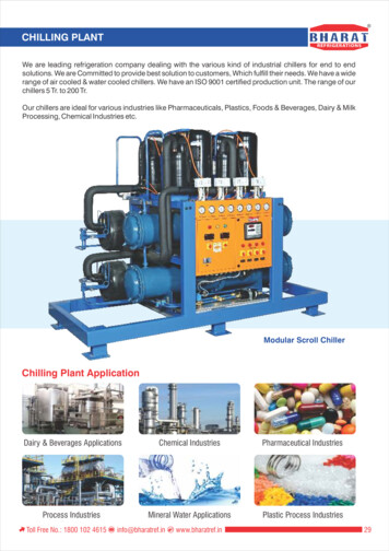
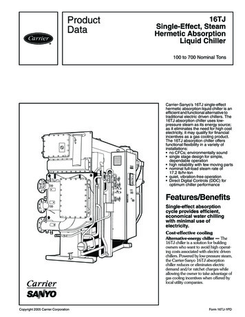
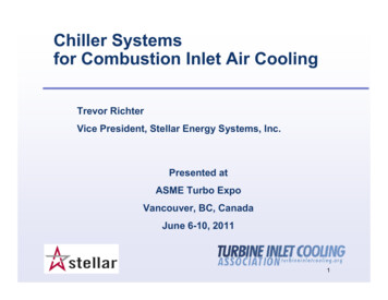
Chiller SystemsScrew Compressor RefrigerationSystem with Air-Cooled CondenserBenefitsLimitations No Water Required Lower Efficiency Relatively Fast Startup Larger Footprint Can be Modular Higher Sound Levels Higher Cost10
Chiller SystemsScrew Compressor RefrigerationSystem with Air-Cooled Condenser11
Chiller SystemsAbsorption Chiller with CoolingTowersBenefitsLimitations Fueled by Heat orNatural Gas Supply Water Temps Makeup Water Req Higher Cost Lacks Flexibility Must use Heat whenAvailable12
Chiller SystemsAbsorption Chiller with CoolingTowers13
Chiller SystemsProject Design Parameters - Sizing Ambient Design Conditions Elevation (Inlet Pressure) Mass Flow (Inlet Temperature) Parasitic Losses Pipe Heat Leak Pump Heat Load Chiller Plant Cooling Auxiliary Loads14
Chiller SystemsProject Design Parameters - IAT Maximum Output Optimal Capital Optimum Heat Rate Minimum Augmentation Satisfy Capacity Contract Satisfy Competitive Specification Site Utility Limitation15
Chiller SystemsProject Design Parameters - Site Equipment Space Chiller Plant Energy Source Heat Rejection Permitting16
Chiller SystemsSystem Design ConsiderationsHeat Transfer for Inlet Air Face Velocity (400 to 500 fpm) Pressure Drop Size Limitations Supply Temperature (Direct vs TES) Freeze Protection Macro-Environments17
Chiller SystemsSystem Design ConsiderationsChiller Type Refrigerant Configuration Tube Material Manufacturer18
Chiller SystemsSystem Design ConsiderationsPump Redundancy Configuration Motors19
Chiller SystemsSystem Design ConsiderationsHeat Rejection Cooling Towers Materials Sound Natural Radiators Condensers (wet surface or air-cooled)20
Chiller SystemsSystem Design ConsiderationsElectrical Feeds Standards (NEMA,IEC, etc.) Gear (Arc Flash Resistant) Motors Controls21
Chiller SystemsSummary Output Independent of Ambient Conditions Water Consumption and Discharge Design Parameter Determination is Key22
Can be Modular Chiller Systems Screw Compressor Refrigeration System with Air-Cooled Condenser Limitations . Chiller Plant Cooling Auxiliary Loads Chiller Systems Project Design Parameters - Sizing. 15