Transcription
May 2016The Magazine for ENERGY EFFICIENCY and WATER CONSERVATION in Industrial Cooling SystemsCooling SystemDesign10 Eliminating Catalyst Cool Downas Critical Path in a Turnaround22 Evaluating Chilled Water CoolingSystem Components26 Tower Tech Cooling Tower Designs16CHI2HOkWLLERSAT2016AHREXPOReduce Water Consumption andTreatmentCO2
Free Expo Passwww.energyevent.com/FreeExpoPassMay 25-26, 2016Washington State Convention CenterSeattle, WashingtonEXPOpresented byhosted byCONFERENCESEMINARSplatinum sponsorsilver nze sponsors
SUSTAINABLE MANUFACTURING FEATURESM A Y2 0 1 6 V O L U M E2 ,N O .2 SUSTAINABLE MANUFACTURING FEATURES4From the Editor5Chiller & Cooling System Industry News10Eliminating Catalyst Cool Down as CriticalPath in a TurnaroundBy Barney Smith, Turnaround Manager, Aggreko1616SHOW REPORTChillers and Cooling Towers at 2016 AHR EXPOBy Roderick Smith, Chiller & Cooling Best Practices Magazine22Evaluating Chilled Water Cooling SystemComponentsBy Joe Leichner, Daikin Applied Americas2226Tower Tech Cooling Tower Designs ReduceWater Consumption and TreatmentBy Dr. S. Curtis, Ph.D., Tower Tech, Inc.30SHOW REPORTProcess Chillers at Process ExpoBy Roderick Smith, Chiller & Cooling Best Practices Magazine34THE MARKETPLACEJobs and Technology26coolingbestpractices.com3
SUSTAINABLE MANUFACTURING FEATURES0 5 / 1 6FROM THE EDITORCooling System DesignIndustrial cooling requirements, in a single plant, are as diverse as theyare critical to ensure product and process quality. These two factorsmake cooling system design requirements unique to each plant and a realengineering challenge.EDITORIAL ADVISORY BOARDThe 2016 AHR Expo provided a spectacular display of chiller, cooling tower, refrigerationcompressors and circuits and measurement technologies. Serving industrial and commercial usersand the specifying engineering firms, this industry is innovating like crazy to meet market demandsfor lower water and energy consumption as well as new greenhouse gas regulations. I hope youenjoy our Show Report on the booths I was able to visit.Daikin Applied is one of the largest chiller manufacturers in the world. Their Director of Operationsand Owner Sales, Joe Leichner writes, “While the chiller is the heart of a chilled water system, itssupport system of components and controls are equally critical to attain high efficiency levels.” Hisarticle titled, “Evaluating Chilled Water Cooling System Components,” reviews water pumps, coolingtowers, heat exchangers, controls and hydronic specialty components.Tower Tech is a cooling tower manufacturer based in Oklahoma City. They have provided us withan interesting article on how tower designs can impact water consumption rates and also chemicaltreatment requirements. For example, outside environmental factors, such as wind-blown sediments,can impact a system’s oxidizer demand, therefore requiring more chlorine to maintain a sufficientlyhigh level of residual. A cooling tower can be designed to reduce outside environmental factors.Lastly, we hope you enjoy my rather belated Show Report on chiller technologies at Process Expo.Previewing a couple snippets from the article, Dimplex Thermal Solutions described their 90-tonKoolant Kooler unit at Arcadia Brewing, Berg reviewed the cooling requirements of ice-makingmachines, Thermal Care described their 20-ton wash-down chiller, and Mokon described theirFull Range unit able to offer both process heating and chilling in one package – to an extruderrequiring water temperature control in 7 different zones. Seven zones in just one machine – talkabout diverse requirements!Thank you for investing your time and knowledge with Chiller & Cooling Best Practices and pleaseremember to visit www.coolingbestpractices.com.ROD SMITHEditortel: 412-980-9901, rod@airbestpractices.com, www.coolingbestpractices.com2016 MEDIA PARTNERS4coolingbestpractices.comIndustrial Energy ManagersOur lead article, “Eliminating Catalyst Cool Down as Critical Path in aTurnaround,” provides an example of the critical nature of cooling systemsin refineries and petrochemical plants. Written by Aggreko’s Turnaround Manager, BarneySmith, this article proposes replacing liquid nitrogen with a patented process (using a water/glycol solution in a heat exchanger) during the catalyst cool-down processes in hydrotreaters,hydrocrackers and reformers.Doug BarndtManager, Demand Side BallEnergy-SustainabilityCorporationRichard FeustelSenior Energy AdvisorLeidosWilliam JeraldEnergy ManagerCalPortlandJennifer MeierGlobal EH&S/Plant EngineeringManagerVarroc LightingSystemsThomas MortChief Operating OfficerMission PointEnergyBrad ReedCorporate Energy TeamToyotaLeaderBrad RundaGlobal Director, EnergyKochIndustriesUli SchildtEnergy EngineerDarigoldDon SturtevantCorporate EnergyManagerSimplotThomas SullivanEnergy PerformanceManagerMichelin NorthAmericaBryan WhitfieldSr. Solutions EngineerEnerNOC
SUSTAINABLE MANUFACTURING FEATURES0 5 / 1 6 CHILLER & COOLING SYSTEM INDUSTRY NEWSAggreko Replacement Chiller Restartsa Chemical Plant Within 12 HoursA Gulf Coast chemical manufacturer of oxoderivative and intermediate products includingalcohols, polyols, carboxylic acids, specialtyesters, and amines experienced a failure in acritical chiller that shut down its entire GulfCoast plant.A plant manager estimated a potential financialloss of over 1,000,000 each day the plant wasdown. The incident occurred over the weekendand there was great concern that locating areplacement chiller with sufficient capacitywould be challenging.Third-party temperature control providerAggreko deployed a replacement chillerand had it running along with a 1500kWgenerator within a day. It was originallyexpected that the temporary chiller would benecessary for only a few days until the plant’spermanent chiller could be fixed. However,after inspection the plant learned it wouldtake over a month to complete its repairs.Due to this longer time interval, the Aggrekogenerator was scheduled to be taken downfor quick maintenance within two weeks.However, twelve days into the rental, AggrekoRemote Monitoring (ARM), a service thatmonitors and transmits critical informationabout Aggreko’s rental equipment, sent analert to the Remote Operating Center (ROC)that the generator was running, but there wasno load. This seemed unusual to the Aggrekotechnicians who immediately contacted theplant to assess onsite activity.Aggreko was informed the plant hadexperienced an electrical emergency forcingthem to fix its switchgear, thus Aggreko utilizedthis time and quickly mobilized a crew to theplant where they performed the necessarygenerator maintenance. This quick actionaverted another shutdown. Aggreko’s quickaction both right after the initial chiller failureand during the unexpected switchgear issue,literally saved the client millions of dollars.Visit www.aggreko.com.“Aggreko’s quick action both right after the initial chiller failure and during”the unexpected switchgear issue, literally saved the client millions of dollars.coolingbestpractices.com5
SUSTAINABLE MANUFACTURING FEATURES0 5 / 1 6CHILLER & COOLING SYSTEM INDUSTRY NEWSJohnson Controls Expands YORKYMC2 Centrifugal Chiller LineJohnson Controls has enhanced its’ portfolioof commercial HVAC/R products with theexpansion to 1,000 tons of cooling (3,500kW) for its successful magnetic-bearingcentrifugal chiller line, the YORK YMC2. Thelarger cooling capacity units address the needfor reduced sound, high efficiency and lowmaintenance while advancing the future ofchillers through magnetic bearing and oil freetechnology.The chiller uses magnetic levitationtechnology in its driveline to spin withoutfriction, offering a quieter, more efficientoperation. The YMC2 also has a standardvariable speed drive to further increase theefficiency of the chiller.pp Sound levels as low as70 dBA for quiet operationpp YORK chillers are knownfor utilizing industry-leadinglow entering condenserwater temperature to reduceenergy usage. The YMC2chiller is capable of achieving6coolingbestpractices.comvalues below 0.1 kW/tonat part load, resulting in asignificantly lower utility bill.pp The oil-free design deliversreliable operation and lowmaintenance, providing alower total cost of ownershipover the life of the chiller.“The YMC2 chiller is an example of JohnsonControls' ability to develop innovative solutionsto solve our customers' challenges,” saidLaura Wand, vice president of global chillers,Johnson Controls Building Efficiency Business.“In addition to the YMC2 chiller, our newofferings include a lower-cost air-cooledchiller and smart, connected chiller technologythat supports optimized uptime. We have theindustry's best and most extensive productportfolio, and we intend to build on it toenhance our offerings to a diverse customerbase around the world.” The complete YMC2line now offers units from 165 – 1,000 tons(580 kW to 3,500 kW).Visit http://www.johnsoncontrols.com or follow us @johnsoncontrolson Twitter.Emerson Launches New CopelandScroll Variable Speed CompressorEmerson Climate Technologies, Inc., haslaunched the second generation of its CopelandScroll variable speed ZPV2 compressor andEV2 motor control drive for residential and lightcommercial applications.“Our second generation, variable speed ZPV2compressors and EV2 drives are optimized toincrease efficiency across a range of conditionswhile maintaining the reliability that CopelandScroll technology traditionally delivers,”said Brandy Powell, vice president variablespeed at Emerson Climate Technologies AirConditioning Business.The second generation Copeland Scroll variablespeed ZPV2 compressor features intermediatedischarge valves to boost efficiency, optimizedscroll elements for variable speed performance,positive displacement oil pump for enhancedreliability in low speed operation and brushlesspermanent magnet (BPM) motor technologyfor maximum efficiency.Integrated CoreSense technology is built intothe new Copeland Scroll variable speed EV2
SUSTAINABLE MANUFACTURING FEATURES0 5 / 1 6 motor control drive for optimal compressorperformance. Features include soft startingcapability, controlled shutdown, scroll overtemperature protection and high pressurecutout. In addition, the drive protects thecompressor from operating outside of thedesign parameters and against electricalpower variations.The new Copeland Scroll variable speedcompressors and motor control drives canenable system manufacturers to achieveindustry leading 25 Seasonal EnergyEfficiency Ratio (SEER) and 13 HeatingSeasonal Performance Factor (HSPF).Homeowners and small businesses haveexperienced greater comfort and annualenergy savings of up to 40% with HVACsystems featuring Copeland Scroll variablespeed compressors.The N-Series Chiller features accessiblecomponents and appropriate fin spacing toallow for easy maintenance, and is designedto be serviceable with a minimal numberof OEM components. Additionally, CenturyRefrigeration’s expert service techniciansand large inventory of replacement partsensures timely, professional, and reliableservice throughout the chiller’s lifetime.Visit www.RAECorp.comVisit EmersonClimate.com.Century RefrigerationIntroduces N-Series ChillersCentury Refrigeration, a division of RAECorporation, an industry leader in the designand production of engineered heating, cooling,and refrigeration systems, announced theavailability of its N-Series Chillers. The N-SeriesChiller provides all the advantages of a provenCentury Comdustrial design in a complete,factory run-tested chiller package engineeredfor durability and serviceability.With a variety of available options andaccessories, Century Refrigeration’s engineeringexperts can design and build N-Series Chillerunits for a range of chilling applications withno need for modification in the field. TheN-Series Chiller is constructed from high-qualitycomponents for the greatest possible durability,thereby optimizing efficiency and lengtheningservice life.coolingbestpractices.com7
SUSTAINABLE MANUFACTURING FEATURES0 5 / 1 6CHILLER & COOLING SYSTEM INDUSTRY NEWSBaltimore Aircoil CompanyRecognized at 2016 AHR ExpoBaltimore Aircoil Company (BAC) wasrecognized with a record three honorablementions in the 2016 AHR Expo InnovationAward categories of Cooling, Green Building,and Refrigeration. Don Fetzer BAC’s Presidentemphasized, “We’re pleased to be recognizedfor our investment in innovation andtechnology and for leading the evaporativecooling industry into the future.”In the Cooling category, the New Series3000 Cooling Tower continues its industryleadership winning an honorable mention.Coupled with the ENDURADRIVE Fan System,the New Series 3000 is the only direct drivesolution that eliminates powertrain systems inlarge capacity cooling towers. This fan systemprovides unmatched reliability, superiorenergy savings, and the lowest maintenancecosts in the industry. The Series 3000 withthe ENDURADRIVE Fan System now offers thelargest single cell modular cooling tower inthe world with 1,446 nominal tons! AdditionalENDURADRIVE Fan System benefits includea “10% reduction in energy costs with notransmission or mechanical losses, significantenergy savings, and a 90% reduction inmaintenance costs compared to a traditionalgear drive system,” Fetzer explained.In the Green Building category, the PFi ClosedCircuit Cooling Tower won honorable mentionby offering customers the combination ofdirect and indirect heat transfer enhancingthermal efficiency by 30% or more. Thisengineered concept increases performancewhile enhancing the unit’s reliability foryear-round operation. The PFi has thelowest installed cost compared to other8coolingbestpractices.comcounterflow closed circuit cooling towers dueto a combination of the lowest weight, fanhorsepower, and smallest footprint. It alsofeatures the lowest total cost of ownershipwith Extreme Efficiency models (XE Models)that reduce operating costs by up to 50%.This is all with the peace of mind that eachPFi is CTI Certified for water and glycol forguaranteed performance. Fetzer added,“We’re pleased to have been recognized forthe engineering and design innovation thatcontributed to the development of this newtechnology.”Bitzer Approves HFO Refrigerantsfor Screw CompressorsLastly, in the Refrigeration category theTrilliumSeries Condenser for TranscriticalCO2 Applications received honorable mention.With higher performance and lower operatingcosts, water cooled methods offer the bestlong-term investment for any cooling system.Systems with adiabatic heat rejection, such asthe hybrid TrilliumSeries Condenser, operatewith efficiencies mid-way between air andwater cooled methods. The TrilliumSeriesCondenser uses water only on the hottestdays to maintain condensing temperatures,attaining up to 38% energy cost savingscompared to air cooled technology. Withits low water use profile, the TrilliumSeriesCondenser is a proven solution when wateris scarce. Furthermore, to address regulatoryconcerns associated with traditionalrefrigerants, the unique adiabatic design ofthe TrilliumSeries Condenser empowers thedesign and application of transcritical CO2refrigeration systems to virtually all climatezones worldwide. “We’re excited to lead theindustry with sustainable solutions that allowfor more natural refrigerants,” Fetzer added.The requirements stipulated by the EU’s F-gasRegulation no. 517/2014 also represent a hugechallenge for manufacturers of refrigerationcompressors. In order to meet the phasedown objectives, alternative refrigerantssuch as hydrofluoroolefins (HFOs) will haveto be used in the future. The volumetricrefrigerating capacity and pressure levels ofR1234yf are comparable with those of R134a,while the capacity figures and pressure levelsof R1234ze(E) are around 20 to 25% lower.BITZER subjected the R1234yf and R1234ze(E)refrigerants in this group to intensive testing,and the compressors performed well with bothin all of the tests and laboratory experiments.The tested compressors achieved nearlyidentical isentropic efficiency values withR1234yf and R1234ze(E) as with R134a. Dueto differences in the thermodynamic properties,the COP measurement results are in some casesslightly lower.Visit www.baltimoreaircoil.comFollowing an extensive qualification program,compressor specialist BITZER has announcedapproval of the R1234yf and R1234ze(E)HFO refrigerants for its CSH and CSW screwcompressors. The two alternatives to R134ahave a global warming potential (GWP) of underten, while the GWP of R134a is around 1,400.With a GWP of about 600 each, the HFO/HFCblends R513A and R450A are also approvedfor the CSH and CSW series. Unlike the pureHFO refrigerants, they’re nonflammable.Both of the HFOs are suitable for airconditioning and medium temperatureapplications in particular, as well as for heatpumps. There’s often a degree of uncertaintyregarding flammability. In safety data sheets,
SUSTAINABLE MANUFACTURING FEATURESR1234ze(E) is listed as nonflammable, thoughthis only applies to transport and storage.When used as a refrigerant, a higher referencetemperature of 60 C is applied in flammabilitytests. At this temperature, R1234ze(E) isflammable and therefore assigned to the A2Lsafety group, just like R1234yf. For this reason,a risk assessment in accordance with the ATEXDirective is required for systems with bothrefrigerants – with potential consequences inthe system design. BITZER compressors forHFO refrigerant fulfill the relevant requirements,making additional evaluation unnecessary.HFO/HFC blends such as R513A and R450A, onthe other hand, are nonflammable and thereforeclassified in the A1 safety group. Using themrequires nothing more than a conventional riskassessment in accordance with the MachineryDirective. However, the substitutes R513A andR450A have a GWP of around 600.After evaluating all of the results, BITZER hasannounced approval of the HFO refrigerantsR1234yf and R1234ze(E) and the HFO/HFC blends for CSH and CSW compact screwcompressors. These tried-and-tested productscan be operated with the standard ester oilcharge (Y-model) with HFO refrigerants in thedocumented applications.0 5 / 1 6 Detailed technical descriptions with performancedata and application limits can be found inthe SP-171-3 (CSH) and SP-172-6 (CSW)documentation. The corresponding data will beprovided in the BITZER software in due time.CSH and CSW: high energy efficiencyThe universal CSH and CSW compact screwcompressors can also be used with theeconomizer circuit to further increaserefrigerating capacity and efficiency. They’refitted with dual capacity control and can beadjusted infinitely or according to scale. Thelevel of energy efficiency is a benchmark inthis compressor technology in both full-loadand part-load operation.CSH compressors demonstrate their strengthparticularly in air-cooled liquid chillersfor comfort air conditioning and in heatpumps. The CSW series is suitable for use inliquid chillers operated at low condensingtemperatures. The compressors are used insystems with water-cooled condensers, processcooling and systems with air-cooled condensersoperating under moderate climatic conditions.Visit www.bitzer.deFor more Industry News visitwww.coolingbestpractices.comHighMaintenanceon YourWater CooledSystems?We can help.For more informationcontact us ices.com9
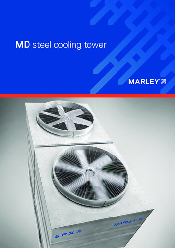
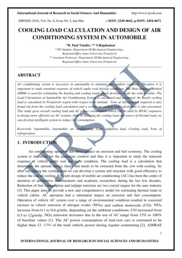
SUSTAINABLE MANUFACTURING FEATURES0 5 / 1 6ELIMINATINGCATALYST COOL DOWNas Critical Path in a TurnaroundBy Barney Smith, Turnaround Manager, Aggrekoc IntroductionAs with most major process plants, refineriesand petrochemical plants periodically need toshut down the entire plant or major portions ofit for major maintenance activities. These timeperiods are referred to as ‘turnarounds’ and aretime periods of intense activity. Once the plantshuts down, a considerable amount of money isbeing spent without any revenue being generated.Catalyst Cool-Down: The CommonTurnaround BottleneckMany refinery and petrochemical processes,such as hydrotreaters, hydrocrackers, andreformers, contain catalytic materials in theirreaction beds. It could be just one bed in onevessel, multiple beds in one vessel as shown inthe adjacent hydrocracker reactor process flowdiagram, or multiple beds in multiple reactors.Operating temperatures in these processes canbe very high. Once a plant begins an initialmaintenance shutdown, all of this catalyst(often hundreds of thousands or millionsof pounds) must be cooled from these highoperating temperatures down to near ambienttemperatures. Given the amount of catalyst andreactor metal mass, this takes time and is veryoften the bottleneck, or is on the ‘critical path’,for the entire turnaround.“Once a plant begins an initial maintenance shutdown, all of this catalyst(often hundreds of thousands or millions of pounds) must be cooled fromthese high operating temperatures down to near ambient temperatures.”— Barney Smith, Turnaround Manager, Aggreko10coolingbestpractices.com
SUSTAINABLE MANUFACTURING FEATURESNormal Cool-Down Method TakesDays and Consumes Large Volumesof Liquid NitrogenThe normal cool down process generallyconsists of two distinct phases. During thefirst phase, feed is blocked in and the furnaceis shut down. The recycle gas compressorcirculates hydrogen-rich gas through the feed/effluent exchanger (if there is a bypass aroundthe exchanger then it should be routed throughthe bypass), through the furnace (though thefurnace is not operating), and into the reactionvessel where the gas picks up heat from the hotcatalyst bed. The hydrogen gas is then cooledin fin-fans and a cold water exchanger beforeentering the high pressure low temperatureseparator (for this PFD; other units may havehigh pressure, high temperature separatorsand the cooling is only done on the gasstream and/or there may be low pressurelow or high temperature separators wherethe gas is separated) before repeating the loop.This approach can be used until the catalysttemperature reaches a certain point – normallyabout 150 – 200 deg F. After that point, therate at which heat is dissipated reaches a pointof diminishing returns. However, it is still toowarm for safe vessel entry.0 5 / 1 6In addition, this extra nitrogen is ordinarilyrelieved via the flare system, which lowers thecalorific value of the flare gas. This can causeproblems since the calorific value of the flaregas is subject to regulatory limits designedto prevent snuffing out the flare. If too muchnitrogen is used, supplemental fuel gas, such asLPG, must be added and subsequently burnedin the flare just to keep its calorific value withinregulatory limits. Obviously, using LPG in thismanner is economically wasteful since it couldbe recovered and sold. Another problem withnitrogen is that it consumes flare capacitywhose primary purpose is to be available foremergencies and other process uses.While relieving via the flare is the normal route,there are some refiners that relieve the nitrogenvia the fuel gas system. Obviously, this createsa whole other set of problems since nitrogen doesn’t combust and just takes up space inthe fuel gas system. Worse yet, it lowers thecalorific value of fuel gas causing significantcombustion problems in refinery furnaces.There are even other refiners that relieve thenitrogen straight to the atmosphere causingenvironmental problems.Another potential strike against liquid nitrogenis there are certain situations where injectingliquid nitrogen can cause metallurgicalproblems due to how cold the nitrogen is whenentering the vessel.For all these reasons, refiners andpetrochemical operators are open to otherideas on how to safely speed up the secondportion of the catalyst cool-down processwithout the costs or problems inherent withusing purchased liquid nitrogen.Traditionally, the second phase requirespurchasing liquid nitrogen with a vaporizer/feed system and injecting it ‘once through’into the reactor system, with the nitrogennormally exiting to the flare system. Giventhe very large mass of the reactor metal andcatalyst to be cooled, this operation generallytakes several days.Not only is this expensive due to the costof purchasing liquid nitrogen, it becomes alogistic nightmare since it requires a constantparade of liquid nitrogen road tanker truckscoming in and out of the refinery. This isespecially problematic during a turnaroundwhen minimizing traffic density in the refineryis an important consideration.coolingbestpractices.com11
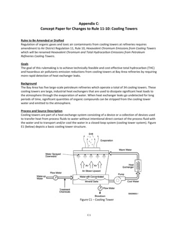
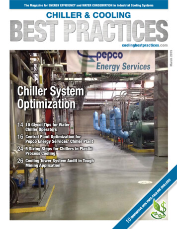
SUSTAINABLE MANUFACTURING FEATURES0 5 / 1 6ELIMINATING CATALYST COOL DOWN AS CRITICAL PATH IN A TURNAROUNDAn Improved Solution — Cools DownFaster, Without the Need for NitrogenIn order to overcome these problems duringthe Phase 2 cool down period, Aggreko hascreated an innovative, practical solutioncirculating coolant through an Aggrekoprovided, closed loop, chiller system whichcools down the gas leaving the recycle gascompressor discharge in an Aggreko-providedheat exchanger. This arrangement can cooldown the catalyst much faster than if the planthad used liquefied nitrogen. This eliminatesthe need for costly nitrogen.As the above diagram illustrates, the client’sequipment is denoted by the red or rosecolor whereas Aggreko-supplied equipmentis shown in blue.The following describes a typical processflow arrangement for the catalyst coolingsolution, though there are likely many differentalternatives depending on the actual clientprocess equipment configuration.Control valves for beds 1 and 2 are removed.The control valve for bed 3 remains intact,but the valves upstream and downstream ofthe control valve along with the bypass areall closed.For bed 2, the bypass and valve downstreamof the control valve are closed. However, thevalve upstream of the control is open and newpiping is installed and routed to the Aggrekoheat exchanger inlet.For bed 1, the bypass and valve upstream ofthe control valve are closed. However, the valvedownstream of the control is open and newpiping is installed and routed from the Aggrekoheat exchanger outlet to the inlet of the valvedownstream of the bed 1 control valve.On the client side, it is more advantageous toroute material leaving the reactor around thefeed/effluent exchanger. That’s because anyadditional heat picked up in this exchangerwill need to be relieved via the Aggrekoexchanger slowing the cooling process. Afterthe feed/effluent exchanger material will tendproceed through the furnace. Since the furnacewill not be providing any heat it just acts as awide spot in the line.The net effect of all these changes is to routegas from the recycle gas compressor dischargeto the heat exchanger so that the coldest gasenters at the top of the reactor. It’s importantto understand that the heat exchanger is placeddownstream of the recycle gas compressor sothat it cools the reactor gas further, but also toremove the heat of compression added duringthe compression cycle.The black piping lines in the diagram are thehard piping that already exists for the client’sequipment. On the other hand, connectionsshown in red are stainless steel braidedconnections for the cooling water circuit.Blue lines are hard piping lines that are addedfor this project. There is one hard piping lineadded that the client will make between theheat exchanger and the surge vessel. Thisexists to protect any hydrogen vapors thatcould enter the cooling water circuit if theexchanger were ever to leak since the processside pressure is higher than the cooling waterpressure. Vapors would then exit from the topof the surge vessel.System operation is straightforward. Chilledwater flows within a closed loop system leavingthe refrigerated chiller outlet at approximately40 F and entering the cold side of the heatexchanger. Gas from the discharge of therecycle gas compressor flows to the warm(shell) side of the exchanger. Cooling water iswarmed to about 55 F and sent to the processsurge vessel.The surge vessel is provided to enable gasseparation and venting in case of unexpectedgas leaks into the cooling water from therecycle gas side of the heat exchanger. Waterfrom the bottom of the surge enters thecirculating pump (spare is provided) suction,which pumps it back to the refrigerated chiller,thus closing the loop.The design temperature of the recycle gas inlettemperature to the heat exchanger is 200 Fwith the desired final reactor temperature of90 F or below. Since the design temperatureof the coolant inlet temperature is 40 F,the lowest temperature achievable is 70 F.However, it would approach temperaturesbelow 90 F asymptotically.“The net effect of all these changes is to route gas fromthe recycle gas compressor discharge to the heat exchangerso that the coldest gas enters at the top of the reactor.”— Barney Smith, Turnaround Manager, Aggreko12coolingbestpractices.com
SUSTAINABLE MANUFACTURING FEATURESModel Estimates Cool-Down TimeThe typical time to cool the reactor catalystdown from 200 F to less than 100 F using theAggreko solution without sending any gas to theflare is between 12-14 hours. However, Aggrekohas built a catalyst cooling correlation modelbased on the amount of catalyst mass, reactormass, number of catalyst beds, and otherfactors that will allow a client to better estimatethis time saving. a client more accuratelydetermine the ROI of this approach for theirparticular plant/unit.0 5 / 1 6path’ and allow the plant the ability to get theunits restarted in a shorter time period. Thequantifiable benefits of being able to reducethe time to cool down catalyst and gain vesselentry more quickly during a turnaround canvary significantly depending on:pp If the vessel is on the‘critical path’;pp How many days aresaved by moving it off the‘critical path’;pp How many units in the plantBenefits of Quicker Cool-DownThe good news is that the Aggreko phase 2cool down solution will allow entry to thereactor vessel much quicker. This may permitthe plant to move this
A plant manager estimated a potential financial loss of over 1,000,000 each day the plant was down. The incident occurred over the weekend and there was great concern that locating a replacement chiller with sufficient capacity would be challenging. Third-party temperature control provider Aggreko deployed a replacement chiller