Transcription
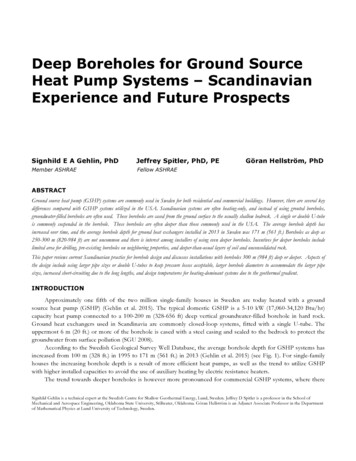
Deep Boreholes for Ground SourceHeat Pump Systems – ScandinavianExperience and Future ProspectsSignhild E A Gehlin, PhDJeffrey Spitler, PhD, PEMember ASHRAEFellow ASHRAEGöran Hellström, PhDABSTRACTGround source heat pump (GSHP) systems are commonly used in Sweden for both residential and commercial buildings. However, there are several keydifferences compared with GSHP systems utilized in the USA. Scandinavian systems are often heating-only, and instead of using grouted boreholes,groundwater-filled boreholes are often used. These boreholes are cased from the ground surface to the usually shallow bedrock. A single or double U-tubeis commonly suspended in the borehole. These boreholes are often deeper than those commonly used in the USA. The average borehole depth hasincreased over time, and the average borehole depth for ground heat exchangers installed in 2013 in Sweden was 171 m (561 ft.) Boreholes as deep as250-300 m (820-984 ft) are not uncommon and there is interest among installers of using even deeper boreholes. Incentives for deeper boreholes includelimited area for drilling, pre-existing boreholes on neighboring properties, and deeper-than-usual layers of soil and unconsolidated rock.This paper reviews current Scandinavian practice for borehole design and discusses installations with boreholes 300 m (984 ft) deep or deeper. Aspects ofthe design include using larger pipe sizes or double U-tubes to keep pressure losses acceptable, larger borehole diameters to accommodate the larger pipesizes, increased short-circuiting due to the long lengths, and design temperatures for heating-dominant systems due to the geothermal gradient.INTRODUCTIONApproximately one fifth of the two million single-family houses in Sweden are today heated with a groundsource heat pump (GSHP) (Gehlin et al. 2015). The typical domestic GSHP is a 5-10 kW (17,060-34,120 Btu/hr)capacity heat pump connected to a 100-200 m (328-656 ft) deep vertical groundwater-filled borehole in hard rock.Ground heat exchangers used in Scandinavia are commonly closed-loop systems, fitted with a single U-tube. Theuppermost 6 m (20 ft.) or more of the borehole is cased with a steel casing and sealed to the bedrock to protect thegroundwater from surface pollution (SGU 2008).According to the Swedish Geological Survey Well Database, the average borehole depth for GSHP systems hasincreased from 100 m (328 ft.) in 1995 to 171 m (561 ft.) in 2013 (Gehlin et al. 2015) (see Fig. 1). For single-familyhouses the increasing borehole depth is a result of more efficient heat pumps, as well as the trend to utilize GSHPwith higher installed capacities to avoid the use of auxiliary heating by electric resistance heaters.The trend towards deeper boreholes is however more pronounced for commercial GSHP systems, where thereSignhild Gehlin is a technical expert at the Swedish Centre for Shallow Geothermal Energy, Lund, Sweden. Jeffrey D Spitler is a professor in the School ofMechanical and Aerospace Engineering, Oklahoma State University, Stillwater, Oklahoma. Göran Hellström is an Adjunct Associate Professor in the Departmentof Mathematical Physics at Lund University of Technology, Sweden.
is space, time and money to save by drilling fewer but deeper boreholes. Large GSHP systems in Scandinavia are nowcommonly drilled to a depth of 200-300 m (656-984 ft.). The three largest GSHP systems in Scandinavia today areAkershus Hospital, Norway, with 228 boreholes to a depth of 200 m (656 ft.), Karlstad University Campus, Sweden,with 204 boreholes of 240-250 m (787-820 ft.) depth, and SOK Logistic Centre in Sibbo, Finland, with 150 boreholesto 300 m (984 ft.).Incentives for deeper boreholes include limited area for drilling, pre-existing boreholes on neighboringproperties, and deeper-than-usual layers of soil and unconsolidated rock. For pure heat extraction systems there is alsoan interest in taking advantage in the increased temperature with depth, due to the geothermal gradient, however, as isshown in this paper, this issue is not as simple as some tend to believe.Figure 1Average borehole depth and deepest borehole, from SGU Well Database (Gierup 2015).This paper reviews current Scandinavian practice for borehole design and discusses technical, thermal andeconomic considerations with boreholes drilled to 300 m (820 ft.) depth or more. Aspects discussed include usinglarger pipe sizes or double U-tubes to keep pressure losses acceptable, larger borehole diameters to accommodate thelarger pipe sizes, increased short-circuiting due to the long lengths, and design temperatures for heating-dominantsystems due to the geothermal gradient.SCANDINAVIAN DESIGN OF GSHP BOREHOLESThe typical Scandinavian GSHP design and design conditions differ from GSHP systems in many othercountries. This has to do with climatic and geological conditions, as well as issues related to building codes and otherregulations, energy source availability and pricing.Geological and Climatic ConditionsThe Swedish geology is predominantly crystalline rock with shallow overburden, generally high quartz content,and high thermal conductivity. Groundwater level is generally high (a few meters below the ground surface). There areareas with rich overburden and sedimentary deposits, mainly in the south and middle parts of Sweden and on theislands Öland and Gotland. Similar conditions with predominantly crystalline rock and high groundwater levels arefound in Norway and Finland. The Swedish Geological Survey (SGU) has provided guidelines for construction ofwells for GSHP systems since 1997(SGU 2008), and collects data on all groundwater wells and GSHP boreholes inSweden through the Well Database.The Swedish well construction guideline requires steel casing of the uppermost part to a minimum depth of 6 m(20 ft.) and with at least 2 m (7 ft.) drilled into hard bedrock and sealed with concrete. The guidelines allow forungrouted, groundwater-filled boreholes, which is how the vast majority of Scandinavian borehole heat exchangers
are constructed.The Scandinavian climate is heating dominated, but for commercial GSHP systems both heating and cooling areused. Average ground temperature varies between 11 C (51.8 F) in the south and 2 C (35.6 F) in the north.Design ConditionsScandinavian GSHP systems are generally designed for a minimum design EFT of 0 C (32 F), though in thenorthern part of Sweden the minimum temperature may be allowed to fall below 0 C (32 F). Boreholes are allowed tofreeze at maximum heating load conditions.Closed-loop single U-tubes are the most commonly used collectors, though for commercial GSHP systemsdouble U-tubes are often used. Tube size is typically 40x2.4 mm (1½”) PN10 SDR17 PE100 for single U-tubes and32x2.0 mm (1¼”) PN10 SDR17 PE100 for double U-tubes. Coaxial ground heat exchangers have been usedoccasionally. A 20-28% ethanol/water solution is predominantly used as heat carrier fluid in the collector pipes.DEEP BOREHOLESBoreholes for deep geothermal use (direct use and power production) have limited potential in Scandinavia. Themarket is completely dominated by shallow geothermal energy systems such as typical GSHP systems with verticalboreholes in rock. These boreholes are rarely drilled deeper than 300 m (984 ft.) in Scandinavia, and less than that incentral Europe and North America. Hence experience from ground heat exchangers in boreholes deeper than 300 m(984 ft.) is scarce. Rybach and Hopkirk (1995) discuss two converted “dry” geothermal boreholes in Switzerland. The1700 m (5577 ft.) borehole at Reinach, near Basel, and the 2300 m (7546 ft.) deep borehole at Weggis are both usedfor heating of buildings. They conclude that the economics depend not only on the size and proximity of the energyuser, but also on the temperature at which heat is to be delivered. They also conclude that failed geothermal orhydrocarbon exploration boreholes are feasible to use for GSHPs provided that the full drilling cost is not included.Kohl et al. (2002) also cover the Weggis borehole and Kohl et al (2000) describe the performance over twoconsecutive years of operation of a 1200 m (3937 ft.) deep borehole that was drilled in the early 1990’s in Weissbad,Switzerland. The borehole was initially meant to reach a waterfilled fracture for deep geothermal heat extraction, butthe formations proved to be dry, and the project was abandoned. Instead a borehole heat exchanger was installed touse the borehole with a GSHP. The temperature at the bottom of the borehole was measured at 45 C (113 F).Huchtemann and Müller (2014) and Dijkshoorn et al. (2013) treat a 2500 m (8202 ft.) deep borehole with a coaxialborehole heat exchanger for space heating and cooling of a university building in the city Aachen, Germany.More recent examples of deep boreholes drilled purposely as borehole heat exchangers are reported fromSwitzerland and Norway. In mid-March 2015, a European geothermal drilling company reported (De Varreux 2015)that they had installed their first 750 m (2460 ft) deep borehole heat exchanger (“geothermal probe”) in Lausanne,Switzerland. The borehole is the first in a series of 150 deep borehole heat exchangers to be installed during theperiod 2015-2018 to provide district heating to a new housing and commercial complex area. The heat exchanger wasa HPR (high pressure) PN80 double U-tube with outer diameter 50 mm (2’’). In 2014 the same company installedeight borehole heat exchangers to a depth of 500 m (1640 ft.), heating 64 apartments in four buildings (De Varreux2015). Schwenke (2013) describes the Skoger School project in Drammen, Norway, which is heated by five boreholesof 500 m (1640 ft) depth. The boreholes are fitted with single U-tube collectors with OD 50 mm (2”) and ID of 44mm (1.7”). The borehole has a diameter of 140 mm (5.5”).Holmberg et al. (2015) show results from numerical model simulations of borehole heat exchangers of 600 m(1969 ft), 800 m (2625 ft) and 1000 m (3281 ft) depth. The borehole is fitted with a coaxial heat exchanger consistingof a central polypropylene pipe and an outer thin polyethylene liner, as described in more detail by Acuña (2013). Thesimulations are done to describe performance over time, and to determine average specific thermal load and energyextracted. A geothermal gradient of 0.02 K/m (0.006 K/ft.) was used. The authors conclude that deep borehole heatexchangers can sustain a higher average specific heat load than conventional borehole heat exchangers due to the
higher temperature level in the borehole, and that deep boreholes may be suitable for GSHP installations in areas withlimited space and negatively balanced load profiles.Pipe and Pressure ConsiderationsThe difference in density between the borehole filling and the heat transfer fluid in the piping may be an issue indeep boreholes. If the heat transfer fluid has a lower density the resulting external pressure on the pipe may causebuckling. Common SDR-17 polyethylene pipes can withstand an external pressure of 1.4 bar (20.3 psi) whereas SDR11 pipes can handle 5.7 bar (82.7 psi) before buckling (Kalantar 2015). Figure 2 shows the differential pressure versusdepth for three combinations of heat carrier fluid and borehole filling. The worst-case for a groundwater-filledborehole occurs when a less dense antifreeze mixture is used – as shown in Figure 2, it’s possible that there is a risk ofbuckling when SDR-17 is used and borehole depth exceeds 300 m (984 ft).However, although the vast majority of boreholes in Scandiavia are groundwater filled, there are situations wheregrouting is required. During the grouting process the grouting mixtures are heavier than the heat transfer fluids andwill cause an external pressure on the pipe. Available grouting mixtures vary in density from 1100 to 2000 kg/m3 (69125 lb/ft3) during injection, where the heavier materials usually have higher thermal conductivities. As shown inFigure 2, differential pressures significantly exceed buckling limits for thermally-enhanced grout, regardless of the heatcarrier fluid. It is common practice to use pressurized SDR-11 pipes for grouted boreholes, but even then, it may beimpossible to safely grout the borehole in one step without allowing part of the grout to set up. A multi-step groutingprocess adds complexity and costs.Figure 2Differential pressure in borehole with un-pressurized pipes.Pipes are installed in the borehole when the ground temperature is at undisturbed conditions. In groundwaterfilled boreholes the pipe will expand or contract due to heating/cooling during operation. If the pipe is heated totemperatures above those experienced during installation, the expansion may cause the U-bend to repeatedly pushagainst the bottom of the borehole. This has occasionally led to failure of the pipe. The linear coefficient of thermalexpansion for PE100 is 1.3·10-4 m/m·K (ft/ft·K), which means that a 300 m (984 ft) pipe will change 0.6 m (1.9 ft.)in length when changing temperature from 0 C (32 F) to 15 C (59 F), while a 500 m (1640 ft) pipe will changeapproximately 1 m (3.28 ft.). Therefore, care must be taken to suspend the U-tube higher in deeper boreholes.Considerations Related to DrillingThe governing drilling techniques for GSHP borehole drilling in Scandinavia today are air-driven or water-drivendown-the-hole-hammer (DTH) drilling. With common compressors suitable for urban use, of up to 35 bar (507.6psi), and lift capacity of 50-70 kN (5.62-7.87 tons) for air-driven DTH drilling, the theoretical maximum boreholedepth is 300 m (984 ft.), where the counter pressure from groundwater will be too high for the hammer to work. Forwater-driven DTH drilling, there is no counter-pressure from groundwater, but a limiting factor is flow losses to
fractures in the rock. Even larger DTH drill rigs with capacity of DTH drilling to 800 m (2625 ft.) depth exist inlimited numbers, but are infeasibly large for urban drilling.GSHP boreholes are usually produced at low-cost with small demands on drilling precision. The deviation fromtargets depends partly on drilling speed and to some extent on the geological structure. The deviation increases withdepth, and is not linear. This means the risk for intersecting another borehole increase with borehole depth. Higherdemands on precision involve smaller tolerances, increased material cost and fuel consumption, and decreased overallrate of penetration, leading to higher costs for deep boreholes.Thermal ConsiderationsThe heat energy budget for the subsurface is largely a balance between the surface boundary conditions andgeothermal heat flux from the centre of the earth. Insolation varies with time and location, but for Scandinavia theaverage annual net insolation is on the order of a 100 W/m2 (31.7 BTU/hr/ft2), while the geothermal heat flux is inthe range of 0.04-0.09 W/m2 (0.013-0.029 BTU/hr/ft2) (Banks 2012). Hence the contribution to GSHP systems fromgeothermal heat is small compared to that of insolation. The geothermal heat flux causes a thermal gradient that issuperimposed on the annual average ground surface temperature, increasing the ground temperature with depth. InScandivanian bedrock the geothermal gradient is on the order of 1-3 K per 100 m (0. 3-0.8 K per 100 ft). That meansthat if the annual average ground surface temperature is 10 C (50 F) and the geothermal gradient is 1.5 K/100 m(0.0046 K/ft.), then the temperature at 300 m (984 ft.) depth will be 14.5 C (58 F) and at 500 m (1640 ft.) depth itwill be 17.5 C (63.5 F).Depth emperature12531151Temperature ( F)55)(CratupTemTemperature ( pth(m)Figure 3Measured ground temperature in a 270 m (886 ft.) deep borehole at Norra Frescati, Stockholm.In urban areas (where deep boreholes are of the most interest) heat leakage from buildings can significantlyimpact the temperature profile along the borehole. The building footprint provides a stable heat flux from thebuilding to the ground. The thermal front may reach more than 100 m (328 ft.) below the surface depending on howmany years buildings have existed on the site. In Figure 3 the ground temperature was logged at 5 m (16 ft.) intervalsdown a 270 m (886 ft.) borehole in Stockholm, where the average ground surface temperature for an undisturbedgreen field site would be 8 C (46 F). The measured temperature gradient is stable between 150 m (492 ft) and 270 m(886 ft). Above that, the temperature measurements show considerable influence of a nearby building, leading to 100m (328 ft) deep “heat wave”. Ground temperature and average ground temperature to depth are extrapolated below270 m. The “heat wave” means that the presumed advantage of deeper boreholes (higher average groundtemperature) can be difficult to realize on urban sites with disturbed ground temperatures. For example, on this site, aborehole 350 m deep would have approximately the same average temperature as a 100 m deep borehole.
All vertical ground heat exchangers are affected by short-circuiting – that is, heat transfer between the upwardflowing and downward-flowing legs of the heat exchanger. Though this is often negligible for typical boreholes, theshort-circuiting effect increases as either the depth or conductance between the legs increases and/or as the mass flowrate in the heat exchanger decreases. (I.e. there is a direct relationship between the short-circuiting heat transfer andthe number of transfer units (NTU) as there would be for any heat exchanger. With regards to short-circuiting heattransfer we prefer a very low effectiveness, though). As with conventional heat exchangers where the LMTD or εNTU approaches may be used, multiple approaches to analyze this problem may be utilized. Marcotte and Pasquier(2008) and Beier et al. (2012) suggested approaches for estimating the mean temperature difference. Hellström (1991)derived expressions (cf. pp. 94-99) that give an effective borehole thermal resistance that includes the thermal shortcircuiting effect. See also Claesson and Hellström (2011). These expressions are derived for two idealized boundaryconditions – the borehole wall being at a uniform temperature and the borehole having a uniform heat transfer rate –neither of which applies perfectly. A mean value between the two expressions can be taken as a best approximation.Both expressions are formulated to give the ratio of the effective borehole thermal resistance to the local or twodimensional borehole thermal resistance (Rb). These two expressions are calculated for an otherwise-typicalgroundwater-filled borehole where the flow rate has been fixed at 3.1 m3/h (13.65 GPM) and the results are shown inFigure 4. As can be seen there, at 100 m (328 ft), the ratio is less than 1.02, so the short-circuiting has less than a 2%effect on the effective borehole thermal resistance. However, for deep boreholes the short-circuiting effect canincrease significantly if the flow rate is not increased proportionally.Apart from the short-circuiting effect inside the borehole, which increases with depth, the temperaturedifference between the top and the bottom of the borehole will to some extent counteract the initial benefit of thegeothermal gradient. During heat extraction, the heat transfer fluid will increase in temperature as it travels from topto bottom, and will be warmest at the U-bend. On its way up, the fluid will at some point along the borehole reach alevel where the surroundings are colder than the fluid, and hence the fluid will start rejecting heat to the ground. Thispoint occurs where the local borehole temperature equals the current average borehole temperature, and will changeover time, moving upwards, as the borehole temperature evens out. This effect will be increasingly significant fordeeper 5Uniformq1.41.4Rb*/RbUniformT1.31.3Boreholediam. 110mm(4.33in.)U- ‐tubeI.D. 35.2mm(1.39in.)U- ‐tubeO.D. 40mm(1.57in.)Flowrate Boreholedepth(m)Figure 4Effect of thermal short-circuiting on effective borehole thermal resistance.Head Loss ConsiderationsAnother aspect of deep borehole design is the possibility for excessive pressure loss leading to high circulatingpump energy consumption. In order to keep the pressure drop reasonable, large diameter U-tubes and/or double Utube heat exchangers may be needed, and, consequently, larger diameter boreholes may also be necessary. As anexample, consider a case with a nominal design heat extraction rate of 40 W/m (41.6 Btu/hr/ft) where the design
flow rate is chosen so that a 4 C (7.2 F) temperature difference across the ground heat exchanger is maintained.Pressure drops under design conditions have been calculated for single (1U) and double (2U) U-tubes made fromSDR-17 HDPE with outer diameters of 40 mm (1.57 in.) and 50 mm (1.97 in.). The pressure drop vs. boreholelength for the heat exchangers are compared in Figure 5 to Mescher’s (ASHRAE 2011) criterion that a properlydesigned borefield should be kept to less than 25 ft (7.6 m) of head loss with a total system pressure drop ofmaximum 50 ft (15.2 m). As the borehole gets deeper, it is harder and harder to meet the criteria and even the largerdiameter double U-tube fails to meet the criterion at 500 m (1640 ft).Figure 5Pressure drop for 40 mm (1.57 in.) and 50 mm (1.97 in.) single and double U-tubes.Economic ConsiderationsThe cost per drilled meter is not a linear function. There is first of all a setup cost for each borehole. Theuppermost steel cased 6 m (20 ft.) or more through the overburden and at least 2 m (7 ft.) into bedrock is 3-5 timesmore expensive per unit than the un-cased borehole below. In theory the real drilling cost increases exponentially withdepth due to increasing energy use and wearing of the drill bit. At a certain depth, depending largely on the hardnessof the rock, the drill bit must be recovered and changed due to wearing. This procedure is time consuming andincreasingly complicated as the borehole depth increases. The risk for complications along the borehole due toborehole deviation, clogging of the borehole, etc., increases with increasing depth. For practical reasons most drillerscharge the same price per unit of length down to at least 200 m (656 ft.). For deeper intervals an estimate of additionalcost would be in the order of 10% for the following 50 m (164 ft.), and around 20% if the borehole be drilled deeper(Geotec 2015). Drill rigs used for oil drilling use a different technique - decidedly more expensive than DTH drilling.CONCLUSIONSAs Scandinavian GSHP boreholes tend to be drilled to increasing depth, there are a number of factors toconsider in evaluating the benefits of deeper boreholes. Typical reasons for drilling to greater depth include reachinghigher temperatures due to the geothermal gradient, decreasing the number of boreholes so that less upper steelcasing is needed, and being able to use smaller land areas for the well field in urban areas. These advantages can beoffset by several factors. The thermal efficiency of the deeper heat exchanger is negatively influenced by increasingthermal short-circuiting between the upward and downward channels, as well as the temperature gradient itself,causing increased heat losses from the heat transfer fluid on its way to the surface. For urban sites, the groundtemperature profile may deviate significantly from the undisturbed case, such that average ground temperature doesnot increase with depth as quickly as anticipated. Installation costs per unit length of borehole may be significantlyhigher due to increased drilling and grouting costs. Another complicating factor is the increased pressure drop, whichwill, even for larger pipe sizes and double U-tubes, make it difficult to keep pump energy consumption suitably low, asthe depth approaches 500 m (1640 ft.). Complications with thermal efficiency, actual temperature profiles and
pumping energy must be carefully considered in any deep borehole design. Likewise, for situations where availablesurface area is scarce, deep boreholes may or may not be a good solution, but the economics with increased drillingand installation costs must also be considered.ACKNOWLEDGMENTSAll three authors were supported by their employers. In addition, the second author was supported by theFulbright Commission as the Fulbright Distinguished Chair of Alternative Energy Technology at Chalmers Universityof Technology in Gothenburg, Sweden for the 2014-2015 academic year. Financial support from all of these sourcesis gratefully acknowledged.REFERENCESAcuña J. 2013. Distributed thermal response tests – new insights on u-tube and coaxial heat exchangers in groundwaterfilled boreholes. PhD thesis, KTH, Stockholm.ASHRAE. 2011. Ground Source Heat Pump Systems: Putting the Earth to Work for You. Ashrae Webcast Dvd.Banks, D. 2012. An Introduction to Thermogeology. Ground Source Heating and Cooling. 2nd Ed. Oxford: Wiley-Blackwell.Beier, R. A., J. Acuña, P. Mogensen and B. Palm. 2012. Vertical temperature profiles and borehole resistance in a U-tubeborehole heat exchanger. Geothermics 44: 23-32.Claesson, J. and G. Hellström. 2011. Multipole method to calculate borehole thermal resistances in a borehole heatexchanger. HVAC&R Research 17(6): 895-911.De Varreux, N. Augsburger Forbes. March 2015, LinkedIn group GeoExchange. First operational 750 m (2460 ft)geothermal probe installed in Lausanne (Switzerland).Dijkshoorn, L., S. Speer and R. Pechnig. 2013. Measurements and Design Calculations for a Deep Coaxial Borehole HeatExchanger in Aachen, Germany. International Journal of Geophysics. Volume 2013, Article ID 916541, 14 pages.Available at http://dx.doi.org/10.1155/2013/916541Gehlin, S., Andersson, O., Bjelm, L., P.G. Alm, and J.E. Rosberg. 2015. Country Update for Sweden. Proceedings WorldGeothermal Congress 2015, Melbourne, Australia, April 19-24, 2015.Geotec. 2015. Personal communication with Geotec - Svenska Borrentreprenörers Branschorganisation. (The SwedishDrilling Contractors Organization), July 2015.Gierup, J. 2015. Personal communication. The Swedish Well Database, Swedish Gelogical Survey.Hellström, G. 1991. Ground Heat Storage – Thermal Analyses of Duct Storage Systems - Theory PhD Doctoral Thesis,University of Lund.Holmberg, H., Acuña, J., Næss, E., and O.K. Sønju. 2015. Deep Borehole Heat Exchangers, Application to Ground SourceHeat Pump Systems. Proceedings World Geothermal Congress 2015. Melbourne, Australia, April 19-25, 2015.Huchtemann, K., and D. Müller. 2014. Combined simulation of a deep ground source heat exchanger and an officebuilding. Building and Environment 73:97-105.Kalantar, A. 2015. Personal communication, July 10th. Muovitech.Kohl, T., M. Salton and L. Rybach. 2000. Data Analysis of the Deep Borehole Heat Exchanger Plant Weissbad(Switzerland). Proceedings World Geothermal Congress 2000, Kyushu - Tohoku, Japan, May 28 - June 10, 2000. Pp.3459-3464.Kohl, T., R. Brenni and W. Eugster. 2002. System performance of a deep borehole heat exchanger. Geothermics 31:687–708.Marcotte, D. and P. Pasquier. 2008. On the estimation of thermal resistance in borehole thermal conductivity test.Renewable Energy 33: 2407-2415.Rybach, L., and R.J. Hopkirk. 1995. Shallow and Deep Borehole Heat Exchangers. Achievements and Prospects.Proceedings, World Geothermal Congress 1995, Firenze, Italy, May 18 - 31, 1995, pp. 2133-2138.Schwenke, A. 2013. Analysis and modeling of deep energy wells. Master’s Thesis. Dept. of Energy and Process Engineering,NTNU, Norway. Available online at: FULLTEXT01.pdfSGU. 2008. Normbrunn-07. Att borra brunn för energy och vatten – en vägledning. (In Swedish. Guideline for design ofwells for energy and water). The Swedish Geological Survey, Uppsala, Sweden.
The Swedish well construction guideline requires steel casing of the uppermost part to a minimum depth of 6 m . hydrocarbon exploration boreholes are feasible to use for GSHPs provided that the full drilling cost is not included. Kohl et al. (2002) also cover the Weggis borehole and Kohl et al (2000) describe the performance over two .