Transcription
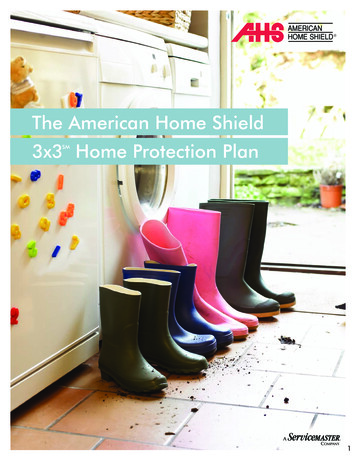
BUILDING CONTRACTOR/HOME OWNERTO REVIEW AND VERIFY ALL DIMENSIONS,SPECS, AND CONNECTIONS BEFORECONSTRUCTION BEGINS.BUILD AS PER UBC, IRC OR CURRENTLOCAL CODE REQUIREMENTSPage 1Page 2Page 3Page 4Page 5Page 6Page 7Page 8Cover PageMain Floor PlanFoundation PlanElevation PlanTypical Section DetailsFloor and Roof Framing PlanCabinet & Main ElectricalMisc DetailsTo the best of my knowledge these plans aredrawn to comply with owner's and/ or builder'sspecifications and any changes made on themafter prints are made will be done at the owner'sand / or builder's expence and responsibility. Thecontractor shall verify all dimensions and encloseddrawing. SDSCAD is not liable for errors onceconstruction has begun. While every affort hasbeen made in the preparation of this plan to avoidmistakes, the maker can not guarantee againsthuman error. The contractor of the job must checkall dimensions and other details prior toconstruction and be solely responsible thereafter.All calculations and member sizing should beverified for your building by a certified buildingofficial.CLIENTDATEDRWN BYCHK'D BYDATEREVISIONSJOB NO.SHEET NO.Sample House Plan www.sdscad.com1Note: Paper size 11 x 17 B - size, scale is as stated if printed on 22 x 34 - D size scale is 2X@COPYRIGHT SDSCAD Specialized Design SystemsOF8P O Box 374 Mendon, Utah www.sdscad.com email: sdscad@pcu.netResidential DesignSDS-CADSpecialized Design SystemsSample House Plan www.sdscad.com Plans for as low as 9.99Custom Home DesignPlan #211By SDS-CAD Specialized Design Systems
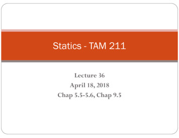
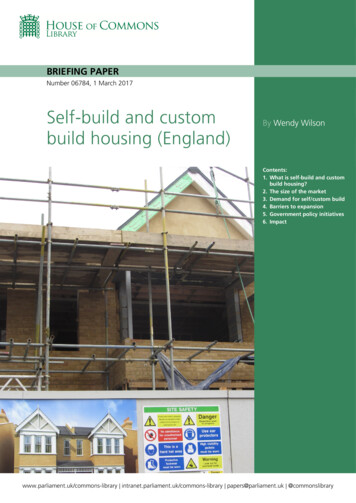
Residential Design24'-0"2'-2"6'-2"Vent Through RoofVent to ExteriorVent to zed Design Systems12'-8"3'-0"MASTER BDRM1'-9"5'-5"BATH24'-8"8'-0" x 6" x 11'-6"4068R-38 MinR-19 MinR-13 Min3'-0"CeilingsWall above gradeWall interior below grade12'-0"INSULATION 2"LIVING11'-5" x 16'-10"40683'-2"26683'-0"2'-4" 1'-9"BEDROOM1'-0"11'-6" x 4-PANEL4-PANELEXT. CROSS@BUCKBIFOLDEXT. SLIDER-GLASSBIFOLD1'-0"WH2'-4" 1'-9"3'-0"3'-0"406830403'-2"8'-0" x 5'-0"HEIGHT80 "80 "80 "80 "80 "80 "3'-7 1/2"30403'-0"3'-8"DESCRIPTIONDOUBLE HUNGDOUBLE HUNGMULLED UNIT5'-5"DOOR SCHEDULEDIMENSIONSWIDTH17 3/4X80X1 3/8" 18 "30X80X1 3/8"30 "36X80X1 3/4"36 "24X80"24 "72X80"72 "37X80"37 "HEIGHT36 "48 "48 "13'-4"SIZE166826683068406860686268WINDOW SCHEDULEDIMENSIONSWIDTH36"X36"36 "36"X48"36 "74"X48"74 251511FLOOR11110'-5" x '-2"NUMBERW01W02W0310'-4"62683'-8"10'-6"9'-0"3'-7 1/2"2'-2"406811'-5" x TE2'-10"3'-0"2'-0"DRWN BYCHK'D BY11'-10"DATE24'-0"REVISIONSJOB NO.MAIN FLOOR PLANSCALE 1/8" 1'SHEET NO.Sample House Plan www.sdscad.com2Note: Paper size 11 x 17 B - size, scale is as stated if printed on 22 x 34 - D size scale is 2X@COPYRIGHT SDSCAD Specialized Design SystemsOF8P O Box 374 Mendon, Utah www.sdscad.com email: sdscad@pcu.net3'-0"62402'-0"4068Range HoodsAll Bath FansDryer Vent12'-0"3'-0"48'-0"Sample House Plan www.sdscad.com Plans for as low as 9.99VENTING SCHEDULE
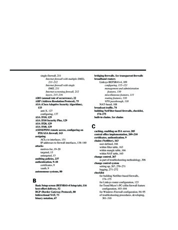
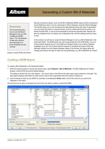
Residential DesignConcrete:1. All slabs are to be 4" concrete over 4" gravel unless otherwise noted on the plans.2. Concrete to be ACI 301-66, Type II cement, 2500 psi at 28 days, 5" maximum slump.3. Reinforcing to be ASTM A615-Bars with Fy 60 ksi lamp 30 diameterminimum at splices or weld per ACI Std.4. Concrete design based on Fc 2000 psf, Fc 2500 psi for quality only.5. Anchor bolts shall be A-307 embedded 7" minimum into concrete or masonry grout.Simpson HPAHD strap location markerSee detail for cantileverFOOTING SCHEDULE20" x 10" Min18" x 10" Min20" x 10" Min18" x 10" Min48'-0"41'-8"HOUSE WALLSDECKS & PORCHESBEARING WALLGARAGE WALL24 x 24 x 10 footing6 x 6 PT post equally spaced5 1/2" x 11 7/8" LVL BeamMin 2 #4 Rebar Horizontalon undisturbed or compacted soil6'-4"BRACED WALL PANEL4X8 SHT. ON FOUNDATION.NAIL W/8d NAILS @6" O.C.EDGES @12" O.C. IN FIELD.NAIL BOTTOM TO SILL PLATE.CLIENTDATE12'-0"12'-0"DRWN BY24'-0"CHK'D BYDATEREVISIONSALTERNATE BRACE WALL PANELSPROVIDE (2) STRAPS FOR B.W.P.FOUNDATION PLANSCALE 1/8" 1'JOB NO.SHEET NO.Sample House Plan www.sdscad.comNote: Paper size 11 x 17 B - size, scale is as stated if printed on 22 x 34 - D size scale is 2X@COPYRIGHT SDSCAD Specialized Design Systems3OF8P O Box 374 Mendon, Utah www.sdscad.com email: sdscad@pcu.netSDS-CADSpecialized Design SystemsBRACED WALLS BWP AND ALT BRACED WALL ABWP OPTIONSBrace all exterior walls and cross-stud partitions at each end of building and atleast every 25' of length by one of the following:a. Simpson WB 126 wall bracing with 3-16d nails at eachend and 1-8d nails at each stud.b. Plywood sheathing of a minimum thickness of 3/8 inch.c. Continuous bracing from floor to floor48'-0"Sample House Plan www.sdscad.com Plans for as low as 9.9924'-0"
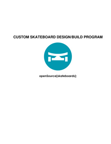
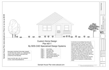
SCALE 1/8" 1'SCALE 1/8" 1'Exterior Finish to be determined byhomeowner and to meet ES6/12PITCHSidingCLIENTDATEDRWN BYCHK'D BYDATEREVISIONSREAR ELEVATIONFRONT ELEVATIONSCALE 1/4" 1'JOB NO.SHEET NO.Sample House Plan www.sdscad.com4SCALE 1/4" 1'Note: Paper size 11 x 17 B - size, scale is as stated if printed on 22 x 34 - D size scale is 2X@COPYRIGHT SDSCAD Specialized Design SystemsOF8P O Box 374 Mendon, Utah www.sdscad.com email: sdscad@pcu.netResidential DesignSDS-CADSpecialized Design SystemsSample House Plan www.sdscad.com Plans for as low as 9.99LEFT ELEVATIONRIGHT ELEVATION
7.8.9.MAIN FLOOR FRAMINGSCALE 1/16" 1'9 1/2" I-Joists 16"o.c Floor Joists.ROOF FRAMINGSCALE 1/16" 1'SEE GENERAL SPECS ANDNOTES FOR FRAMING DETAILS8/12 PitchCLIENTDATEDRWN BYCHK'D BYPRE-ENGINEERED ENERGY TRUSSES AS SUPPLIED BY TRUSS MANUFACTURER1. Trusses to be 24" O.C.2. Attic access min 22 1/2" x 30" were most convenient. For all areas greater than 30"3.Place vaults where possible as indicated on the floor plan4. Install all trusses as per truss manufacturer installation guidelines.5. 8/12 and 6/12 PitchDATEREVISIONSJOB NO.SHEET NO.Sample House Plan www.sdscad.com5Note: Paper size 11 x 17 B - size, scale is as stated if printed on 22 x 34 - D size scale is 2X@COPYRIGHT SDSCAD Specialized Design SystemsOF8P O Box 374 Mendon, Utah www.sdscad.com email: sdscad@pcu.netSample House Plan www.sdscad.com Plans for as low as 9.995.6.Fascia to be 2"x Douglas Fir.For soffit size see details.For spans and dimensions refer to floor plans.Trusses are to be an approved truss design from the truss manufacture's engineer.Install as per engineers specsUse Simpson H-1 hurricane anchors at each truss or rafter to wall connection.Solid blocking required between joists, rafters, and trusses over all bearing walls.Such blocking shall be 1 ½" minimum thickness and full depth of joists, rafters, or trusses.Minimum header sizes shall be according to the header size table unless otherwise noted.Basis of design roof live/snow load of 37 psf, and roof dead load of 15 psf.Plywood roof decking to be Min ½" thick, 24/0, CDX or 5/8 wafer.SDS-CADSpecialized Design Systems1.2.3.4.Residential DesignRoof Framing:
1.2.3.4.5.6.7.8.9.10.11.12.Minimum header sizes shall be according to the following table unless otherwise noted.Header sizes (single story construction)2'-0" to 4'-0" Span 2-2x4's4' to 6'-0" Span 2-2x6's6' to 8'-0" Span 2-2x8's8' to 10'-0" Span 2-2x10's10' to 12'-0" Span 2-2x12'sHeader sizes (two story construction)2'-0" to 3'-0" Span 2-2x4's3' to 5'-0" Span 2-2x6's5' to 7'-0" Span 2-2x8's7' to 8'-0" Span 2-2x10'sBrace all exterior walls and cross-stud partitions at each end of building and at least every25' of length by one of the following:a.Simpson WB 126 wall bracing with 3-16d nails at each end and 1-8d nails at each stud.b.Plywood sheathing of a minimum thickness of 3/8 inch.Fire stopping:a.Fireblock stud spaces over 10' in height, furred spaces, soffits, drop ceilings, cove ceilings,stair stringers at top and bottom of run, bearing walls and ceiling joist lines, etc.Firestopping shall consist of 2" nominal lumber.b.Firestop openings around vents, pipes, ducts, chimneys, and fireplaces at ceilingand floor levels with approved noncombustible materials.CDX plywood is not approved where exposed to weather, i.e., roof overhangs.Exterior wall framing to be 2"x4" studs at 16" o.c. Interior wall, framing at non-bearing wallsto be 2"x4" studs at 24" o.c. and at bearing walls 2"x4" studs at 16" o.c. with double top plate.Shear wall to be 3/8" CDX plywood applied horizontally.All stress grade lumber shall comply with WCLA specs and bear approval stamp on all pieces in place.Framing lumber shall be Douglas Fir construction grade Fb 1450 or better unless otherwise noted.Nailing to be per current U.B.C. unless otherwise noted.All bearing partitions shall have double top plates.Structural glued laminated timbers to be stamped by an approved agency.Use redwood or pressure treated sole plates at all exterior walls.FULL HOUSEFRAMING SECTIONSCALE 1/8" 1'CLIENTFloor Framing:DATE1.2.3.4.DRWN BY5.6.7.8.9.All floor joist to be Douglas Fir #2 or T.J.I. @ 16" o.c. unless otherwise noted.For spans and dimensions refer to floor plans.Use Simpson H 2.5 hurricane anchors at each floor joist to bearing wall connection.Solid blocking between joists over all bearing walls, and midspans such blocking shallbe 2" minimum thickness and full depth of joists.Minimum header sizes shall be according to the header size table unless otherwise noted.Basis of design: floor live load of 40 psf, and floor dead load of 15 psf.Floor decking to be ¾" thick T & G wafer board.Joist hangers to be Simpson U210 or equal unless otherwise noted.Double joists and or double blocking at all interior walls.CHK'D BYDATEREVISIONSJOB NO.SHEET NO.Sample House Plan www.sdscad.com6Note: Paper size 11 x 17 B - size, scale is as stated if printed on 22 x 34 - D size scale is 2X@COPYRIGHT SDSCAD Specialized Design SystemsOF8P O Box 374 Mendon, Utah www.sdscad.com email: sdscad@pcu.netResidential DesignSDS-CADSpecialized Design SystemsSample House Plan www.sdscad.com Plans for as low as 9.99General framing: (Douglas Fir)
15.16.17.18.ELECTRICAL SCHEDULEDESCRIPTION220VDUPLEXDUPLEX (WEATHERPROOF) - COLOR LIGHT GRAY (MATTE)EXHAUSTGFCIHALF CONE - LIGHTING GREYHALF DOME LIGHT - LIGHTING GREYPORCH LANTERNSINGLE POLETHREE WAYSMOKE DETECTORSYMBOLDESCRIPTION3METER SOCKETPANEL BOXCEILING FAN W/ LIGHTSDFLUORESCENT LIGHT FIXTURE33110V CEILING LIGHT FIXTURE110V RECESSED LIGHT CABINETDIMENSIONS12X12X30 "12X24X36 "18X24X36 "18X24X36 "24X12X30 "24X24X30 "24X24X36 "30X12X17 "30X24X36 "30X24X36 "33X24X36 "36X12X16 "36X36X36 "60X24X36 "75X12X1 "SCHEDULEWIDTHDEPTH12 "12 "12 "24 "18 "24 "18 "24 "24 "12 "24 "24 "24 "24 "30 "12 "30 "24 "30 "24 "33 "24 "36 "12 "36 "36 "60 "24 "75 "12 "HEIGHT30 "36 "36 "36 "30 "30 "36 "17 "36 "36 "36 "16 "36 "36 "1"DESCRIPTIONWALL CABBASE CABBASE CABPEN BASE CABWALL CABCRNR WALL CABBASE CABWALL CABBASE CABBATH BASE CABPEN BASE CABWALL CABCRNR BASE CABBATH BASE CABPEN BASE CAB110V EAVE LIGHT FIXTURE110V CHANDILIER LIGHT FIXTURE110V WALL LIGHT FIXTUREKitchen layout and cabinets to be chosen by homeowner/Contractor basic layoutfor reference only. Measure after sheetrock is installed for correct sizing.PB751SINGLE POLE SWITCHSDx12-03THREE WAY SWITCH34PBS3336FOUR WAY SWITCHOUTDOOR SWITCH30302668DIMMER SWITCHWPDM3PBDR1836110V DUPLEX RECEPTACLEW/ WEATHERPROOF COVER110VFLOOR MOUNTEDDUPLEX RECEPTACLEElec Range [28]240V RECEPTACLETELEPHONE JACKSTELEVISION JACKS6268DOOR BELL PUSH BUTTON3SDTBDR1236TVTHERMOSTATWPDNDOOR CHIMEFAFIRE ALARM PANELCCOMPUTER POINTSCALE 1/8" 1'MAIN FLOOR ELECTRICAL PLANSample House Plan www.sdscad.comDATECHK'D BYDATEREVISIONSEXHAUST FANDCCLIENTDRWN BYSMOKE DETECTORCBD3636SDW30173W3616WR1230CW2430WPSD110V DUPLEX RECEPTACLEGROUND FAULT INTERUPTEDBDR2436GFIWR2430110V DUPLEX RECEPTACLEGFCIWR2430BDR183632668SCALE 1/4" 1'JOB NO.Cabinet DetailSHEET NO.7Note: Paper size 11 x 17 B - size, scale is as stated if printed on 22 x 34 - D size scale is 2X@COPYRIGHT SDSCAD Specialized Design SystemsOF8P O Box 374 Mendon, Utah www.sdscad.com email: sdscad@pcu.net13.14.Residential Design12.All outlets in kitchen are to be at 44" excluding those for the refrigerator,range, disposal, and dishwasher.NUMBER QTYMaximum spacing of outlets shall not exceed 12 ft. along wall lineE012and at any wall overE023224" wide in all rooms except kitchen, bath, utility, and garage.E032E042Install light in walk-in closet 18" minimum horizontal from any shelf.E052Provide a ventilation fan capable of producing a change of air everyE06212 minutes for bath or utility.E0714Provide smoke detector alarm conforming to Section 1210(A) U.B.C.E082E0911and local building codesE108in every bedroom and on each floor.E114CO2 Detector on each floor.Ceiling fan hangers on all bedroom and living room lights.Consult with contractor and homeowner for all final light fixture and light placement and details.SDS-CADSpecialized Design Systems11.ELECTRICAL LEGENDWPWHSample House Plan www.sdscad.com Plans for as low as 9.99Electrical Systems:1.Inspection is required prior to backfill of lines.2.Provide 20 ft. of No. 4 copper wire as ground electrode in foundation footing.3.Bond interior piping system with #8 bare copper.4.Provide main jumping bond with #4 bare copper.5.Electrical service is to be 200 amp service, 120/240 volt,1 phase raintight, underground.6.Provide separate 20 amp circuits to washer.7.Provide 20 amp circuits to family and dining room, and aminimum of two 20 amp circuits to kitchen.8.Prewire for TV, telephone in kitchen, family room, living room, and inevery bedroom.9.Install ground fault current interrupter on exterior, garage, kitchen, andbathroom convenience outlets.10.Bottom half of o
Sample House Plan www.sdscad.com Plans for as low as 9.99. REVISIONS DATE CHK'D BY DRWN BY DATE CLIENT JOB NO. SHEET NO. OF SDS-CAD Specialized Design Systems @COPYRIGHT SDSCAD Specialized Design Systems P O Box 374 Mendon, Utah www.sdscad.com email: s dscad@pcu.net Residential Design DOOR SCHEDULE NUMBER QTY FLOOR SIZE DIMENSIONS File Size: 1MBPage Count: 24