Transcription
Paper ID #26074Design a Portable Sensing Platform with a Lidar and TI ARM M4 ControllerDr. Bin Hu, Old Dominion UniversityDr. Bin Hu is currently a lecturer in the Department of Engineering Technology at Old Dominion University (ODU). Prior to joining ODU, he was an adjunct assistant professor at New Mexico State University.Dr. Bin Hu was also a research intern at Mitsubishi Electric Research Lab (MERL) from May 2015 toAugust 2015. Dr. Bin Hu received his Ph.D. degree in the Department of Electrical Engineering at University of Notre Dame in 2016. His research intersts lie in the areas of embedded systems, networkedcontrol systems and human-machine interactions.Dr. Steve C. Hsiung, Old Dominion UniversitySteve Hsiung is a professor of electrical engineering technology at Old Dominion University. Prior tohis current position, Dr. Hsiung had worked for Maxim Integrated Products, Inc., Seagate Technology,Inc., and Lam Research Corp., all in Silicon Valley, CA. Dr. Hsiung also taught at Utah State Universityand California University of Pennsylvania. He earned his BS degree from National Kauhsiung NormalUniversity in 1980, MS degrees from University of North Dakota in 1986 and Kansas State University in1988, and PhD degree from Iowa State University in 1992. Steve can be reached at shsiung@odu.edu.Mr. Matthew B. Kerseyc American Society for Engineering Education, 2019
Design a Portable Sensing Platform with a Lidar and TI ARM M4MicrocontrollerAbstractThe Microcontrollers/microelectronics have been used in variety of engineeringapplications on complex and efficient operations. One of the challenges in applying existingmicroelectronic technologies to these engineering systems lies in the need of modular portability,scalability, customizability, and compatibility. This paper focuses on addressing such challengesby designing a portable sensing platform that integrates a Lidar with USB interface and TI ARMM4 microcontroller. This developed sensing system will serve as an effective teaching platformto create new or enhance existing microelectronic courses that allow students to gain hands-onexperiences in mobile embedded system designs. Moreover, the customizability and portabilityof the embedded sensing platform can also be used for the unmanned aerial vehicles in the GPSdenied environments.IntroductionIn the past decades, microcontrollers/microelectronics have been played central roles inensuring safe and efficient operations of many modern large-scale infrastructures, such asintelligent transportation systems, smart power grids, and smart manufacturing systems [1]. Oneof the critical issues in applying existing microelectronic technologies to these modernengineering systems is their lack of modular portability, scalability, customizability, andcompatibility. There are needs of an intelligent device that can be flexible enough to beintegrated into any type of engineering systems. It is particularly demanding in the scale ofcomplexity of those large-scale engineering systems. This is also true in many engineering issuesoccurring in different Navy systems. This proposal is aimed to address these issues bydeveloping an intelligent mobile sensing platform that integrates intelligent sensors (e.g., Lidarin this project) with necessary peripherals and makes it portable and customizable for differentapplications.Lidar is a range measuring sensor that uses laser signals to detect and measure thedistances and angles to the surrounding objects. Lidar has been used in variety of mobileapplications, such as control and navigation of autonomous vehicles or robots. However, theinterfaces between Lidar and the host (which in general is a laptop) require USB connections.This makes the portability - in remote conditions difficult. This proposal aims to design anddevelop a portable, customizable and scalable embedded platform that integrates Lidars withembedded microcontrollers such as PIC (8 or 16 bits) or TI ARM M4 (32 bits) depending on thecomplexities of the needed data outputs [2]. The choices of the data format and forms of thecommunications is flexible in either wire or wireless formats. The designed platform is mobile,portable and customizable to different controllers or modules with industry standard synchronouscommunication protocols such as SPI (Serial Peripheral Interface) and I2C (Inter IntegratedCircuit). These designs will be evaluated with the “uC Training System” that is a productdeveloped from previous funded projects, which is capable of running PIC and/or TI ARM M4microcontrollers for convenient and interchangeable interface, communication protocols, andhardware/software development [3]. The developed sensing platform will have sufficientintelligence to determine the surrounding objects/obstacles and pass onto other system for furtherprocessing or decision making that is applicable to autonomous vehicle and unmanned systemfor safety detection, particular under GPS-denied environments.
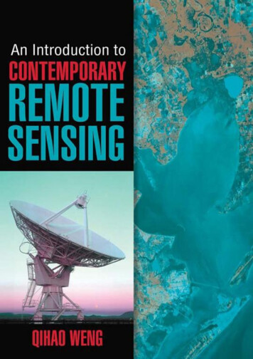
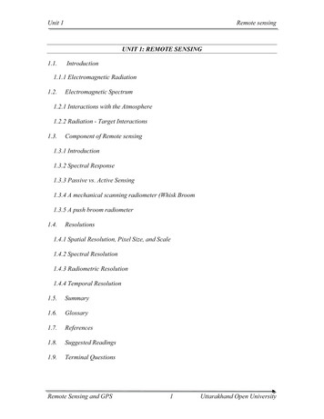
Motivations & ObjectivesThe purpose of developing such a portable sensing platform is to try to bridge the gapbetween the existing mechatronic courses and their potential benefits in industrial applications.From the course development standpoint, the portable sensing platform designed in this project isto provide new lecture and lab materials that are closely related to the modern mechatronic areas.The integration of the microcontroller units with other intelligent sensors focuses on theapplication aspects of the courses will help students gain more hands-on experiences andbeneficial to their career choices. From the research perspective, the developed portable sensingplatform can be viewed as a prototype of testbed that can be used for verification of researchideas and algorithm developments.It is also the hope of the authors, this proposed portable Lidar platform can be used forapplied engineering projects of microelectronics for faculty in better teaching and learning orfurther research project that will be interested in the academic community. Currently, there are15 different institutions that have fully adopted the previous design: “uC Training System” wherethere are strong interests in adding this prototype design to their engineering projects [3, 4].(Please see www.ucdistancetraining.org).In the long term objectives, the developed sensing platform will be used to solve a varietyof engineering problems. To name a few, one can see the potential application of the device forthe congestion problems in city, highway, and tunnel during the traffic hours or emergentconditions. There will be a systematic approach in using multiple intelligent Lidar platforms toform a real-time network with customized protocols to inform, suggest, or even control thevehicle speed without fully stopping the vehicle. By doing so, the traffic congestion becomemanageable to achieve both time and fuel efficiency. The other possible application is to targetthe locomotive safety controls that use this real-time network data with proper repeaters inextended distance condition and intelligent communication protocols to avoid collision andeventually save life and properties. Other applications may include the use of the sensingplatform in Unmanned Aerial Systems (UAS) to assist the tasks of navigation, autonomouslanding and taking off in various demanding situations.There are other available modules such as Arduino or Raspberry Pi can be used in asimilar format as this proposed platform designs. But the disadvantages are: (1) those modulesuse pre-made functions that are available for download, where they lack flexibility in customizeddesign in teaching and training students for necessary skills in the microelectronics jobs market,(2) the security issues where everyone can gain access of the functions to interfere in thecommunications, and (3) the deficiency of power consumption and management abilitiescompromising the portability of the intended applications.System Framework of Lidar-based Sensing PlatformFigure 1 shows a system framework for the proposed portable embedded sensingplatform which consist of the modules of microcontroller unit, portable interface, Lidar sensors,and information storage & display. The information flow goes between microcontroller, portableinterface, and Lidar sensors. The communication between the micro-controller and Lidar sensorsis conducted through a portable interface that is designed in this project. The microcontroller unitwill initialize the communication by setting up the appropriate configurations of the Lidarsensors (e.g., the data rate). After the initialization, the microcontroller unit will request the dataof distance and angles from the Lidar sensors and those data will be sent through the portable
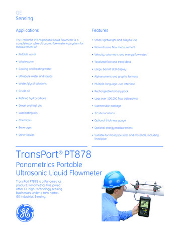
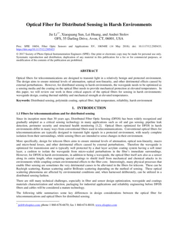
interface. After receiving the data information, the microcontroller unit will determine whetherthe information from the Lidar should be displayed on LCD or stored in a memory stick. Thedecision will be based on certain applications. For example, if the application is aimed atobstacle detection and avoidance. Then the microcontroller unit will process the information ofthe distance and angles to determine whether the distance is below a specified safe threshold. Ifthe safety threshold is violated, then the microcontroller will disclose the message of safetywarning or obstacle detected on LCD. If the safety threshold is not violated, the data of distanceand angles will be kept in the memory stick that is also connected to the microcontroller throughthe portable interface.Figure 1. Portable Embedded Sensing PlatformIn the subsequence, each module will be described in details by discussing its physicalfeature and functionality in the sensing platform. The design, evaluation and test of the portableembedded sensing platform are completed based on the undergraduate senior project supervisedby the faculty.Microcontroller Unit and USB Host ControllerThe microcontroller unit used in this project is the TI Tiva C Series LaunchPad which hasbeen widely used in different applications. The platform is selected based on its flexibility, andavailability of free development software and portability to program without special hardware.Figure 2 demonstrates the launchpad board with the TM4C123GH6PMI microcontroller. The TImicrocontroller is a 32-bit ARM Cortex M4-core that uses less memory and has faster speed thanpure 32-bit [3]. It is an inexpensive microcontroller with comparable performance in terms ofsignal processing ability. In this project, we will leverage the capability of such microcontrollerunit to design portable interface for smart sensing applications. In particular, the hardware andsoftware interface will be designed based on the communication functionality and featuresprovided by the TI launchpad. The TI launchpad has a variety of hardware interfaces for externaldevice connections. The commonly used ones are USB, Synchronous Series Interface (SSI), SPIand UART. The launchpad comes with well-established software supporting those interfacesdesign. For instance, the TivaWare for C Series software provides the USB library and theperipheral driver library that enables programming and debugging in different levels. In thisproject, we will adopt the UART and SPI for communication between devices.
Figure 2. TI Tiva C Series LaunchPadAs discussed in previous section, the first objective of this project is to establish thecommunication between the microcontroller in the Tiva LaunchPad and the Lidar sensors.Unfortunately, the TM4C123GH6PMI microcontroller in the Tiva LaunchPad does not have theability to serve as an independent USB host, but only possible to function as an USB device.Indeed, the TivaWare software provides the USB library that supports various classes of USBDevice functionality including the HID mouse device class, HID keyboard device class and theMass Storage device class. However, none of these existing software support the USB hostfunctions, which is critical for the communication between microcontroller and Lidar sensors.Due to the lack of functionality support in the Tiva software, this project selects a USB hostcontroller named VDIP1 module, to address the USB interface supporting issues. The VDIP1Vinculum VNC1L is a USB host controller module developed by Future Technology DevicesInternational (FTDI) Ltd and it was the first FTDI’s Vinculum family designed for providingfunctions of USB host interface and data transferring as well as the USB device classes [7]. TheVDIP1 module handles the data structure by communicating through UART, SPI or parallelFIFO interfaces via simple command set. The flexibility and simplicity features of this moduleprovides an effective and efficient means for those devices that do not have USB host capability.Moreover, the VDIP1 module is able to support up to two USB devices simultaneously. Asshown in Figure 2, one of the USB ports is physically constructed and can be directly connectedto the devices while the other one can be constructed by adding external circuits. The externalcircuit configuration of a second USB port can be found at Figure 6.1 in the data sheet of theVDIP1 module [7]. In this project, only one of the USB ports will be used to connect to the Lidarsensor.VDIP1 module: Figure 3 illustrations the schematic connection between the VDIP1module and the microcontroller unit in the Tiva Launchpad. Specifically, the VDIP1 module has24 pin outputs consisting of 13 regular I/O pins (AD and AC) and 11 function pins. The moduleprovides on-board jumper pin that takes the AC5 and AC6 as inputs selecting differentcommunication modes. There are three modes that can be selected for the communication
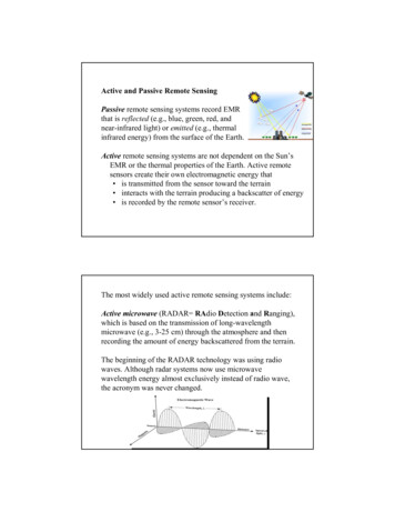
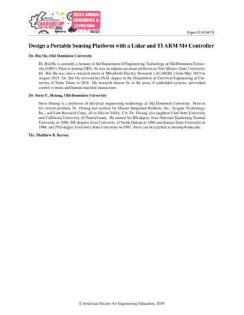
between the module and external USB devices. The serial UART mode is selected if both theinput pins AC5 and AC6 are either high or low. The SPI mode is selected if the input AC5 is setto be low and AC6 is set to be high. The parallel FIFO mode is activated if the input AC5 is highand the input AC6 is low. After setting the appropriate communication mode, it can be interfacedthe appropriate I/O pins to the MCU for different applications. In this paper, we focus on the useof UART mode for communication and other modes can be set up similarly. Once the serialUART mode is selected, the pins of AD0 and AD1 serve as the ports for receiving andtransmitting data, respectively.TI Tiva Launchpad: the MCU in the Tiva Launchpad provides serial connectivity ofeight UART units, six I2C units and four SPI units. From the MCU side, the UART unit can beactivated by configuring the appropriate General Purpose Input/Output (GPIO) pins. Forinstance, in the Tiva Launchpad, the GPIO pins PD6 and PD7 can be configured as the receiveand transmit sides of the UART module 2. The mappings of GPIO pins to the other seven UARTmodules can be found at Table 14-1 in the Tiva MCU datasheet [3].In this project, the UART module 2 of the MCU is used for the connection to the UARTof VDIP1 module. In particular, as shown in Figure 3, the pin PD6 of the UART2 receiver isconnected to the pin AD0 of the UART transmitter in the VDIP1 module. The transmitter pinPD7 of the MCU is connected to the receiver pin AD1 of the VDIP1 module. After poweringboth of the modules with 5 V power supply and grounding both modules, the hardwareconnection between the TI MCU and USB host controller VDIP1 module is established [7]. Thedata exchange between MCU and VDIP1 model can be done in two different modes through theUART interface. The first mode is called the “command monitor mode” which provides aninterface for the MCU to read and send the data. When the VDIP1 module works under thecommand monitor mode, a prompt of “D:\ ” will be sent back to the MCU indicating that theVDIP1 module is ready to execute any commands being sent [8]. The second communicationcode is called “data mode” under which the data is directly passed between the devices withoutchecking the status. As described in the firmware manual of VDIP1, user can choose thecommand mode or data mode by setting the pin AD4 to be either high (command mode) or low(data mode). Then, the AD5 severs as an output for the mode status with its high logic staterepresenting the command mode and low logic state representing the data mode.
Figure 3. Hardware Connection Between TI Tiva C Series LaunchPad and VDIP1 ModuleOnce the communication channel between VDIP1 module and MCU is established, weare ready to connect the Lidar sensor to the USB port of the VDIP1.Lidar SensorsThe Lidar sensor that we are using in this project is Hokuyo URG-04LX-UG01 scanningLaser Rangefinder with the USB interface. This Lidar sensor is suitable for indoor applicationswith short distance range (maximum of 5 meters). The market price for this type of Lidar isaround 1,040.00 and the detailed specifications can be found in the official ?serial 166. The URG-04LX-UG01 Lidar is ableto provide the measurement of distance with accuracy of 30 mm and angles with respect to its270 degrees view angles [9]. It has been used as intelligent sensors for a variety of applications,to name a few, the navigation of mobile robots and flying quadrotors, due to its light weight andlow-power consumption. However, many of these applications rely on the USB connection to thePC or laptop. For the applications of quadrotors, the Lidar is often integrated with costly andadvanced MCUs that comes with USB host controller. These MCUs often have well-developedmodules that are not easy to be customized into different needs. Thus, from research’sstandpoint, it is important to develop a portable and customizable sensing platform forapplications with limited budgets. This project takes the first step to design the portable andcustomizable interface between the MCU and URG-04LX-UG01 Lidar. From the coursedevelopment’s perspective, the developed sensing embedded system provides a platform thatbenefits the development of new multidisciplinary courses in the mechatronic areas.The Lidar sensor sends the data of distance and angles to the MCU through the USB hostcontroller. The data transmission protocol must satisfy the communication specifications that aredefined to comply with URG sensor command system in SCIP ver2.0 or SCIP ver1.1 [10]. Thecommunication protocol specifies commands and data format that need to follow to ensuresuccessful data transmission. The commonly used commands include “MD/MS” and “GD/GS”where the “MD/MS” is a sensor data acquisition command sent from host (MCU) to the sensorrequesting three character (MD) or two character data (MS) and the command “GD/GS”
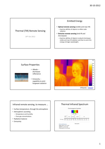
represents the request of the latest data to the host. Upon receiving the commands, the sensorencodes the data by adding the hex number 30H to each 6-bits binary raw data and sends theencoded data to the host. Each data is associated with a time stamp with 1 millisecond resolution.The time stamp represents the starting point of the scanning.Based on the communication protocol specifications, one of the major developments inthis project is the design of software interface between MCU and Lidar sensor. The softwareinterface consists of a group of APIs that serve for different functionalities. These functionalitiesinclude the initialization of the UART, function configuration of the GPIOs, error handling andresponse function, read/write data, distance acquisition function, angle acquisition function andthe obstacle detection function. Details of these APIs will be discussed in the next section.Portable Interface DesignThe objective of design a portable interface is to ensure that the developed sensingplatform can transferrable in different applications. The key idea for the portable design lies indefining and implementing modularized APIs that perform different functionalities of the systemin a hierarchical structure. Figure 4 displays a hierarchical structure of the portable interfacedesign which is comprised of three different layers. The first layer called “initialization/dataacquisition” directly communicates with the hardware interface of the MCU, VDIP1 and Lidarsensors. The first group of the APIs in the first layer involve initialization functions that aredefined to setup the appropriate parameters for all the three modules to be ready for use. Withinthe initialization functions, the configuration of the hardware parameters, such as GPIO pins,UART module, the clock frequency, baud rate, command mode as well as enabled interrupts.The second group of APIs in the first layer is the Read/Write functions which read the datacoming from the FIFO buffer of the MCU as well as write commands to the FIFO buffer. Theread/write functions handle the data stream through the UART ports, which are embodied in theinterrupt functions. The last group of APIs in the first layer is the error handling functions whichresponds and displays specific messages explaining the presence of certain errors, such as “thedevice not connected” or “Invalid Commands” which are commonly encountered but difficult todetect in the debugging process. On one hand, the APIs in the first layer are called by the secondlayer to handle complex requests and commands, such as “take the measurements of distance andangles every 100 ms”. On the other, the second layer receives the data from the read function inthe first layer and packets them for the use of third layer. Thus, there are data stream exchangedbetween the first layer and the second layer.The second layer of the smart sensing APIs implements the functionality of informationextraction. Here the information extraction means that the information of distance and angle isextracted out of the data received from the UART FIFO buffer. As discussed in the previoussection, the packet sent from Lidar sensor is comprised of distance information as well as thecontrol information. The distance information is encoded by adding the hex number 30H. Toextract the distance and angle information, the APIs in the second layer need to do the followingtwo steps. The first step is to extract the distance information from the packet by removing thecontrol information. The second step is the decoding of the distance information by subtractingthe encoded data. The extracted information is requested by the third layer for applications. Inthis project, the application focuses on the obstacle detection which determines the presence ofobstacles by checking whether the distance measurement is below a pre-defined threshold. Thus,the third layer involves the APIs that implement the obstacle detection and mapping algorithms.
Figure 4. Hierarchical Scheme of the Portable Interface DesignThe hierarchical structure of the APIs enables the flexible and portable implementation ofthe smart sensing platform that can be used in different mobile applications. One of the examplesis the navigation task of the mobile robot where the obstacle detection algorithm used in thesmart sensing platform can provide safety guarantee when the robot navigates through the indoorenvironment. Moreover, the same platform can also be used to assist the tasks of landing andtaking off for UAV systems. The smart sensing APIs are defined and implemented using the Ccodes that are based on the libraries provided by TivaWare [2]. The TI Code Composer Studio(CCS) [6] is used to write and debug the designed APIs and the test results are printed in the PCterminal or LCD module.Information Store & DisplayThe information coming out of the smarting sensing APIs can be stored in memory sticksor displayed on the LCD. Whether the information should be stored or displayed depends on thespecific applications. For instance, the obstacle detection application requires that warningmessages must be displayed in LCD whenever an obstacle is detected within a safe region. Whenthe obstacle is absent in a nearby environment, the data of the distance and angle should bestored in a memory stick. The memory stick can be connected to the second USB port of theVDIP1 USB host controller.Prototype of Portable Sensing PlatformIn this project, the portable sensing platform is built on the uC Training System, whichhas been developed by one of the authors under previous funded NSF projects [3]. The platformhas been successfully used in the lecture and lab classes at different universities and collegesincluding Old Dominion University, Farmingdale State College (FSC). All the available courseand lab modules are available at www.ucdistancetraing.org.It is the authors’ intention that these developments will be used as future teaching tools.Figure 5 shows a prototype of a portable sensing platform where the selected TI Tiva C SeriesLaunchpad is placed in the socket and the VDIP1 USB host controller is inserted into thebreadboard of the uC Training System. It has been demonstrated in previous projects that the uC
Training System is able to integrate different types of MCU including the PIC as well as the LCDdisplay unit. The Lidar sensor is connected to the main USB port of the VDIP1 module. Thejumpers are used to connect the appropriate pins of the MCU and VDIP1 module as discussed inprevious sections. The main objective of this project is to demonstrate the customizability andportability of the sensing platform. The ultimate goal is to integrate all the modules (MCU andUSB host controller) into one single board that can be applied to different applications. Theprototype of the sensing platform demonstrated in Figure 5 is a prototype of the concept.Figure 5. The Portable Sensing Embedded System Using the uC Training SystemObstacle Detection DemonstrationRegarding the application of the developed sensing platform, this project focuses on thedemonstration of obstacle detection tasks. The portable sensing system shown in Figure 5 will beused for the demonstration and the platform will be further revised for detecting differentobstacles. The LCD display unit will disclose the information about the presence of obstacles interms of the distance and angles. If the distance of the obstacle is too close to the platform, theLCD will display warning message informing the system that there might be a potential collisiongiven the distance measured by the Lidar sensor.Potential Teaching & Research DevelopmentThe purpose of this project is to introduce a portable sensing platform that can be used forpotential teaching and research development. From the teaching standpoint, the platformprovides a foundation under which new or existing courses can be developed and improved tomeet the new challenges in the industry. This is especially important for the mechatronic areas
where devices with portable and intelligent capabilities are the most desirable features in variousapplications. The developed platform can also be used in senior project design or capstoneproject for undergraduate students who want to obtain hands-on experience of working withmicrocontroller with intelligent sensors. From research’s standpoint, the smart sensing platformcan sever as a testbed that is used for verification and experimentation of the proposed researchideas. The potential research directions may include the exploration of the cybersecurity issues inusing the Lidar sensor and the algorithm development of 3D mapping using the Lidar sensor.Conclusion and Future WorkThis project is funded by Navy research and development (ONR Award N00014-18-12682) that also involved undergraduate students’ capstone projects, which lead to meet navalcurrent & future workforce development needs. All the Lidar sensors are in the price range of 1,000 to 5,000 depending on its power, speed, and detecting distance. Without the externalsupports of this project, it is impossible to bring this portable sensor platform designs into theclassroom for teaching and learning.This paper introduces a portable smart sensing platform where the TI Tiva MCU is ableto communication with the URG-04LX-UG01 Lidar through the VDIP1 USB host controller.The focus of this paper is the design of portable interface enabling data exchange between MCUand Lidar sensor. The hierarchical structure of the portable interface allows the implementationof complex tasks and commands in MCU. Moreover, this project shows a prototype of theportable smart sensing platform that is built upon the well-developed uC training system. Thedemonstration of the obstacle detection using the smart sensing platform will provide a proof ofconcept for our ultimate goal of integrating all modules in one single board. In the future, we willcontinue to explore the portable interface design for Lidar sensor with other interfaces, such asEthernet. This can further lead to the development of new microcontroller courses based on theportable sensing platform. From education’s perspective, it is important and interesting to seewhether the learning performance of the students can be improved by using the platform.References1.A. Malinowski and H. Yu, “Comparison of embedded system design for industrial applications,” IEEE Trans.Ind. informatics, vol. 7, no. 2, pp. 244–254, 2011.2. Texas Instruments, Tiva C Series TM4C123G LaunchPad Evaluation Board, User’s Guide, 2013.3. LMS, January 30, 2018. [Online]. Available: http:// http://www.ucdistancetraining.org/moodle/4. S. Hsiung, J. Ritz, M, R. Jones, J. Eiland, “Design and Evaluation of a Microcontroller Training System forHands-on Distance and Campus-Based Classes.” Journal of Industrial Technology 2010; 26(3): 2-8.5. Texas Instruments, Tiva Ware Peripheral Driver Library, User’s Guide, 2016.6 CCS, Texas Instrument Code Composer Studio, January 30, 2018. [Online]. Available:http://www.ti.com/tool/ccstudio7. Future Technology Devices International Ltd., VDIP1 Vinculum VNC1L Module Datasheet, 2010.8. Future Technology Devices International Ltd., Vinculum Firmware, User Manual, 2008.9. HOKUYO, Range-Finder Type Laser Scanner URG-04LX-UG01 Specifications, 2005.10. HOKUY
Figure 1 shows a system framework for the proposed portable embedded sensing platform which consist of the modules of microcontroller unit, portable interface, Lidar sensors, and information storage & display. The information flow goes between microcontroller, portable interface, and Lidar sensors.