Transcription
C H A P T E R3Planning the IP Telephony NetworkIn this ChapterThis chapter consists of the following sections: Evaluating and Documenting the Existing Data Infrastructure Evaluating and Documenting the Existing Telecom Infrastructure Evaluating and Documenting the Existing Power/Cabling Infrastructure IP Telephony Availability Requirements Planning for WAN Deployments Operations and Implementation PlanningRelated Information Data Sheet: Cisco VoIP Readiness Net Audit Planning for Migration to IP mkt/sup/ent/avvid/nadit ds.htm Cisco IP Telephony Network Design ct/voice/ip tele/index.htm Westbay Engineers Limited Home Pagehttp://www.erlang.com APC Home Pagehttp://www.apcc.com Cisco IP Telephony Power Protection avvid/solutions/powerpro.htmlEvaluating and Documenting the Existing Data InfrastructureOrganizations need to evaluate their existing data infrastructure to help determine upgrade requirementsfor the IP Telephony solution. You may need to provide infrastructure for additional bandwidth,consistent performance, or higher availability required for the converging environment. This sectiondescribes both LAN and WAN requirements.Cisco Technical Solution Series: IP Telephony Solution GuideVersion 2.13-1
Chapter 3Planning the IP Telephony NetworkEvaluating and Documenting the Existing Data InfrastructureYou should document and evaluate the existing data infrastructure in terms of: New voice performance requirements Availability requirements Feature requirements Potential network capacity or impact.The required information for this includes network maps, device inventory information, and networkbaseline information. Analyzing these areas will help you understand the data network upgraderequirements needed to support IP Telephony and basic network availability, performance, and featurerequirements.To evaluate voice performance requirements, review the device inventory, network design, and baselineinformation. Links and devices should have sufficient capacity for the additional voice traffic. You mayneed to upgrade links with high peak or busy hour utilization. Target devices with high CPU utilization,high backplane utilization, high memory utilization, queuing drops, or buffer misses for additionalinspection and potential upgrade. Peak utilization characteristics in the baseline will be valuable indetermining potential voice quality issues.To evaluate availability requirements for the IP Telephony network, review the network topology, featurecapabilities, and protocol implementations. Review redundancy capabilities of the network to ensure youcan meet availability goals with the current network design (or a new design) recommended for IPTelephony.To evaluate current feature capabilities of the network, evaluate device characteristics including achassis, module, and software inventory. This will be useful in determining IP Telephony featurecapabilities in the existing environment.You should also evaluate overall network capacity and impact to ensure that the network will meetoverall capacity requirements and that there will be no impact on the existing network and applicationrequirements. You should evaluate the network baseline in terms of the impact from IP Telephonyrequirements. You may need to add more CPU, memory, bandwidth, or features to ensure you meet bothIP Telephony and existing network requirements.NoteCisco can provide an IP Telephony readiness audit that provides the recommended baselineinformation.LAN/Campus EnvironmentWe recommend a LAN/Campus analysis for all LAN environments involving any of the four IPTelephony deployment models that include: Single site Networked with PSTN Multi-site with centralized call processing Multi-site with distributed call processing.The LAN/Campus infrastructure analysis determines infrastructure and bandwidth issues that will affectIP Telephony voice quality and availability. You should collect the following types of information forthe LAN/campus infrastructure analysis: LAN/campus topology IP addressing planCisco Technical Solution Series: IP Telephony Solution Guide3-2Version 2.1
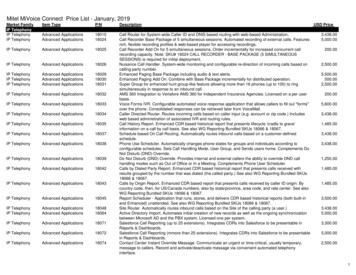
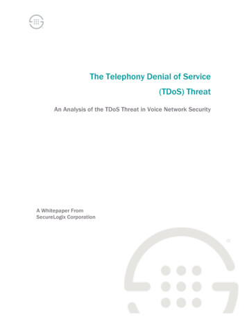
Chapter 3Planning the IP Telephony NetworkEvaluating and Documenting the Existing Data Infrastructure Location of TFTP servers, DNS servers, DHCP servers, firewalls, NAT (Network AddressTranslation) gateways, and PAT (Port Address Translation) gateways Potential location of gateways and CallManager clusters Protocol implementation including IP routing, Spanning Tree, VTP, IPX, and IBM protocols Device analysis including software versions, modules, ports, speeds, and interfaces Phone connection methodology (direct or daisy chain) Baseline showing network and resource control plane useLAN/Campus TopologyYou normally build LAN/campus infrastructures using a hierarchical access, distribution, and coremodel. One or two of these layers may be collapsed into smaller LAN/Campus environments. However,in general, you will have a standard deployment model with a standard distribution and coreconfiguration. Read the Campus Network Design document to review Cisco’s recommendations for ahigh availability campus design. This document can be found at the following n/campus index.html.You should create a simple map, such as Figure 3-1, that describes the layers, devices, media, and portspeeds. The topology map should also show the location of TFTP servers, DNS servers, DHCP servers,firewalls, and gateways.Review the following LAN/campus topology issues: Available average bandwidth Available peak or burst bandwidth Resource issues that may affect performance including buffers, memory, CPU, and queue depth Network availability IP phone port availability Desktop/phone QoS between user and switch CallManager availability Network scalability with increased traffic, IP subnets, and features Backup power capability LAN QoS functionality Convergence at Layers 2 and 3Cisco Technical Solution Series: IP Telephony Solution GuideVersion 2.13-3
Chapter 3Planning the IP Telephony NetworkEvaluating and Documenting the Existing Data InfrastructureFigure 3-1LAN/Campus TopologyGigabitethernetdistributionlinks6500 with IP routingand no 802.1q or VLANsGigabitethernetcore links5500 with dual RSMVLAN support foraccess/distribution10 megabit ethernetuser access100 megabit ethernetCatalyst 5500'sserver accesswith 1/2 user VLANper device48137100 megabitethernetuplinksIP Addressing PlanReview the following IP addressing plan and implementation characteristics: Phone IP addressing plan Average user IP subnet size use for the campus Number of core routes IP route summary plan DHCP server plan (fixed and variable addressing) DNS naming conventionsPotential considerations with IP addressing include: Route scalability with IP phones IP subnet space allocation for phones DHCP functionality with secondary addressing IP subnet overlap Duplicate IP addressingLocation of Servers and GatewaysConsider the location (or potential location) of servers and gateways prior to implementation andidentify them in the LAN infrastructure planning phase as much as possible. Investigate other issues laterto help ensure that service availability is consistent across the LAN infrastructure and for multiple sites.You should identify gateway and server network locations for the following: TFTP servers DNS servers DHCP serversCisco Technical Solution Series: IP Telephony Solution Guide3-4Version 2.1
Chapter 3Planning the IP Telephony NetworkEvaluating and Documenting the Existing Data Infrastructure Firewalls NAT or PAT gateways CallManager location Gateway locationInvestigate these issues after you determine the location: Network service availability Gateway support (in conjunction with IP Telephony solution) Available bandwidth and scalability Service diversityProtocol ImplementationInvestigate overall protocol uses to determine IP Telephony scalability and any potential IP Telephonyavailability issues or additional protocol service issues. Review the following areas for the protocolimplementation analysis: IP routing including protocols, summarization methods, NBMA (non-broadcast media access)configurations, and routing protocol safeguards Spanning Tree configuration including domain sizes, root designation, uplink fast, backbone fast,and priorities in relation to default gateways HSRP configuration VTP and VLAN configuration IPX, DLSW, or other required protocol services including configuration and resource usageYou should review the following issues in relation to protocol implementation: Protocol scalability Network availability Potential impact on IP Telephony performance or availabilityDevice AnalysisAnalyze the existing network devices to help identify hardware and software issues associated with theIP Telephony deployment. Many devices may not have the desired control plane resources, interfacebandwidth, QoS functionality, or power management capabilities. The following table displays deviceattributes that may be important: Device (type and product ID) Software version(s) Quantity deployed Modules and redundancy Services configured User media and bandwidth Uplink media and bandwidth Switched vs. shared mediaCisco Technical Solution Series: IP Telephony Solution GuideVersion 2.13-5
Chapter 3Planning the IP Telephony NetworkEvaluating and Documenting the Existing Data Infrastructure Users per uplink and uplink load sharing/redundancy Number of VLANS supported Subnet size, devices per subnetNetwork BaselineYou can use a network baseline of the existing campus/LAN infrastructure for IP Telephony capacityplanning. This will help determine potential voice quality issues and the impact to the existingenvironment. Measure the following characteristics as part of the baseline: Device average and peak CPU Device average and peak memory Peak backplane utilization Average link utilization (prefer peak hour average for capacity planning) Peak link utilization (prefer five minute average or smaller interval) Peak queue depth Buffer failures Average and peak voice call response times (before IP Telephony implementation)Many different individuals and support organizations recommend different acceptable threshold valuesfor these measured baseline issues. Remember that IP Telephony requires consistent performance andquality; therefore, all of the areas should be below safe recommended threshold values at all times. Usethe following general guidelines on threshold issues: CPU—A requirement for all background processing in addition to some traffic processingrequirements. Background processing includes route updates, keepalives, network management, andother critical processes for keeping the network up and stable. During stressful network times, suchas route convergence or link flapping, significant CPU will be used to ensure the network remainsstable and intact. Because significant CPU can be used during stress situations, a good rule of thumbis 50% peak CPU and 30% average CPU. Memory—Like CPU, main memory is used for background processing and traffic processing. Andlike CPU, significant amounts of memory can be used for a processing during link flap conditions,routing changes, and cache changes. Because significant changes can occur in memoryrequirements, a good rule of thumb is 50% peak and 30% average. Backplane Utilization—Can be a major issue in some devices if the port speed and density is higherthan the available backplane capabilities. Backplane utilization over 50% may also indicate someport queuing or dropped traffic for trunks that have less bandwidth than the sum of all downstreambandwidth. Link Utilization—Critical to IP Telephony deployments because of VoIP performance and jitterrequirements. First, remember that SNMP thresholds for peak utilization are still mainly done forfive minute intervals. A good rule of thumb is to increase bandwidth utilization 40% above the fiveminute value to determine a true measure of peak utilization over the five minute average. Averagelink utilization may also be useless over time if peak-critical traffic occurs during a shorter intervalof one hour. The telecom community thinks in terms of “busy hour” traffic. If you perform capacityplanning using this busy hour utilization, then data network managers can consistently meet bothvoice and data requirements.To some extent, QoS capabilities at level II and level III will help minimize the need for significantbandwidth headroom. However, voice will add significant volume to the network and care should betaken to ensure that data traffic is not starved. Network designers also like to ensure that moreCisco Technical Solution Series: IP Telephony Solution Guide3-6Version 2.1
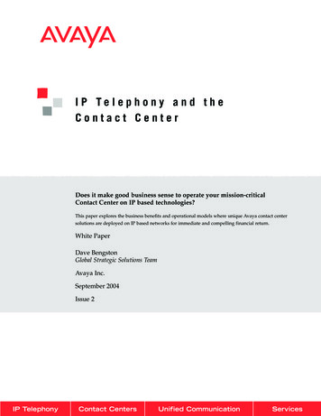
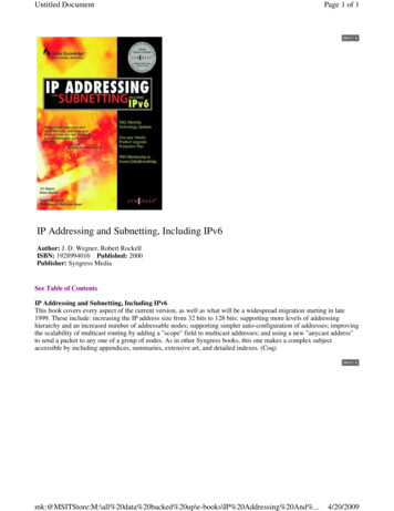
Chapter 3Planning the IP Telephony NetworkEvaluating and Documenting the Existing Data Infrastructurebandwidth is available towards the core to help minimize or eliminate significant or criticalcongestion problems. Therefore, care should be taken for all core network links that have peakutilization in excess of 50% and average utilization above 30%. VoIP will likely work if it is higher,but there will be more opportunity for potential intermittent bandwidth problems that will first affectthe critical voice traffic.Note Queue Depth—Indicates link congestion. Any transmit queues that experience any volume at allindicate that traffic is waiting. This directly impacts voice jitter and delay and indicates that linkutilization is exceeding a peak recommended value. Buffer Failures—Indicates a temporary inability to perform control processing in the device andshould be investigated in terms of overall network health. Some buffer failure issues could impactVoIP quality and should be investigated.Cisco can provide a network baseline called the IP Telephony readiness Net /sup/ent/avvid/nadit ds.htm).WAN EnvironmentWe recommend a WAN infrastructure analysis for multiple-site WANs with distributed call processingor multi-site IP WANs with centralized call processing. The WAN analysis determines infrastructure andbandwidth issues that will affect IP Telephony quality and reliability. You should collect the followinginformation for the WAN environment analysis:Note WAN topology Location of gateways and servers WAN protocols Existing QoS requirements Device Analysis including software versions, modules, ports, speeds and interfaces WAN baselineReview “LAN/Campus Environment” for information on location of gateways, IP addressing plan,and protocol implementation. We recommend some LAN analysis for all WAN sites supporting IPTelephony.WAN TopologyYou normally build WAN topology infrastructures using a hub and spoke model, meshed multi-sitemodel, or a combination of both. You should create a WAN diagram showing potential IP Telephonysites, WAN devices, remote LAN devices, interface types, and bandwidth. The map should show thelocation of DNS servers, DHCP servers, firewalls, gateways, and potential CallManager locations. SeeFigure 3-2 for a sample WAN topology.Review the following WAN topology issues: WAN availability, including bandwidth redundancy and resiliency WAN design or topology issues that may affect IP Telephony quality or performanceCisco Technical Solution Series: IP Telephony Solution GuideVersion 2.13-7
Chapter 3Planning the IP Telephony NetworkEvaluating and Documenting the Existing Data InfrastructureNoteThe Cisco IP Telephony Network Design Guide currently recommends a hub and spoketopology until call admission control using RSVP (Resource Reservation Protocol) iscompletely available. This document can be found at the following roduct/voice/ip tele/index.htm. WAN scalability with increased traffic, IP subnets, and features Bandwidth and WAN service expectations Existing QoS requirements (see the “Designing for LAN/WAN QoS” section on page 4-2 for moreinformation.)WAN Infrastructure1025port/512CIR7500router100Frame relaycloud1025port/512CIR2megabit/secport 1024 CIRCall managerDNS serverDHCP server1025port/512CIR3640router2948G10LAN switchmegabit/sec3640router2948G10LAN switchmegabit/sec3640router2948G10megabit/ LAN switchsec48139Figure 3-2Location of Servers and GatewaysConsider the location (or potential location) of servers and gateways in the WAN prior to implementationand identify them in the WAN infrastructure planning phase as much as possible. Identify the followinggateway and server network locations: TFTP servers DNS servers DHCP servers Firewalls NAT or PAT gateways CallManager location Gateway locationYou should investigate the following issues after you determine the location: WAN outage impact and service diversity Gateway support (in conjunction with IP Telephony) Available bandwidth and scalabilityCisco Technical Solution Series: IP Telephony Solution Guide3-8Version 2.1
Chapter 3Planning the IP Telephony NetworkEvaluating and Documenting the Existing Data InfrastructureWAN ProtocolsYou should investigate WAN protocols for issues that may impact IP Telephony quality or issues thatmay be affected by additional voice services. In many cases, the WAN may require further optimizationto better support IP Telephony traffic. NBMA (non-broadcast multiaccess) environments may also besusceptible to protocol issues and overall reliability that can affect voice quality. Investigate thefollowing specific issues: WAN IP protocol implementation and protocol overhead IP multicast implementation Carrier Service subscription rates including port speed, committed information rates, and expectedperformance NBMA protocol issues affecting voice quality and performance Other protocol overhead, including IPX and SNAAnalyze the following areas after investigating WAN protocol issues: Protocol optimization WAN scalability with increased traffic Expected network convergence with redundant topologies Carrier reliability and quality expectations with WAN protocolsExisting QoS RequirementsYou should evaluate existing WAN QoS requirements to determine compatibility with Voice QoSrequirements. You should identify applications and performance requirements, including applicationperformance, burst requirements, and batch requirements. Investigate the following areas: Existing WAN QoS configurations Critical application requirements, including raw performance, burst bandwidth, and batchbandwidth WAN call admission controlDevice AnalysisAn analysis of existing network devices in the network helps identify hardware and software issuesassociated with the IP Telephony deployment. Software versions are important to determine QoSrequirement compatibility. You can also use this information to create a network reliability path analysisto help determine potential network availability. The following table displays device attributes that maybe important: WAN Devices Software Version(s) Remote LAN Devices Software Version(s) Quantity Deployed Modules and Redundancy Services ConfiguredCisco Technical Solution Series: IP Telephony Solution GuideVersion 2.13-9
Chapter 3Planning the IP Telephony NetworkEvaluating and Documenting the Existing Telecom Infrastructure WAN Media/Bandwidth LAN Media/Bandwidth Switched vs. Shared Media User and IP Addressing per WAN SiteWAN BaselineYou can use a WAN baseline of the existing WAN and WAN site infrastructure for IP Telephony capacityplanning. This will help determine potential voice quality issues and the impact to the existingenvironment. Measure the following characteristics as part of the baseline: Device average and peak CPU Device average and peak memory Average link utilization (prefer peak hour average for capacity planning) Peak link utilization (prefer five minute average or smaller interval) Peak queue depth Buffer failures Average and peak voice call response times (before IP Telephony implementation)See the “Network Baseline” section on page 3-6 for specific guidelines for measuring thesecharacteristics.Evaluating and Documenting the Existing TelecomInfrastructureYou need to evaluate the existing Telecom infrastructure to help determine IP Telephony requirements.Perform this analysis for all sites implementing VoIP technology to determine the appropriatedeployment model. IP Telephony supports the following deployment models: Single-site deployment Multiple single-site deployments interconnected via PSTN Distributed IP Telephony sites with centralized call processing Distributed IP Telephony sites with distributed call processingThe Telecom infrastructure analysis examines the products, services, and features used in the existingtelecom environment including: PBX systems and locations Voice mail systems and locations Key systems PBX inter-connectivity Phone requirements PSTN trunking Voice mail trunking Site-to-site trunkingCisco Technical Solution Series: IP Telephony Solution Guide3-10Version 2.1
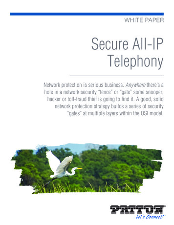
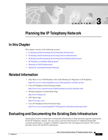
Chapter 3Planning the IP Telephony NetworkEvaluating and Documenting the Existing Telecom InfrastructureThe analysis will then help determine the IP Telephony design criteria. You should examine thefollowing issues: Existing PBX topology, including voice mail servers PBX and Key Systems Voice mail system Voice trunking Phones per site and phone features Existing dial plan Fax requirementsExamining the Existing Telecom TopologyThe existing Telecom topology includes the location and internetworking connectivity for PBX systems,key systems, and voice mail servers. The topology should include the location of these devices and thetrunks between systems used for connectivity. Trunking may include site-to-site trunks, PSTN trunks,and voice mail trunks. This section reviews the following existing Telecom topology issues: PBX system connectivity overview Trunking overviewSee Figure 3-3 for an example telecom topology showing PBX systems, key systems, and voice mailsystems:Figure 3-3Telecom TopologyRemotePBXLong distancePSTNT-1PRILocalPSTNVPNPBXT-1PRItrunks30 analogtrunksEPNPBX30 co Technical Solution Series: IP Telephony Solution GuideVersion 2.13-11
Chapter 3Planning the IP Telephony NetworkEvaluating and Documenting the Existing Telecom InfrastructureExamining PBX and Key SystemsYou need PBX and key system information to help understand current voice features and functionality.The following information will help determine required features and PBX-to-IP Telephony connectivityrequirements. PBX or KSU vendor and model Quantity and locations of PBX/KSU systems Release of software running on PBX or KSU Quantity and location of PBXs with which IP Telephony may interface Hardware models and revisions of installed cards Software features currently deployed, which may include call setup, conferencing, call transfer, callhold, call park, calling line identity, and calling party name Number of existing analog connections for each PBX or KSU and three expected to remainfollowing deployment Number of existing digital connections for each PBX/KSU and those that will remain Number and capacity of ISDN trunks connected to each PBXExamining Voice Mail SystemsYou will need the following information to determine IP Telephony compatibility and featurecapabilities: Voice mail system models and vendor Quantity and locations of voice mail systems Hardware model and revision cards of voice mail systems List of software features currently deployed with voice mail system Does the voice mail system have an SMDI interface? How is the voice mail system connected to the PBX? Is the message waiting indicator integrated into the voice mail solution?Examining Voice TrunkingUse the existing voice trunking to determine the IP Telephony gateway requirements. In general, youshould identify the trunks for voice mail, PSTN connectivity, and site-to-site trunking requirements. Inaddition, define the existing blocking factor for potential capacity issues. Cisco recommends a blockingfactor of one percent for IP Telephony trunking. You may wish to complete a traffic analysis tounderstand busy hour trunking for the various trunking applications. You can then use an Erlang-Bcalculator (http://www.erlang.com) to determine new trunking requirements. PBX vendors can normallyprovide busy hour statistics as a support service. Use Table 3-1 to help identify overall trunking:Cisco Technical Solution Series: IP Telephony Solution Guide3-12Version 2.1
Chapter 3Planning the IP Telephony NetworkEvaluating and Documenting the Existing Telecom InfrastructureTable 3-1Trunking MatrixDigital or AnalogTwo-way CallingDID TrunksDOD TrunksVoice Mail TrunksLocal PSTNTrunksLD PSTN TrunksTrunks to Site XTrunks to Site YTrunks to Site ZYou may also use the following tables for planning and configuring the gateway trunks. In some cases,you may move these trunk Demarc locations to co-exist with IP Telephony equipment. In addition, youshould document support responsibility for WAN carrier services for use in physical design documents.Cisco Technical Solution Series: IP Telephony Solution GuideVersion 2.13-13
Chapter 3Planning the IP Telephony NetworkEvaluating and Documenting the Existing Telecom InfrastructureTable 3-2PBX WAN Trunk InformationLocal Site A Name:Item No.LocalLocation ARemoteLocation BType (seebelow)Speed(Kbps)FramingCodingLocalCSU/DSUA Vendorand ModelRemoteCSU/DSUB Vendorand ModelCSU NETAConnectorType GenderCSU toDemarcCableLength (ft.)DemarcConnectorType GenderRemotePBX B SlotNo./PortNo.1.2.3.4.5.6.7.8.9.10.Table 3-3PBX WAN Trunk Cable Infrastructure InformationLocal Site A Name:Item No.PBX A Slot PBX ANo./PortConnectorNo.Type GenderPBXA/CSUCableLength (ft.)CSU ADTEConnectorType Gender1.2.3.Cisco Technical Solution Series: IP Telephony Solution Guide3-14Version 2.1
Chapter 3Planning the IP Telephony NetworkEvaluating and Documenting the Existing Telecom InfrastructureTable 3-3PBX WAN Trunk Cable Infrastructure InformationLocal Site A Name:4.5.6.7.8.9.10.NoteTable 3-4When ordering your DID, get a block of telephone (DID) numbers equal to or greater than the numberof devices (phones, virtual phones, and H.323 devices such as NetMeeting) that will be connected tothe network.PBX WAN Carrier and Circuit InformationLocal Site A Name:Item No.Local Carrier A Local Carrier A Long HaulLong HaulCompany Name Circuit IDCarrierCarrier CircuitCompany Name IDRemote CarrierB CompanyNameRemote CarrierB Circuit ID1.2.3.4.5.6.7.Cisco Technical Solution Series: IP Telephony Solution GuideVersion 2.13-15
Chapter 3Planning the IP Telephony NetworkEvaluating and Documenting the Existing Telecom InfrastructureTable 3-4PBX WAN Carrier and Circuit InformationLocal Site A Name:8.9.10.ISDN PRI is a common PBX WAN trunk type. The following parameters are typically used whenprovisioning a T-1 or E-1 PRI span: Interface: ISDN Primary Rate Interface (PRI) Frame Format: Extended Super Frame (ESF) Line Encoding: B8ZS Number of B-Channels: 23 and 30 for Euro D-Channel: on channel 24th or Euro PRI it is the 16th Line Use: VoiceISDN PRI provisioning also requires a switch type to be configured for Layer 3 protocols. There are fourfamilies of switch type protocols for PRI provisioning: AT&T, 4ESS, 5ESS, NII Called NI2 (National Protocols) DMS100 and DMS 250 (National Protocols) EUROPEAN PRI Custom 5ESS IntecomECommon switch types and Layer 3 protocols include the following switch types for well-known PBXsystems: Nortel (Meridian): 5ESS Custom NOTE: Gateway must be set to NETWORK Lucent (Definity): 4ESS or 5ESS MCI: DMS 250 SPRINT: DMS 100 or DMS 250 AT&T: 4ESS Madge (Teleos) BOX: 5ESS Custom Intecom: 5ESS CustomCommon switch types and Layer 3 protocols for IXCs and inter-exchange carriers include the following: AT&T: 4ESS MCI or SPRINT: DMS250 When connecting to a local CO switch use the following: 5ESS (5E8 or 5E9) DMS 100 NIICisco Technical Solution Series: IP Telephony Solution Guide3-16Version 2.1
Chapter 3Planning the IP Telephony NetworkEvaluating and Documenting the Existing Telecom Infrastructure Hunt Sequence: Float, Flex, or Fixed Out-pulse of digits: 4 is standard, but can be from 1 to 23 digitsPhones per Site and Phone FeaturesYou will need the number of currently supported phones to properly size the CallManager platforms.You should identify phones that will convert to VoIP and potentially some analog phones for emergencyand fax backup.You should also know the required phone features, which may include the following: Speaker capability Mute Call hold Call park Call transfer Calling line identity Calling party name Multi-party conferencingExamining the Existing Dial PlanExamine the existing dial plan architecture to understand the required call routing, abbreviated dialing,and route-group features for IP telephony migration. Call routing is used for PSTN or offnet access.Features associated with call routing include: Redundant or back-up paths (transparent to the user) Emergency dialing call patterns Automatic call distribution Call blocking where individual groups or numbers have limited offnet access.Automatic call distribution allows many agents to answer calls from one published number. Callblocking is used to limit access to certain numbers such as 900 toll numbers or long distance PSTNaccess from building lobby phones. Abbreviated dialing is used to reduce the number of digits requiredfor extension calls. In many cases, local extension dialing has been reduced to 4-digit numbers.Questions for the IP Telephony deployment include: Will the organization use existing or distributed dial plans among multiple sites? Are there number ranges to be reserved for PBXs? If so, what are they? Are there number ranges to be reserved for analog phones? If so, what are they?Use the following tables to document the existing dial plan:Cisco Technical Solution Series: IP Telephony Solution G
IP Addressing Plan Review the following IP addressing plan and implementation characteristics: Phone IP addressing plan Average user IP subnet size use for the campus Number of core routes IP route summary plan DHCP server plan (fixed and variable addressing) DNS naming conventions Potential considerations with IP .