Transcription
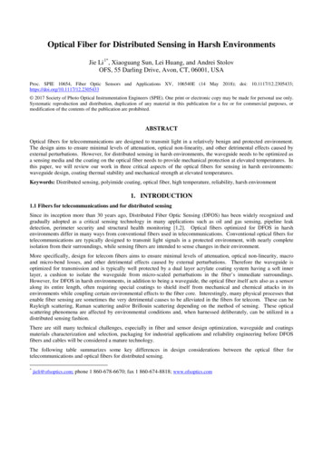
Optical Fiber for Distributed Sensing in Harsh EnvironmentsJie Li 1*, Xiaoguang Sun, Lei Huang, and Andrei StolovOFS, 55 Darling Drive, Avon, CT, 06001, USAProc. SPIE 10654, Fiber Optic Sensors and Applications XV, 106540E (14 May 2018); doi: 433 2017 Society of Photo Optical Instrumentation Engineers (SPIE). One print or electronic copy may be made for personal use only.Systematic reproduction and distribution, duplication of any material in this publication for a fee or for commercial purposes, ormodification of the contents of the publication are prohibited.ABSTRACTOptical fibers for telecommunications are designed to transmit light in a relatively benign and protected environment.The design aims to ensure minimal levels of attenuation, optical non-linearity, and other detrimental effects caused byexternal perturbations. However, for distributed sensing in harsh environments, the waveguide needs to be optimized asa sensing media and the coating on the optical fiber needs to provide mechanical protection at elevated temperatures. Inthis paper, we will review our work in three critical aspects of the optical fibers for sensing in harsh environments:waveguide design, coating thermal stability and mechanical strength at elevated temperatures.Keywords: Distributed sensing, polyimide coating, optical fiber, high temperature, reliability, harsh environment1. INTRODUCTION1.1 Fibers for telecommunications and for distributed sensingSince its inception more than 30 years ago, Distributed Fiber Optic Sensing (DFOS) has been widely recognized andgradually adopted as a critical sensing technology in many applications such as oil and gas sensing, pipeline leakdetection, perimeter security and structural health monitoring [1,2]. Optical fibers optimized for DFOS in harshenvironments differ in many ways from conventional fibers used in telecommunications. Conventional optical fibers fortelecommunications are typically designed to transmit light signals in a protected environment, with nearly completeisolation from their surroundings, while sensing fibers are intended to sense changes in their environment.More specifically, design for telecom fibers aims to ensure minimal levels of attenuation, optical non-linearity, macroand micro-bend losses, and other detrimental effects caused by external perturbations. Therefore the waveguide isoptimized for transmission and is typically well protected by a dual layer acrylate coating system having a soft innerlayer, a cushion to isolate the waveguide from micro-scaled perturbations in the fiber’s immediate surroundings.However, for DFOS in harsh environments, in addition to being a waveguide, the optical fiber itself acts also as a sensoralong its entire length, often requiring special coatings to shield itself from mechanical and chemical attacks in itsenvironments while coupling certain environmental effects to the fiber core. Interestingly, many physical processes thatenable fiber sensing are sometimes the very detrimental causes to be alleviated in the fibers for telecom. These can beRayleigh scattering, Raman scattering and/or Brillouin scattering depending on the method of sensing. These opticalscattering phenomena are affected by environmental conditions and, when harnessed deliberately, can be utilized in adistributed sensing fashion.There are still many technical challenges, especially in fiber and sensor design optimization, waveguide and coatingsmaterials characterization and selection, packaging for industrial applications and reliability engineering before DFOSfibers and cables will be considered a mature technology.The following table summarizes some key differences in design considerations between the optical fiber fortelecommunications and optical fibers for distributed sensing.*jieli@ofsoptics.com; phone 1 860-678-6670; fax 1 860-674-8818; www.ofsoptics.com
Table 1. Comparison of telecom fiber vs. fiber for DFOSFiber undamental sensing mechanismsRayleigh ScatteringMinimized to lower attenuationBenefit for acoustic sensingCutoff WavelengthDesigned for 1310 nm and 1550 nmOptimized for operating wavelengthBandwidthOptimized for 850nm and 1310nmOptimized for operating wavelengthTemperature-40 to 85 C-196 to 300 CCoating designsTo isolate the waveguide from itsenvironmentOptimized for sensitivity to changes infiber’s environmentMechanical properties andreliabilityWell understood and provenIncompleteSince DFOS fibers are used for sensing, there are several design variables that should be optimized differently forsensing as opposed to transmission only. For instance, the cutoff wavelength for a single mode sensing fiber could beselected to be only slightly lower than the operating wavelength to enhance the confinement of the optical power withfiber core material, and hence the light-glass interaction, such as Brillouin scattering. Another example that we willdiscuss further in this paper will be the bandwidth performance of a multimode fiber that could be optimized for thesensing operating wavelength to improve spatial resolution and temperature resolution for a Raman DistributedTemperature Sensing (RDTS) solution. There are also unconventional fiber designs, such as dual-core fiber, that wouldsignificantly simplify the engineering efforts required with sensor packaging, installation, calibration and integration intosensing systems. We will discuss dual-core fiber further. Additionally, there are new and innovative sensing conceptsand principles for distributed optical fiber sensing that are being continuously proposed and developed, such as enhancedRayleigh scatter fiber sensing [3] and opto-mechanical sensing [4].1.2 Coating thermal stabilityFor harsh environment applications, the coatings often become a factor that limits fiber’s performance and long termreliability. Coatings on the optical fiber were originally invented to reduce fatigue, reduction in strength over time, to apoint where silica glass fiber can maintain its strength for periods of 20 years or more. However, when used outside thelimits of the environmental requirements for telecom, the coatings need to be capable of providing mechanical protectionto the glass surface underneath it to preserve fiber strength, especially at elevated temperatures. Temperature isconsidered a most challenging variable for DFOS in harsh environments and the coating’s thermal stability maydetermine the viability of the fiber in its final application.There seems to be some confusion about how a coating’s temperature rating should be defined. To help clarify, weproposed a definition for thermal stability of the fibers that ties the changes in coating material property with changes infiber performance at elevated temperatures [5]. This approach allows quick evaluation and prediction of lifetime offibers at elevated temperatures.With an effective approach established, evaluation of coatings has now become straightforward. Consequently, itbecomes possible to address the issue of lifetime for the fibers used in a non-telecommunications environment. Withinthis framework, we will describe a newly developed polyimide coated fiber capable of withstanding significantly highertemperatures.1.3 Fiber mechanical performance at elevated temperaturesKey questions around performance remain. Even if the coating is stable at an elevated temperature, are common theoriesfor optical fiber still applicable? What are some other factors contributing to the integrity of the fiber at elevatedtemperature? Unfortunately, existing theories and models for the silica fiber strength and fatigue would not be able toanswer these questions as they were mainly developed for telecom applications where conditions are more benign. Tohelp resolve this, we have conducted mechanical testing of fibers while exposing them to elevated temperatures and willdiscuss our findings on this subject.
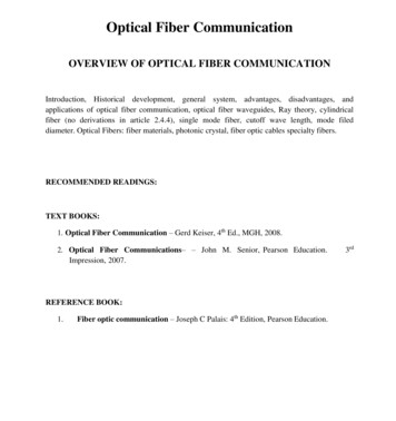
In short, we will review our recent work in three critical aspects of the optical fibers for sensing in harsh environments:waveguide optimization and design for sensing, coating thermal stability, and mechanical strength and fatigue of opticalfibers at elevated temperatures.2. FIBER DESIGN FOR SENSING2.1 Graded-Index multimode fiber (GIMM) with bandwidth optimized for DTS at 1550 nmRaman-based distributed temperature sensing (RDTS) has become an essential tool in oil & gas production, pipelinemonitoring, fire detection, heat tracing, industrial process monitoring, transportation monitoring, and monitoring ofpower transmission lines, etc. [6]. The RDTS systems are capable of achieving high temperature measurement accuracyof 0.1 C, spatial resolution of less than 0.5 m, and distributed measurements over ranges exceeding 30 km [6, 7].GIMM 50/125 optical fibers are the de facto choice for RDTS. However, commercially available GIMM optical fibersare designed for data communications at wavelengths of 850 nm and 1300 nm with highest bandwidth associated withsuch wavelengths commonly used for data transmission. For example, the bandwidth of an OM4 fiber at 850nm canreach several GHz·km. However because of the material dispersion, the value becomes much lower at wavelengths faraway from the designed wavelength. Often, sensing systems operate at wavelengths other than 850 or 1300 nm. Assuch, accuracy and spatial resolution may suffer unless the waveguide is optimized for best use at the operatingwavelength of the sensing system itself.Some RDTS systems are designed to operate at 1550 nm to take advantage of the much lower fiber attenuation in thiswavelength region. Doing so achieves better temperature accuracy and takes advantage of lower cost componentscommercially available at 1550 nm. However, if standard GIMM optical fibers are used for RDTS at 1550 nm, theintermodal dispersion will cause significant pulse broadening, limiting spatial resolution to a few meters. For manyapplications, this may not be acceptable.Our solution is to design a GIMM fiber with the optimized bandwidth at 1550 nm. The refractive index profile ismodified to minimize intermodal pulse broadening at 1550 nm based on theoretical predictions. For a GI MM fiber withcylindrical symmetry, the refractive index n(r) of the core can be described by the equation below:Where r is the distance from the center of the core; is the core radius;, and is the profile exponent.of the core and atandare the refractive indices at the centerThe intermodal pulse broadening of the GIMM fiber with such index distribution has been studied since the 1970’s, andthe bandwidth of a GI MM fiber can be theoretically predicted [8, 9]. The bandwidth, which is inversely proportional topulse broadening, depends on the α value, wavelength, material dispersion and index difference ( ) of the fiber.However, minimum pulse broadening can be achieved at each wavelength with an optimum α value. For example, for aGIMM fiber with a numerical aperture (NA) of 0.2, the optimum α is 2.027 at 850 nm and 1.871 at 1550 nm. Thecalculated root mean square (RMS) pulse width with α 2.027 and 1.871 vs. wavelength is plotted in Figure 1 to showthe dependence of the pulse broadening on and wavelength. It is evident that if we use a GI MM fiber optimized for850 nm at 1550 nm, the pulse broadening is an order of magnitude greater than that of a fiber optimized for minimalpulse broadening at 1550 nm.
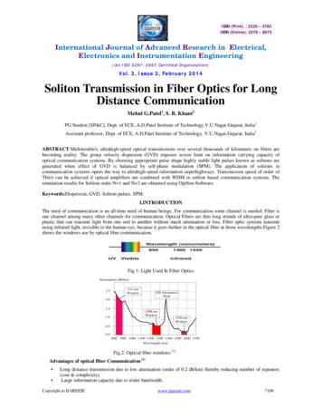
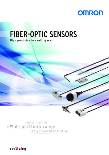
Figure 1. The calculated RMS pulse broadening with α 2.027 and 1.871The idea was experimentally demonstrated by producing and testing a fiber with an index profile having equal to1.871. The resultant bandwidth at three wavelengths is plotted below in Figure 2.Figure 2. The measured bandwidth at 850 nm, 1310 nm and 1550 nmThe median of the measured bandwidth at 1550 nm is 4255 MHz·km while it is 560 MHz·km at 850 nm. The minimumbandwidth is 1800 MHz·km at 1550 nm, which is significantly higher than few hundred MHz·km for an OM4 MM fiber.To test the fiber performance in an RDTS, the pulse broadening at 1550nm with 32 km of the GIMM fiber was measuredand compared with 32 km of conventional OM4 fiber. The input pulse, with a 10 ns pulse width, and the output pulsesafter the 32 km of both fibers are plotted in Figure 3. Pulse broadening is confirmed to be less than 2 ns for the new GIfiber while performance-limiting pulse broadening is 40 ns for the conventional OM4 fiber.Figure 3. Comparison of measured output pulse shape from the new fiber and a standard OM4 fiber
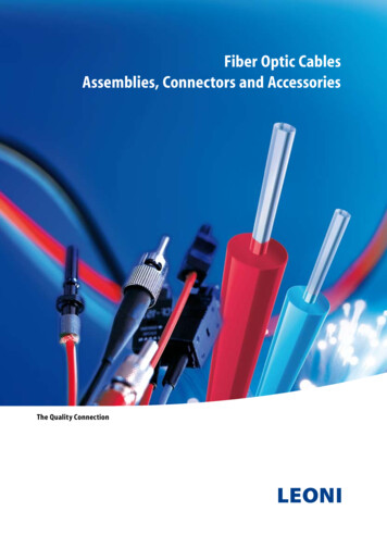
Figure 4. Test setup for RDTS measurement to determine spatial resolution.The improvement of spatial resolution is then demonstrated in an RDTS measurement. The anti-Stokes signals with32km of OM4 fiber or the bandwidth optimized GI fiber were acquired in a test setup shown in Figure 4 where a sectionof 100 m of fiber was heated to 50 in a thermal chamber and the temperature distributions were calculated. Thecalculated temperatures vs. distance near the input of the 100 m fiber kept in the chamber are shown in Figure 5. Thefiber temperature is transitioning from room temperature, right outside the thermal chamber, to 50 C, inside thechamber, and the spatial resolution can be readily calculated for this transition. The spatial resolution is defined as themeasured spatial distance between the 10% and 90% levels of the response to a step temperature change. Based on thetemperature traces shown in Figure 5, the spatial resolution is 3 m at 32 km for the 1550 nm bandwidth optimizedGIMM fiber while it is 10 m at 32 km for the OM4 fiber. The spatial resolution is improved by more than a factor of 3and this is realized simply because the increased bandwidth at 1550 nm enables small pulse broadening after 32 km offiber.Figure 5. The experimental DTS measurements near the input of the 100 m length of fiber in the thermal oven.In summary, we have designed and manufactured a new GIMM optical fiber that enables minimum intermodal pulsebroadening at 1550 nm. Using the fiber at 1550 nm, we have demonstrated a spatial resolution of less than 3 m after 32km of the fiber in RDTS measurements, an enhancement of a factor of 3 as compared with the resolution achievable witha conventional OM4 fiber.2.2 Dual multi-mode core fiber and sensor for DTSRDTS uses the principles of Optical Time Domain Reflectometry (OTDR) to measure the Raman backscatteringoriginating along the length of the fiber. RDTS then computes the ratio of the intensities of Anti-Stokes and Stocksbackscattered peaks to determine temperature changes in a distributed way [10]. As the Anti-Stokes peak is moretemperature sensitive than the Stokes peak, the measurement of the ratio enables the measurement of the temperature.Since the wavelength difference between the Stokes and Anti-Stokes peaks can be greater than 100 nm, the optical lossesat these two wavelengths, wavelength dependent loss (WDL), could be problematic over a long length of fiber. Thisoften leads to significant error in temperature measurement. WDL can be caused by Rayleigh scattering linearly
distributed within the fiber, limited number of fiber splices and connectors, unpredictable stresses along the length of thefiber and sometimes hydrogen or radiation induced loss in the optical fiber.Several methods have been used for WDL associated error in DTS, such as the two light source approach [11], a methodthat uses a high reflection mirror at the far end of the fiber [12], and dual-ended systems [13]. Among all of thesemethods, the dual-ended systems are more attractive as they can automatically correct errors caused by WDL, althoughthe light path length required is two times that of the single-ended method. Dual-ended systems often lead to morecomplicated installation process, especially when the two independent fibers may need to be installed separately andfield-connected at the distal end in order to create the dual-ended light pathway.In a typical dual-ended system, two individual optical fibers are laid parallel to each other and are connected at the distalend so that light can be launched into each leg at the proximal end. The connection at the distal end is typically made bybending a short length of fiber and splicing the short fiber with the two lengths of sensing fiber together, forming a Ushaped optical path. The short U-shaped section of the fiber is then packaged and sealed inside a glass capsule.However, there are several disadvantages associated with this design. Aside from the optical loss induced by the tightbend, mechanical stresses caused by the bend could limit the lifetime of the device. Furthermore, bulky size of theglass protective capsule around this “bend” may interfere with packaging and installation of the finished sensor,especially in applications with confined spaces,We have taken the approach of optimizing design of the fiber and fiber-based components for RDTS sensingapplications. Rather than making a sensor using existing fiber, we have designed a single fiber sensor for dual endedsystem using 1) a dual-core fiber with 2) a miniaturized, matched diameter, solid-state turn-around device, known as amicro-turnaround, built with a graded index (GRIN) MM fiber and 3) a fan-out device and demonstrated the sensor indual-ended RDTS.The dual-core fiber consists of two 50 µm multimode cores, identical to the cores for the 50/125 GIMM fiberscommonly used for DTS, spaced 100 µm apart, as shown in Figure 6. Its outer glass cladding diameter is 200 µm,allowing greater separation between the cores to minimize the crosstalk. The large spacing between the cores alsosimplifies its connection to two individual single-core GI MM fibers in a fan-out device. The fiber is coated with dualacrylate coating to a 350 µm diameter.Figure 6. End-face image of the dual-core fiber taken by an optical microscope with the fiber illuminated from both endsLow optical crosstalk between the two cores is important for the dual-core fiber as high crosstalk could create errors inthe temperature measurement. Crosstalk is related to factors such as spacing between the cores, core diameter variation,scattering and fiber bending. We used fiber bending to induce worst case crosstalk utilizing a 2-point bend device. Along dual-core fiber, 2.63 km in length, was coiled onto a 10-inch spool with fan-out devices spliced to both ends of thefiber. 1064nm light was launched into one core at the input end and the power from both cores was measured at theoutput end. The crosstalk is defined as crosstalk 10 log( P 2 / P1) where P1 is the measured power exiting from thecore in which the light was launched, and P2 is from the other core, or second half of the light’s pathway. A section ofthe dual-core fiber near the output end was put into a 2-point bend device to bend the fiber at 180 degrees for worst casecrosstalk inducement. The cross talk result is shown in Figure 7.
Figure 7. Crosstalk vs. bend diameter at 1064nm.The micro-turnaround device used here measures less than 300 µm in diameter and less than 2 mm in length. The distalend of a dual-core based fiber sensor with a micro-turnaround (darker section) is shown together with a conventionalfiber bend device with two fibers in Figure 8.Figure 8. Images of the micro-turnaround (Top) and the fiber bend device (Bottom).As illustrated in Figure 9, the left side represents the dual-core fiber while the right side represents a GRIN fiber lenswith a high reflectance coating applied to its end face. The cladding diameter of the GRIN fiber lens in our experiment is200 µm to match that of the dual-core fiber, as shown in the top half of the photograph in Figure 2.Figure 9. Illustration of dual-core fiber turnaround.The index distribution of the GI fiber lens can be described as [14]:n(r ) n0 (1 g2 2r )2(2)where r is radial distance from the center, n is refractive index at the center of the GRIN fiber, and g is the gradient. Thegradient g is related to the measured NA and the core size a by:0g NAa n0(3)A beam propagating in the GI medium follows a sinusoidal path, and the pitch or period of the sinusoidal path [14] is:P 2π / g(4)
With a high reflection mirror placed at the ¼ pitch position, the input from one core will be mirrored to its opposing side(opposite core) with a 1:1 ratio in dimension. We illustrate this in Figure 4 with the traces calculated using a ray tracingmethod. The light exiting from Core 1 will expand and become collimated by the GRIN fiber lens, be reflected by themirror and then be focused back onto Core 2, completing the desired turnaround path. The core diameter of the GRINfiber lens is 180 µm and the NA is 0.275 with the calculated ¼ pitch length 757 µm based on equation (3).To connect between the dual-core structure and two individual single-core multimode fibers, fan-out devices weredesigned and made with commercially available GI 50/125 fibers and the dual-core sensor fiber. The fan out has aninsertion loss of 0.5dB from 850nm to 1300 nm, and a crosstalk -60dB. The dual-core end of the fan-out can bespliced to the dual-core fiber using commercially available fusion splicers designed for polarization maintaining (PM)fiber splicing, and the splicing loss of the two cores is typically 0.1dB.After optically characterizing the sensor, the dual-core fiber is tested in an RDTS experiment. The experimental set up isshown in Figure 1, where a section of the fiber sensor is placed in a thermal chamber heated to various temperatures withlead-in and tail sections of the sensor placed outside of the thermal chamber.Figure 10. Setup for distributed temperature measurement with dual-core optical fiberThe sensor fiber used for the thermal test had two 50 µm GI cores with 100 µm separation and a glass cladding diameterof 225 µm. This fiber was further coated with a polyimide coating (high temperature) to a diameter of 260 µm in orderto work at elevated temperature up to 300 C. A fan-out was spliced to the dual-core fiber to couple light in and out ofthe two individual cores. The output fiber from the Raman OTDR could be spliced to either of the two 50/125 GI fibersto interrogate the dual-core fiber in either forward or backward direction. A micro-turnaround device [17] was spliced tothe end of the dual-core fiber to form a complete turnaround loop.The total length of the dual-core fiber was 2620 meters (m). A 50 m section from the middle of the fiber was put in athermal chamber and the rest of the sample were kept at room temperature (around 16 C) as reference as shown inFigure 10.During the test, the temperatures was set to, -25 C, 50 C, 100 C, 200 C and 300 C respectively, and the Stokes andAnti-Stokes signals were obtained from either end of the fan-out alternatingly. The ratios of the Anti-Stokes to Stokesintensities were then calculated to determine the temperature distribution of the fiber. The measured temperaturedistributions are shown in Figure 11 (a) with an enlarged view for the 50 m section shown in Figure 11 (b).
(a)(b)Figure 11. (a) the measured temperature profile of the dual-core fiber with a micro turn-around device; (b) measured temperaturearound the 50 m section in thermal oven and the Stokes signal with the fiber at the room temperature.We have designed a dual core fiber based DTS sensor with miniaturized turnaround, and a fan-out device and havedemonstrated its advantages in a distributed RDTS measurement. This single fiber, dual-core design with a microturnaround is self-calibrating, significantly simplifies the engineering effort required for installation and improves thereliability of the sensor.3. THERMAL STABILITY OF FIBER COATINGSLogically, for optical fibers used in DFOS, coating systems will also need to ensure proper level of coupling of thechanges in physical variables from the environment to the fibers as the sensing media, such as strain coupled from theenvironment to the fiber core in a strain sensing fiber. However, we concentrate our work here on the basic role of thecoatings, that is, to provide mechanical protection to the fiber, especially in harsh environments.There are several factors that define the harshness of the environments for the fiber coatings in DFOS: (1) Physicalenvironment that the fiber coatings are in direct contact with, such as, inside a stainless steel tube or a conduit, in acomposite material, and other packaging configurations); (2) Chemical environments, such as in water, oil, vapor, acids,bases, and hydrogen containing gas or liquid; (3) exposure temperature and (4) exposure pressure. In this work, wefocus on the impact of elevated temperatures on the fiber, as it is the most common and challenging variable encounteredin harsh environments.Thermal stability of the coatings that are protecting the fibers dictate the thermal stability of silica optical fibers withthese coatings since silica glass is more thermally stable than polymer coatings used for optical fibers. All polymercoatings start to experience a gradual process of thermal decomposition when the environment provides a sufficientlyhigh amount of thermal energy. As the molecules of the polymers are being gradually released into the atmospherethrough thermal decomposition, the coating experiences the irreversible process of weight loss, manifested by thediameter reduction of fiber coating itself, change in coating modulus and coating deformation. The changes in thecoating lead to weakening and eventual mechanical breakage of the coated fiber. Therefore the challenge for reliable useof fibers is to develop a coating that protects the fiber at the desired temperature for the intended duration.3.1 TGA and thermal stabilityIf the thermal weight loss of polymer materials is considered the main failure mechanism, the thermal stability ortemperature rating of the fibers protected with these coatings should be defined by both temperature and duration. Toquantitatively evaluate the thermal stability of the fibers coated with different coatings, we proposed an approach thatties fiber failure with coating property changes [5, 16]. In this method, thermogravimetric analysis (TGA) of coatedfiber samples is coupled with a test of the coated fiber for a specific failure mode at corresponding temperatures. Morespecifically, first, an interested failure mode and its criterion are selected. For example, the failure mode could beinduced-optical attenuation, loss of mechanical strength, cracking or discoloration of the coating, and loss of volatilecompounds, etc. Once the failure mode and its criterion are defined, the fiber is aged at a preset elevated temperatureuntil this failure is observed as in the middle section of Figure 12 to determine its lifetime at elevated temperatures. A
TGA experiment is performed for the same temperature range to determine the corresponding weight loss of the coatingat the time of the fiber failure as indicated by the lower section in Figure 12. In this way, the failure mode of an opticalfiber is linked with a TGA weight loss, which can be treated as the failure TGA weight loss for the specific fiber failuremode.Figure 12. Explanation of the TGA approach.The TGA data collected isothermally at different temperatures or non-isothermally at different heating rates can be usedfor evaluating the times and temperatures that correspond to the failure weight loss and then extrapolated to lower orhigher temperature regions with longer or short lifetimes. Another use of the method is to compare the thermal stabilityfor different coatings. For instance, we may select an arbitrary failure criterion of 25% of the coating weight loss for anarbitrary failure mode. Examples of the results obtained for fibers coated with dual acrylate, silicone and polyimidecoatings are shown in Figure 13. Extrapolation of the data to 20-year lifetimes yields the following upper usetemperatures: 90 C for the dual acrylate coating, 125 C for single acrylate; 160 C for silicones and 245 C fortraditional polyimides.Figure 13. Continuous usage time plotted vs. temperature for fibers with dual acrylate, silicone and polyimide coatings in airenvironment. The data are based on TGA analysis assuming 25% weight loss criterion.3.2 Pyrocoat KBuilding on this foundation, we recently developed a polyimide coating with enhanced thermal stability, Pyrocoat K.For this coating, the upper use temperature with 20 year lifetime is 293 C [17], enabling a possible solution to a veryspecific issue for the polyimide coating at elevated temperatures. Above 250 C, typical polyimides approach their glasstransition temperature and become “sticky”. In practice, such polyimide-coated fibers adhere to most surfaces theycontact, such as the inner wall of a Fiber-In-Metal-Tube (FIMT), commonly used for fiber packaging in oil and gas
sensing. Subsequent cooling of the FIMT may lead to mechanical breakage of the fiber due to a breach in coating and ora CTE mismatch between the metal and silica glass.To evaluate the issue of stickiness of polyimide-coated fibers to metal, the following experiment was performed. Piecesof polyimide-coated fiber were bent into a U-shape and inserted into ¾’’ ID stainless steel tubes. The specimens werethen places in a thermal oven and kept at 300 C for 24 hours. After cooling to room temperature, it was observed thatthe fibers adhered to the inner wall of the stainless tube and could not be removed from the tubes without breaking theoptical fibers. Figure 14 shows a piece of stainless steel tube hanging onto the fiber that is stuck onto its inner wall.Similar experiments were performed using fibers coated with the Pyrocoat K polyimide. This coating was designed tobe less sticky to metal surfaces and Pyrocoat K coated fibers exhibited no adhesion to the stainless steel tube withidentical 300 C exposure.This experimentation has practical implications as it solves a significant reliability problem for those using optical fiberswithin m
Since its inception more than 30 years ago, Distributed Fiber Optic Sensing (DFOS) has been widely recognized and gradually adopted as a critical sensing technology in many applications such as oil and gas pipeline leak sensing, detection, perimeter security and structural health monitoring [1,2]. Optical fibers optimized for DFOS harsh in