Transcription
FORD 4R100"UPDATE HANDBOOK"INDEX3PRELIMINARY DIAGNOSTIC INFORMATION .6IDENTIFICATION TAG LOCATION AND INFORMATION .9LUBE ORIFICE PLUG AND EXTENSION HOUSING INFORMATION .11MANUAL LEVER IDENTIFICATION .12COOLER BYPASS VALVE DIFFERENCES .14PUMP COVER VALVES EXPLODED VIEW .15PUMP STATOR DIFFERENCES .16COAST CLUTCH HOUSING DIFFERENCES .18OVERDRIVE ROLLER CLUTCH DIFFERENCES .19OVERDRIVE FRICTION DIFFERENCES .20VALVE BODY CHECKBALL LOCATIONS .21LOWER VALVE BODY SPACER PLATE IDENTIFICATION .22MAIN CASE CHECKBALL LOCATIONS .23ALL VALVE BODIES EXPLODED VIEWS .25ELECTRONIC COMPONENT RESISTANCE CHARTS .27SOLENOID CONNECTOR PIN IDENTIFICATION .29TROUBLE CODE CHART AND DESCRIPTION .34POWER TAKE OFF DESCRIPTION AND OPERATION .38"NON-PTO" AND "PTO" HYDRAULIC DIFFERENCES .39MAIN CASE CENTRAL LUBE ADDED .40SPACER PLATE DIFFERENCES PTO AND NON-PTO .50"NON-PTO" AND "PTO" PUMP DIFFERENCES .56PWM SOLENOID PACK RESISTANCE CHART .57SIX PINION FORWARD AND REAR PLANETARY CARRIERS .60NEW DESIGN SUN SHELL .64INTERMEDIATE DIODE FREEWHEEL FAILURE .67HYDRAULIC PASSAGE IDENTIFICATION .77NO TCC AT LESS THAN 30% THROTTLE .NEW "SPECIAL" 4R100 CASE FOR E4OD REPLACEMENT . 8297ARTICLE ON PTO OPERATION.PTO OIL CIRCUIT DIAGRAMS. 100AUTOMATIC TRANSMISSION SERVICE GROUP18639 S.W. 107 AVENUEMIAMI, FLORIDA 33157(305) 670-4161Copyright ATSG 2005
INTRODUCTIONOriginal PrintingFebruary, 2005FORD 4R100"UPDATE HANDBOOK"Since the introduction of the 4R100 transmission in model year 1998, there have been many engineeringchanges to improve Pleaseability, Reliability and Durability concerns. These changes have affected most everypart used in this transmission. This "Update Handbook" will explain each change, the reason for the change,and any parts interchangeability concerns created by the change, along with any part numbers needed to updateyour transmission.We wish to thank Ford Motor Companyfor the information and some illustrationsthat have made this booklet possible.No part of any ATSG publication may be reproduced, stored in any retrieval system or transmitted in any form orby any means, including but not limited to electronic, mechanical, photocopying, recording or otherwise,without written permission of Automatic Transmission Service Group. This includes all text illustrations,tables and charts.The information and part numbers contained in this booklet havebeen carefully compiled from industry sources known for theirreliability, but ATSG does not guarantee its accuracy.Copyright ATSG 2005DALE ENGLANDJIM DIALFIELD SERVICE CONSULTANTTECHNICAL CONSULTANTWAYNE COLONNAED KRUSETECHNICAL SUPERVISORTECHNICAL CONSULTANTPETER LUBANGREGORY LIPNICKTECHNICAL CONSULTANTTECHNICAL CONSULTANTJON GLATSTEINDAVID CHALKERTECHNICAL CONSULTANTTECHNICAL CONSULTANTJERRY GOTTROLAND ALVAREZTECHNICAL CONSULTANTTECHNICAL CONSULTANTGERALD CAMPBELLMIKE SOUZATECHNICAL CONSULTANTTECHNICAL CONSULTANTAUTOMATIC TRANSMISSION SERVICE GROUP9200 S. DADELAND BLVD. SUITE 720MIAMI, FLORIDA 33156(305) 670-41611
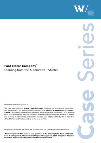
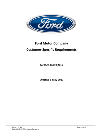
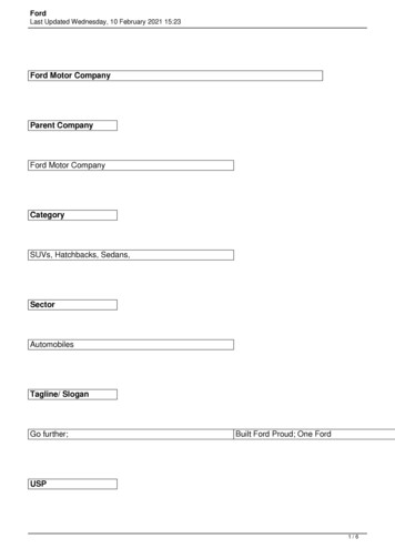
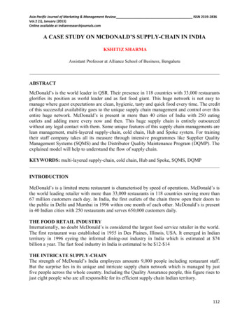
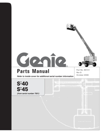
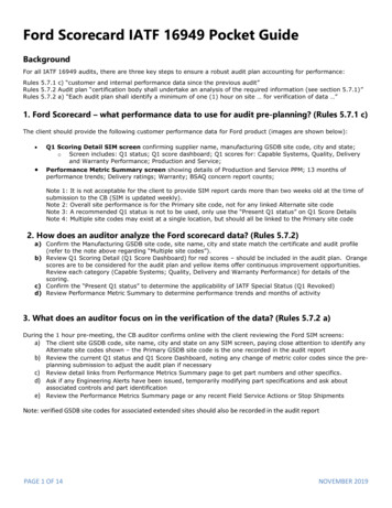
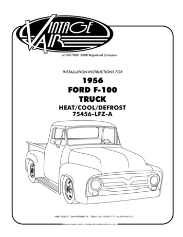
Technical Service InformationFORD 4R100PRELIMINARY INFORMATIONCHANGE: Beginning at the start of production for 1999 models, Ford Motor Company introduced a newtransmission in some F250, F350, F450 and F550 Super Duty Trucks, equipped with the 5.4L,6.8L and 7.3L engines. Basically the new 4R100 is a revised version of the previous E4ODtransmission with a Power-Take-Off (PTO) window on the side of the case (See Figure 1). Therevisions that have occured however, have created many major engineering changes that haveaffected many internal and external parts that will affect service.REASON: Provided a PTO option for Ford Motor Company.PARTS AFFECTED:(1) TRANSMISSION CASE - Now has a PTO window added to the left side of the case directlybehind the front pump area, and a Turbine Speed Sensor has been added at the top of the case andtriggered by a revised coast clutch drum (See Figure 2). Another change to the rear of the case isthe addition of a Lube Orifice Plug to the Rear of the case, as shown in Figure 4, which alsochanges the extension housings.(2) TURBINE SPEED SENSOR - Added to the top front of the case on some models, as shown inFigure 2. We have also provided you with the resistance readings and OEM part numbers on bothTurbine Speed Sensors, as the PTO and Non-PTO models use different sensors. Refer to Figure 2for turbine speed sensor information.(3) OUTPUT SHAFT SENSOR - Output Shaft Speed sensor was added to the top of the extensionhousing on some models, as shown in Figure 2. OSS is triggered by an added rotor pressed onto theoutput shaft, which requires a new tool to position the speed rotor properly if it is removed duringoverhaul, as shown in Figure 3. The park gear is also now pressed onto the output shaft, and thenumber 13 thrust washer has been changed to a thrust bearing as shown in Figure 3. We haveprovided you with the resistance reading and the OEM part numberfor the output shaft speedsensor. Refer to Figure 2 for output shaft speed sensor information.(4) LUBE ORIFICE PLUG - Added to the rear of the case in the lube circuit to provide addedlubrication to the extension housing bushing on 2WD models. To retain common cases the 4WDmodels will also have the lube orifice plug installed, as well as E4OD cases produced after July 24,1997. Lube Orifice Plug is available under OEM part number F81Z-7E380-AA, and should bereplaced on rebuild. Refer to Figure 4.(5) EXTENSION HOUSING - Has an added boss or shoulder to retain the lube orifice plug in positionin the transmission case, as shown in Figure 5. Notice that the 6.8L and 7.3L, 2 wheel driveextension housing has added a new passage to the extension housing bushing, much like the 4L80E. All 4R100 and E4OD transmissions equipped with the lube orifice plug must use an extensionhousing with the shoulder or boss. Failure to do so could blow the lube orifice plug out andexhaust all lube oil, which would be catastrophic. Refer to Figure 5.Continued on next Page.AUTOMATIC TRANSMISSION SERVICE GROUPCopyright 2005 ATSG3
Technical Service InformationPARTS AFFECTED: (Continued)(6) MANUAL SHIFT LEVER - There are two different external shift levers for this unit, one for NonPTO transmissions and one for transmissions with the PTO option, as shown in Figure 6. We haveprovided you with the "Stamping" number as well as the OEM part number for both, as shown inFigure 6.(7) COOLER BYPASS VALVE - Similar to the Cooler Bypass Valve on the E4OD that provideslubrication to the transmission in case of blocked or partially blocked coolers. We have given youOEM part numbers for both and both bypass valves are illustrated in Figure 7.(8) TRANSMISSION COOLERS - Most F-Series vehicles over 8500 GVW equipped with the 4R100transmission have an external "Oil-To-Air" cooler only. Due to the internal design of the "Oil-ToAir" cooler, it cannot be adequately flushed to remove contaminants, and requires replacementduring transmission rebuild. The only exception is that F-Series vehicles over 8500 GVWequipped with the 5.4L engine also uses a radiator "In-Tank" cooler in addition to the "Oil-To-Air"cooler. Refer to Figure 8 for transmission cooler information.(9) FRONT PUMP COVER - The pump cover is basically the same as the E4OD, but has a differentvalve line-up in the Converter Clutch Control Valve bore. The gasoline applications all have an"On-Off" lock-up solenoid and the 7.3L diesel applications all have a Pulse Width Modulated(PWM) lock-up solenoid. This changes the Converter Clutch Control Valve line-ups in the pumpcover, as shown in Figure 9.(10) FRONT PUMP STATOR SHAFT - With the addition of the PTO gear on the front of the coastclutch drum, it was necessary to move the coast clutch sealing ring grooves up on the pump statorshaft to accommodate the coast clutch drum moving. There are currently three different PumpStator Shafts used in production and all three are illustrated in Figure 10. One is the current E4ODshaft which is used with the "Cast Iron" coast clutch drum with 5.4L and 6.8L engines without thePTO option. Two is the shaft with the relocated sealing rings and a bushing in the pump tower,which is used with the "Stamped Steel" coast clutch drum with 5.4L and 6.8L engines without thePTO option. Third is the shaft with the relocated sealing rings and a caged needle bearing in thepump tower, which is used with the "Stamped Steel" coast clutch drum with 6.8L and 7.3L engineswith the PTO option. Refer to Figure 10.(11) COAST CLUTCH DRUM AND STEEL PLATES - There is now a revised "Stamped Steel" coastclutch drum introduced with the 4R100 transmission. There are currently three different coastclutch drums used in production and all three are illustrated in Figure 11. One is the current E4ODcoast clutch drum which is "Cast Iron" and uses the current steel plates. Two is the new design"Stamped Steel" coast clutch drum without the PTO gear pressed on it and uses a new design coastclutch steel plate to accommodate the new drum. Third is the new design "Stamped Steel" coastclutch drum with the PTO gear pressed on it and uses the new design coast clutch steel plates toaccommodate the new drum. The new design "Stamped Steel" coast clutch drum now has theoverdrive roller clutch inner cam made on the drum and the overdrive sun gear is pressed into thenew design drum, which changes the assembly process of the overdrive roller clutch. Refer toFigure 11.(12) COAST CLUTCH PISTON - The coast clutch piston in the new design coast clutch drum is now astamped steel, molded rubber seals assembly and is illustrated in Figure 12. The new design pistonassembly requires a new seal protector tool, Rotunda No. 307-387, to install the piston and sealassembly into the new design stamped steel coast clutch drum (See Figure 12).Continued on next Page.4AUTOMATIC TRANSMISSION SERVICE GROUPCopyright 2005 ATSG
Technical Service InformationPARTS AFFECTED: (Continued)(13) OVERDRIVE ROLLER CLUTCH - The overdrive roller clutch inner cam is now made onto thenew design coast clutch drum, instead of being splined like the previous models were, and isillustrated in Figure 13. The new design overdrive roller clutch assembly is now assembled ontothe inner cam on the new design drum. The overdrive roller clutch outer race is still located in theoverdrive ring gear next to the overdrive carrier and the number 13 thrust washer between the twois now plastic, but the cage and roller assembly are now assembled over the inner race on the newdesign coast clutch drum. Refer to Figure 13.(14) OVERDRIVE FRICTION PLATES - Now have wider teeth to accommodate the new designstamped steel coast clutch drum assembly when it is used, as illustrated in Figure 14.(15) VALVE BODY CHECKBALL LOCATIONS - Valve body checkball locations are illustrated inFigure 15 and now has two 1/4" checkballs and two 5/16" checkballs. This of course changes thelower valve body spacer plate as illustrated in Figure 16. The new design spacer plate has only onehole over the bathtub where the checkball was removed. The case checkball locations remain thesame as the 1996-Up configuration, and this illustration is included for reference and shown inFigure 17.(16) VALVE LINE-UPS IN VALVE BODY - Have changed from the previous models and areillustrated in Figure 18, with a valve description and legend shown in Figure 19.(17) SOLENOID BODY - There are now two different Solenoid Bodies, depending on whether youhave a gasoline or diesel model. Since the diesel models now have a Pulse Width Modulated(PWM) converter clutch application, the resistance on the converter clutch solenoid in theSolenoid Body is going to be different. We have included the OEM part numbers for both solenoidbodies and resistance charts for all solenoids in Figure 20, and you will find solenoid applicationand pin function charts in Figures 21 and 22.(18) TROUBLE CODES - Abbreviations are listed in Figure 23 and OBD II Trouble Codes are listedin numerical order in Figures 24 through 28.INTERCHANGEABILITY:All of the parts listed above are model sensitive, and some of the parts listed above cannot beintermixed with E4OD parts. With this unit you will have to be very carefull if replacement of thevarious components becomes necessary.SERVICE INFORMATION:Turbine Shaft Speed Sensor (PTO Models Only) .Turbine Shaft Speed Sensor (Non-PTO Models Only) .Output Shaft Speed Sensor (All Models) .Lube Orifice Plug (Plastic) .External Manual Shift Lever (With PTO Option) .External Manual Shift Lever (Without PTO Option) .Cooler Bypass Valve Assembly .Coast Clutch Piston (New Design) .Solenoid Body Assembly (Gasoline Engine Only) .Solenoid Body Assembly (Diesel Engine Only) .Overdrive Roller Clutch And Cage Assembly ght 2005 ATSGAUTOMATIC TRANSMISSION SERVICE GROUP5
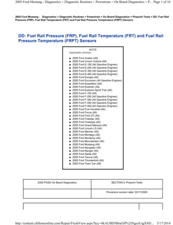
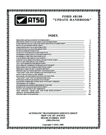
Technical Service InformationFORD 4R100WITH POWER TAKE OFF OPTIONNote: PTO is available as an option on 8500 GVW or above, Super DutyF-Series trucks with 6.8L gasoline and 7.3L Diesel engines.Ford 4R100 transmissions on other models are not PTO P98dForYearBD-65201234004361123499 19990 20001 20012 20023 yC17A JanB FebC MarD AprE MayF JunG JulH AugJ SepK OctL NovM DecAssembly Part Number, Prefix And SuffixTransmission ModelSerial NumberBuild Date (Year, Month, Day)Copyright 2005 ATSGFigure 16AUTOMATIC TRANSMISSION SERVICE GROUP
Technical Service InformationTurbine Shaft Speed SensorOutput Shaft Speed SensorPTO Models Only 496-1244 Ohms ResistancePart Number F81Z-7M101-BAAll Models 781-1979 Ohms ResistancePart Number F81Z-7M101-AANon PTO Models Only 781-1979 Ohms ResistancePart Number 00014474X450CLRALFordF7TP-7F293-AANEUTCopyright 2005 ATSGFigure 2AUTOMATIC TRANSMISSION SERVICE GROUP7
Technical Service InformationFORD 4R100OUTPUT SHAFT SPEED SENSOR ROTOROutput Shaft Speed Sensor Rotor is press fit to the output shaft and requires new Spacer Tool,Rotunda No. 307-388 for spacing the speed sensor rotor the proper distance from the park gear, if itwas removed from the output shaft during service.PARK GEARThe Park Gear is also press fit to the output shaft, and thenumber 13 thrust washer, between the case and the parkgear has been replaced with a needle bearing.SPACER, ROTUNDAPART NUMBER 307-388OUTPUT SHAFTSPEED SENSORROTORPARK GEAROUTPUT SHAFTFigure 38AUTOMATIC TRANSMISSION SERVICE GROUPCopyright 2005 ATSG
Technical Service InformationFORD 4R100LUBE ORIFICE LOCATIONLUBE ORIFICE PLUGFORD PART NUMBERF81Z-7E380-AACopyright 2005 ATSGFigure 4AUTOMATIC TRANSMISSION SERVICE GROUP9
Technical Service InformationEXTENSION HOUSINGS4R100 TYPICAL4 WHEEL DRIVEE4OD 4X4 WITHOUTLUBE PLUGSHOULDERFORD 4R1006.8L AND 7.3L2 WHEEL DRIVENO SHOULDERALL OTHER2 WHEEL DRIVEAPPLICATIONSADDED BOSSE4OD WITHOUTLUBE PLUGSHOULDERNO SHOULDERNOTE: Extension Housings are model sensitive. Refer toFord Motor Co. parts list for proper part numbers.Copyright 2005 ATSGFigure 510AUTOMATIC TRANSMISSION SERVICE GROUP
Technical Service InformationFORD 4R100MANUAL SHIFT LEVERS"With" PTO OPTION"Without" PTO OPTIONSTAMPED F81P-AASTAMPED F75P-BBFORD PART NUMBERF81Z-7A256-AAFORD PART NUMBERF7UZ-7A256-BBCopyright 2005 ATSGFigure 6AUTOMATIC TRANSMISSION SERVICE GROUP11
Technical Service InformationTO COOLERSEALING WASHERS"E4OD" COOLER BYPASSVALVE ASSEMBLYFROM COOLERSEALING WASHERSOEM PART NUMBERF75Z-7H322-ABCOOLER LINEFITTINGS"4R100" COOLER BYPASSVALVE ASSEMBLYTO COOLERSEALING WASHERSFROM COOLERSEALING WASHERSCOOLER LINEFITTINGSOEM PART NUMBERF81Z-7H322-AACopyright 2005 ATSGFigure 712AUTOMATIC TRANSMISSION SERVICE GROUP
Technical Service InformationMost F-Series vehicles over 8500 GVW equipped with the 4R100 transmission have an external "Oil-ToAir" cooler only. Due to the internal design the "Oil-To-Air" cooler cannot be adequately flushed toremove contaminants, and requires replacement during transmission rebuild."OIL TO AIR"COOLERThe only exception is that F-Series vehicles over 8500 GVW equipped with the 5.4L engine also uses aradiator "In-Tank" cooler in addition to the "Oil-To-Air" cooler."OIL TO AIR"COOLERCOOLER LINES FROM TRANSMISSIONTO COOLER IN RADIATORCopyright 2005 ATSGFigure 8AUTOMATIC TRANSMISSION SERVICE GROUP13
Technical Service InformationFORD 4R100VALVE LINE-UPS IN PUMP ASSEMBLY15 Diesel EnginePWM Only.1223141189Gasoline Engine"On-Off" Only.101112341. Pressure Regulator Valve2. Spring Retainer3. Pressure Regulator Outer Spring4. Pressure Regulator Inner Spring5. Pressure Regulator Boost Valve6. Pressure Regulator Boost Valve Sleeve7. Snap Ring8. Converter Clutch Regulator Valve9. Converter Clutch Regulator Spring10. Converter Clutch Regulator Bore Plug11. Bore Plug Retainer12. Converter Clutch Control Valve (Gas "On-Off" Only)13. Converter Clutch Control Spring (Gas "On-Off Only)14. Converter Clutch Control Bore Plug15. Converter Clutch Control Line-up (Diesel "PWM" Only)567Copyright 2005 ATSGFigure 914AUTOMATIC TRANSMISSION SERVICE GROUP
Technical Service InformationBUSHINGCOAST CLUTCHSEAL RINGS ARELOW ON PUMP TOWER(LIKE E4OD)USED WITH THE "CAST IRON" COAST CLUTCH DRUMWITH 5.4L AND 6.8L "WITHOUT" PTO OPTIONBUSHINGCOAST CLUTCHSEAL RINGS ARE HIGHERON THE PUMP TOWERUSED WITH THE "STAMPED STEEL" COAST CLUTCH DRUMWITH 5.4L AND 6.8L "WITHOUT" PTO OPTIONCAGED NEEDLEBEARINGCOAST CLUTCHSEAL RINGS ARE HIGHERON THE PUMP TOWERThe Caged Needle Bearing shownhere, allegedly never made it toproduction, but we have seen someout there.USED WITH THE "STAMPED STEEL" COAST CLUTCH DRUMWITH 6.8L AND 7.3L "WITH" PTO OPTIONCopyright 2005 ATSGFigure 10AUTOMATIC TRANSMISSION SERVICE GROUP15
Technical Service InformationCOAST CLUTCHSTEEL PLATES"CAST IRON" COAST CLUTCH DRUM USEDWITH 5.4L AND 6.8L "WITHOUT" PTO OPTIONCOAST CLUTCHSTEEL PLATES"STAMPED STEEL" COAST CLUTCH DRUM USEDWITH 5.4L AND 6.8L "WITHOUT" PTO OPTIONCOAST CLUTCHSTEEL PLATES"STAMPED STEEL" COAST CLUTCH DRUM USEDWITH 6.8L AND 7.3L "WITH" PTO OPTIONCopyright 2005 ATSGFigure 1116AUTOMATIC TRANSMISSION SERVICE GROUP
Technical Service InformationSTAMPED STEEL MOLDED RUBBER COAST CLUTCH PISTONFOR NEW DESIGN COAST CLUTCH DRUMNEW DESIGN STAMPED STEEL,MOLDED RUBBER SEAL PISTONOEM PART NUMBER F81Z-7A262-AANEW DESIGN STAMPED STEELCOAST CLUTCH DRUMLIP SEAL PROTECTORROTUNDA NO. 307-387NEW DESIGN STAMPED STEELMOLDED RUBBER PISTONCopyright 2005 ATSGFigure 12AUTOMATIC TRANSMISSION SERVICE GROUP17
Technical Service InformationSnap RingNumber 3 ThrustWasher is now Plastic.OverdriveRing GearOverdrive RollerClutch Outer RaceOVERDRIVE ROLLER CLUTCHAND CAGE ASSEMBLYPART NUMBER F81Z-7A089-AAThe rollers and plastic cage are smaller and no longer assembledinto the back of the overdrive ring gear. The outer race remainsin the back of the overdrive ring gear next to the overdrive carrier,but the rollers and cage are now installed over the inner race onthe new design coast clutch drum.New Design "Stamped Steel"Coast Clutch Drum AssemblyCopyright 2005 ATSGFigure 1318AUTOMATIC TRANSMISSION SERVICE GROUP
Technical Service InformationOVERDRIVE CLUTCHFRICTION PLATES"CAST IRON" COAST CLUTCH DRUM USEDWITH 5.4L AND 6.8L "WITHOUT" PTO OPTIONOVERDRIVE CLUTCHFRICTION PLATES"STAMPED STEEL" COAST CLUTCH DRUM USEDWITH 5.4L AND 6.8L "WITHOUT" PTO OPTIONOVERDRIVE CLUTCHFRICTION PLATES"STAMPED STEEL" COAST CLUTCH DRUM USEDWITH 6.8L AND 7.3L "WITH" PTO OPTIONCopyright 2005 ATSGFigure 14AUTOMATIC TRANSMISSION SERVICE GROUP19
Technical Service InformationFORD 4R1004R100 VALVE BODY CHECKBALL LOCATIONSREQUIRES TWO 1/4" RUBBER BALLS,AND TWO 5/16" RUBBER BALLSROUGH FORGINGNUMBER LOCATIONRF-F6TP7A092-ABX5/16" DIAMETERCHECKBALL5/16" DIAMETERCHECKBALL1/4" DIAMETERCHECKBALLSCopyright 2005 ATSGFigure 1520AUTOMATIC TRANSMISSION SERVICE GROUP
Technical Service Information"Two" Holes OverThe Bathtub1996-1999 "E4OD" LOWERVALVE BODY SPACER PLATEIDENTIFICATIONONE "V" NOTCHTHREE "SMALL" HOLES"One" Hole OverThe Bathtub1999 MODEL "4R100" LOWERVALVE BODY SPACER PLATEIDENTIFICATION ONE"DOVETAIL" NOTCHTHREE "SMALL" HOLESCopyright 2005 ATSGFigure 16AUTOMATIC TRANSMISSION SERVICE GROUP21
Technical Service Information1999 4R100 CASE CHECKBALL LOCATIONSREQUIRES EIGHT (5/16") RUBBER ORREGULATOR CB-14FILTER ASSEMBLYSHIFT 1AIR BLEEDCB-9SHIFT 2AIR BLEED1/4" STEEL BALLEPC RELIEF BALLFilter Assembly . F1TZ-7H194-AEPC Spring . E9TZ-7D017-ASPRING GOES INTOTHE CASE FIRSTSPRING GOES INTOTHE CASE FIRST(USED ALL MODELS)Copyright 2005 ATSGFigure 1722AUTOMATIC TRANSMISSION SERVICE GROUP
Technical Service InformationFORD 4R100MAIN, LOWER, AND ACCUMULATOR VALVE BODIES EXPLODED VIEW12548769314151311101212203029281918 1716TP- 156575859Copyright 2005 ATSG60Figure 18AUTOMATIC TRANSMISSION SERVICE GROUP23
Technical Service InformationFORD 4R100MAIN, LOWER, AND ACCUMULATOR VALVE BODY LEGENDItem DescriptionItem Description1Lower Valve Body47Spring Clip Bore Plug Retainer2Hex Head Bolt, M1 X 36 (2 Required)48Direct Clutch Accumulator Regulator Plunger Bore Plug3Retaining Plate49Direct Clutch Accumulator Regulator Plunger Spring4Manual 1-2 Transition Valve Spring50Direct Clutch Accumulator Regulator Plunger5Manual 1-2 Transition Valve51Direct Clutch Accumulator Regulator Valve Retainer6Spring Clip Bore Plug Retainer52Direct Clutch Accumulator Regulator Valve Spring7Engagement Valve Bore Plug53Direct Clutch Accumulator Regulator Valve8Engagement Valve Spring54Spring Clip Bore Plug Retainer9Engagement Valve55O.D. Clutch Accumulator Regulator Plunger Bore Plug10Main Valve Body56O.D. Clutch Accumulator Regulator Plunger Spring11Checkball 1/4", 2 Required (7E195)57O.D. Clutch Accumulator Regulator Plunger12Checkball 5/16", 2 Required (7E195)58O.D. Clutch Accumulator Regulator Valve Retainer13Manual Control Valve59O.D. Clutch Accumulator Regulator Valve Spring14Manual Valve "E" Clip60O.D. Clutch Accumulator Regulator Valve15Spring Clip Bore Plug Retainer61Spring Clip Bore Plug Retainer16Low Reverse Modulator Valve Sleeve62Int. Clutch Accumulator Regulator Plunger Bore Plug17Low Reverse Modulator Valve Plunger63Int. Clutch Accumulator Regulator Plunger Spring18Low Servo Modulator Valve Spring64Int. Clutch Accumulator Regulator Plunger19Low Servo Modulator Valve65Int. Clutch Accumulator Regulator Valve Retainer20Low Reverse Modulator Valve66Int. Clutch Accumulator Regulator Valve Spring21Spring Clip Bore Plug Retainer67Int. Clutch Accumulator Regulator Valve223-4 Shift Valve Bore Plug68Spring Clip Bore Plug Retainer233-4 Shift Valve Spring69Line Pressure Modulator Plunger Sleeve243-4 Shift Valve70Line Pressure Modulator Plunger25Retaining Plate71Line Pressure Modulator Spring And Retainer Assembly262-3 Shift Valve Spring72Line Pressure Modulator Valve Spring272-3 Shift Valve73Line Pressure Modulator Valve28Retaining Plate29Solenoid Regulator Valve Spring30Solenoid Regulator Valve31Retaining Plate32Coast Clutch Shift Valve Spring33Coast Clutch Shift Valve34Retaining Plate354-3-2 Shift Timing Control Valve Plunger Spring364-3-2 Shift Timing Control Valve Plunger37Retaining Plate384-3-2 Shift Timing Valve394-3-2 Shift Timing Valve Spring40Spring Clip Bore Plug Retainer411-2 Shift Valve Bore Plug421-2 Shift Valve43Drive 2 Valve441-2 Shift Valve Spring46Accumulator Valve Body (7G422 Model Sensitive)Copyright 2005 ATSGFigure 1924AUTOMATIC TRANSMISSION SERVICE GROUP
Technical Service InformationFORD 4R100SOLENOID RESISTANCE CHARTSSolenoid Resistance ChartSolenoid BodySolenoidPin NumbersShift Solenoid "B" (2)Shift Solenoid "A" (1)TCC Solenoid, Gasoline (On-Off)TCC Solenoid, Diesel (PWM)Coast Clutch SolenoidElectronic Pressure Control SolenoidTransmission Fluid Temp Sensor1 and 21 and 31 and 41 and 41 and 511 and 127 and 8Resistance20-30 Ohms20-30 Ohms20-30 Ohms10-20 Ohms20-30 Ohms3.0-5.0 OhmsSee Chart BelowTransmission Fluid Temperature C FResistance-40 to -20-19 to -10 - 2021-4041-7071-9091-110111-130131-150-40 to -4-3 to 62k - 284k W284k - 100k W100k - 37k W37k - 16k W16k - 5k W5k - 2.7k W2.7k - 1.5k W1.5k - 0.8k W0.8k - 0.54k WSOLENOID ASSEMBLYGasoline Engines Only - Part Number F81Z-7G391-BADiesel Engines Only ----- Part Number F81Z-7G391-ABCopyright 2005 ATSGFigure 20AUTOMATIC TRANSMISSION SERVICE GROUP25
Technical Service InformationShift Solenoid Application ChartSelector Lever CommandedRangeGearP/R/NDDDDDCancelMANUAL 2MANUAL 1MANUAL 1*11234ShiftSolenoid "A"ShiftSolenoid "B"TCCSolenoidCoast irst Through 3rd Gear Only, SSA, SSB, TCC, Same as Overdrive, CCS Always On.221***OFFONOFFOFFOFFOFFONONONControlled by PCMSHIFT SOLENOID "A" ALWAYS OFFSelector Lever PositionD21PCM GearCommandedActual Gear Obtained1st4212nd3223rd3224th422SHIFT SOLENOID "B" ALWAYS OFFSelector Lever PositionD21PCM GearCommandedActual Gear Obtained1st1212nd1213rd4224th422SHIFT SOLENOID "A" ALWAYS ONSelector Lever PositionD21PCM GearCommandedActual Gear Obtained1st1212nd2213rd2214th121SHIFT SOLENOID "B" ALWAYS ONSelector Lever PositionD21PCM GearCommandedActual Gear Obtained1st2212nd2213rd3224th322Copyright 2005 ATSGFigure 2126AUTOMATIC TRANSMISSION SERVICE GROUP
Technical Service InformationFORD 4R100SOLENOID BODY PIN IDENTIFICATION AND FUNCTIONSOLENOID BODYCONNECTORVEHICLE HARNESSCONNECTOR7 81211 126 5 4321716SOLENOID ASSEMBLYGasoline Engines Only - Part Number F81Z-7G391-BADiesel Engines Only ----- Part Number F81Z-7G391-ABCopyright 2004 ATSGSolenoid Connector Pin Identification and FunctionPin No.123456789101112DescriptionVehicle Power In For Solenoids (VPWR)Shift Solenoid "B" (2) Ground from PCMShift Solenoid "A" (1) Ground from PCMConverter Clutch Solenoid Ground from PCMCoast Clutch Solenoid Ground from PCMNot UsedTransmission Fluid Temp SensorTransmission Fluid Temp Sensor (Signal Return)Not UsedNot UsedElectronic Pressure Control (EPC)Vehicle Power In For EPC Solenoid (VPWR)PCM Connector PinGas & Diesel (Cal) Diesel (49 State)71, 9771, 9711162754282053379137918171, 978171, 97Figure 22AUTOMATIC TRANSMISSION SERVICE GROUP27
Technical Service Information1999 FORD 4R100Abbreviation BOOBPABPPCCSCPPCRUISEDLCDTCDTC CNTDTREBPDescription4X4 Low SwitchAntilock Brake SystemAir ConditioningAir Conditioning Clutch StatusAccelerator Pedal Position SensorAncillary Engine Speed DesiredBarometric Pressure SensorBrake ON/OFF SwitchBrake Pressure Applied
"UPDATE HANDBOOK" AUTOMATIC TRANSMISSION SERVICE GROUP 9200 S. DADELAND BLVD. SUITE 720 MIAMI, FLORIDA 33156 . Ford Motor Company introduced a new transmission in some F250, F350, F450 and F550 Super Duty Trucks, equipped with the 5.4L, . COOLER BYPASS VALVE - Similar to the Cooler By