Transcription
USER'S MANUALUNINTERRUPTIBLE POWER SUPPLY (UPS)Modules 10-200kVAADAPT
General index1. INTRODUCTION.1.1.ACKNOWLEDGEMENT LETTER.2. INFORMATION FOR SAFETY.2.1.2.1.1.USING THIS MANUAL.Conventions and used symbols.6.5.POWER CABLES6.5.1.Specifications6.5.2.Connecting Power Cables6.6.6.6.1.CONTROL AND COMMUNICATION CABLESThe UPS dry contact board GJ provides input dry contacts andoutput dry contacts7. INSTALLATION OF UPS RACK SYSTEM ANDPARALLEL SYSTEM3. QUALITY AND STANDARD GUARANTEE.7.1.OVERVIEW3.1.DECLARATION OF THE MANAGEMENT.7.2.UPS RACK MODULES IN PARALLEL SYSTEM3.2.STANDARD.7.2.1.Installation of Cabinet7.2.2.External Protective Devices3.2.1.1. First environment.7.2.3.Parallel Signal Board3.2.1.2.7.2.4.Control Cables3.2.1.3.3.First and second environment.Second environment.ENVIRONMENT.8. INSTALLATION DRAWING4. PRESENTATION.9. OPERATOR CONTROL AND DISPLAY PANEL4.1.SYSTEM CONFIGURATION9.1.MIMIC CURRENT PATH4.2.POWER MODULE9.2.FUNCTIONAL KEYS4.3.OPERATION MODE9.3.BATTERY PACK INDICATOR4.3.1.Normal Mode9.4.LCD DISPLAY TYPE4.3.2.Battery Mode9.5.LANGUAGE SELECTION4.3.3.Bypass Mode9.6.CHANGING THE CURRENT DATE AND TIME4.3.4.Maintenance Mode (Manual Bypass)9.7.CONTROL PASSWORD 14.3.5.ECO Mode9.8.DETAILED DESCRIPTION OF MENU ITEMS4.3.6.Auto-restart Mode9.9.UPS EVENT LOG4.3.7.Frequency Converter Mode10. OPERATIONS4.4.4.4.1.UPS STRUCTUREUPS Configuration10.1. INTRODUCTION10.2. UPS STARTUP5. INSTALLATION INSTRUCTION10.2.1. Start-Up Procedure5.1.10.2.2. Battery StartLOCATION5.1.1.Installation Environment5.1.2.Site Selection10.3. PROCEDURE FOR SWITCHING THE UPS BETWEENMAINTENANCE BYPASS AND NORMAL MODE5.1.3.Size and Weight10.3.1. Switch from normal mode to bypass mode5.2.UNLOADING AND UNPACKING10.3.2. Switch from bypass mode to normal mode5.2.1.Moving and Unpacking of the Cabinet10.3.3. Switch from Normal Mode to Maintenance Bypass Mode5.2.2.Unpacking Power Module10.3.4. Switch from Maintenance Mode to Normal Mode6. POSITIONING10.4. EPO PROCEDURE6.1.POSITIONING CABINET11. MAINTENANCE6.2.INSTALLING POWER MODULE11.1. PRECAUTIONS6.3.BATTERY11.2. INSTRUCTION FOR MAINTAINING POWER MODULE6.4.CABLE ENTRY11.3. INSTRUCTION FOR MAINTAINING BYPASS MODULE11.4. REPLACING DUST FILTER (OPTIONAL)2SALICRU
12. PRODUCT SPECIFICATION12.1. APPLICABLE STANDARDS12.2. ENVIRONMENTAL CHARACTERISTICS12.3. ENVIRONMENTAL PROPERTIES12.4. ELECTRICAL CHARACTERISTICS (INPUT RECTIFIER)12.5. ELECTRICAL CHARACTERISTICS (INTERMEDIATE DC LINK)12.6. ELECTRICAL CHARACTERISTICS (INVERTER OUTPUT)12.7. ELECTRICAL CHARACTERISTICS (BYPASS INPUT)12.8. EFFICIENCY12.9. DISPLAY AND INTERFACEMANUAL DE USUARIOADAPT SISTEMA DE ALIMENTACIÓN ININTERRUMPIDA3
1. INTRODUCTION.1.1. ACKNOWLEDGEMENT LETTER.We would like to thank you in advance for the trust you haveplaced in us by purchasing this product. Read this instructionmanual carefully in order to be familiarized with its contents,because, as much as you know and understand the equipmentthe highest will be your satisfaction and safety levels and theirfeatures will be optimized too.We remain at you entire disposal for any further information orany query you should wish to make.Yours sincerely.SALICRU The equipment here described can cause importantphysical damages due to wrong handling. This is why,the installation, maintenance and/or fixing of itself mustbe done by our staff or qualified personnel exclusively. Although we have made every effort to guarantee a com-plete and accurate information in this user's manual, weare not responsible for any errors or omissions that mayexist.The images included in this document are mere illustrationsand they could not represent the part of the equipment exactly, therefore they are not contractual. Nevertheless, differences that could exist will be alleviated or solved withthe correct labelling of the equipment. According to our policy of constant evolution, we reservethe right to modify the specifications, operating ordescribed actions in this document without forewarning. Any reproduction, copy or third party concession,modification or partial or in whole translations of thismanual or document, in any format or media, is prohibited without the previous written authorization of ourfirm, being reserved the full and exclusive ownership rightover it.4SALICRU
2. INFORMATION FOR SAFETY.2.1.1. Conventions and used symbols.2.1. USING THIS MANUAL.Some symbols can be used and shown in the equipment and/orin the description of this user's manual.The generic information of the equipment is supplied in digitalformat in a CD-ROM, and it includes among other documentsthe own user's manual of the system and the EK266*08 document concerning to «Safety instructions». Before doing anyaction over the equipment regarding installation or commissioning, change of location, setting or handling, read themcarefully.For more information, see section 1.1.1 of EK266*08 documentas regards to «Safety instructions».This user's manual is intended to provide information regardingthe safety and to give explanations about the procedures forthe installation and operating of the equipment. Read themcarefully and follow the stated steps in the establishedorder.Compliance as regards to “Safety instructions“ ismandatory, being the user the legal responsibleregarding to its observance and application.The equipments are delivered duly labelled for the correct identification of any their parts, which combined with the instructions described in this user's manual, allows the end-user tomake any operating of both installation and commissioning, inan easy and ordered way without doubt. When an equipmentdiffers from the one shown in figures of section 4, additionalannexes will be edited if they were deemed appropriate or necessary. Generally, they will be delivered in hardcopy.Finally, once the equipment is installed and operative, for futurerequests or doubts that could arise, it is recommended to keepthe CD-ROM documentation in a safe place with easy access.The following terms are used in the document indistinctly tobe referred to: «ADAPT, unit or UPS».- Uninterruptible Power Supply.Depending on the context of the sentence, it can bereferred either to the own equipment or to the equipmentwith batteries, although all is assembled in one cabinet ormetallic enclosure. «T.S.S.».- Technical Service and Support. «client, fitter, operator or end-user».- are used indis-tinctly and by extension, to be referred to the fitter and/oroperator which will make the corresponding actions, beingresponsible the same person about the actions to take onbehalf of himself. In case of installations with IT neutral regime, the switches,circuit breakers must break the NEUTRAL a part from thethree lines.MANUAL DE USUARIOADAPT SISTEMA DE ALIMENTACIÓN ININTERRUMPIDA5
3. QUALITY AND STANDARD GUARANTEE.3.1. DECLARATION OF THE MANAGEMENT.Our target is the client’s satisfaction, therefore this Managementhas decided to establish a Quality and Environmental policy, bymeans of installation a Quality and Environmental ManagementSystem that becomes us capable to comply the requirementsdemanded by the standard ISO 9001 and ISO 14001 and by ourClients and concerned parts too.Likewise, the enterprise Management is committed with thedevelopment and improvement of the Quality and Environmental Management System, by means of: The communication to all the company about the impor-tance of satisfaction both in the client’s requirements andin the legal and regulations. The Quality and Environmental Policy diffusion and the fixa-tion of the Quality and Environment targets. To carry out revisions by the Management. To provide the needed resources.3.2. STANDARD.The SLC ADAPT product is designed, manufactured and commercialized in accordance with the standard EN ISO 9001 ofQuality Management Systems and certified by SGS body. Themarking shows the conformity to the EEC Directive bymeans of the application of the following standards: 2014/35/EU. - Low Voltage Directive (LVD). 2014/30/EU. - Electromagnetic Compatibility (EMC). 2011/65/EU. - Restriction of Hazardous Substances in elec-trical and electronic equipment (RoHS).In accordance with the specifications of the harmonized standards. Standards as reference: IEC/EN 62103. - Electronic equipments for use in powerinstallations. IEC/EN 61000-6-4. - Electromagnetic compatibility. Ge-neric norm of emission. Industrial environment.Pay attention to those systems used in vital signs maintenance, medical applications, commercial transport,nuclear power stations, as well as other applications orloads where a failure in the product can cause seriouspersonal injuries or material damages.Declaration of conformity CE of the product is at theclient disposal under previous request to our headquarters offices.3.2.1. First and second environment.The following examples of environment cover the majority ofUPS installations.3.2.1.1. First environment.Environment that includes residential, commercial and lightindustrial premises directly connected without intermediatetransformers to a public low-voltage mains supply.3.2.1.2. Second environment.Second environment: Environment that includes all commercial,light industry and industrial establishments other than those directly connected to a low-voltage mains that supplies buildingsused for residential purposes.3.3. ENVIRONMENT.This product has been designed to respect the Environment andmanufactured in accordance with the ISO 14001 norm.Equipment recycling at the end of its useful life:Our company commits to use the services of authorised societies and according to the regulations, in order to treat the wholerecovered product at the end of its useful life (contact your distributor).Packaging:To recycle the packaging, follow the legal regulations in force,in accordance with the particular norm of the country where theequipment is installed.Batteries:The batteries mean a serious danger for health and environment. The disposal of them must be done in accordance withthe regulations in force. IEC/EN 61000-6-2. - Electromagnetic compatibility. Ge-neric norm of immunity. Industrial environment.In case of any modification or intervention over the equipment by the end-user, the manufacturer is not responsible.WARNING!:SLC ADAPT. This is a category C3 UPS product. This isa product for commercial and industrial application inthe second environment - installation restrictions oradditional measures may be needed to prevent disturbances.6SALICRU
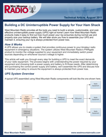
4. PRESENTATION.4.3.1. Normal Mode4.1. SYSTEM CONFIGURATIONThe Modular UPS is configured by the following part: Powermodules, Bypass & Monitoring module, and cabinet with manual Bypass switch. One or several battery strings should beinstalled to provide backup energy once the utility fails. TheUPS structure is shown in Fig. 1.The inverter of power modules continuously supply the criticalAC load. The rectifier/charger derives power from the AC mainsinput source and supplies DC power to the inverter while simultaneously FLOAT or BOOST charging its associated backupbattery.Manual BypassStatic BypassManual BypassBypassStatic rgerDC/DCCharge/Discharge.4.3.2. Battery ModeFig. 1. UPS Configuration4.2. POWER MODULEThe power module structure is shown as Fig. 2. The power module contains a rectifier, an inverter, and a DC/DC converter forcharge and discharge of the external batteries.BatteryBatteryOutputFig. 3. Normal mode operation ssUpon failure of the AC mains input power, the inverter ofpower modules, which obtain power from the battery, supplythe critical AC load. There is no interruption in power to thecritical load upon failure. After restoration of the AC mainsinput power, the” Normal mode” operation will continueautomatically without the necessity of user intervention.Manual BypassRectifierAC/DCInverterDC/ACOutputDC/DCFig. 2. Power module structure4.3. OPERATION MODEThe Modular UPS is an on-line, double-conversion UPS thatpermits operation in the following modes: Normal mode Battery modeStatic OutputDischargeDC/DCFig. 4. Battery mode operation diagramNote:With the function of Battery cold start, the UPS may start withoututility. See more detail in Cold Stard section. Bypass mode Maintenance mode (manual bypass) ECO mode Auto-restart mode Frequency Converter modeMANUAL DE USUARIOADAPT SISTEMA DE ALIMENTACIÓN ININTERRUMPIDA7
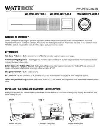
4.3.3. Bypass ModeManual BypassIf the inverter overload capacity is exceeded under Normal mode,or if the inverter becomes unavailable for any reason, the statictransfer switch will perform a transfer of the load from the inverterto the bypass source, with no interruption in power to the criticalAC load. Should the inverter be asynchronous with the bypass, thestatic switch will perform a transfer of the load from the inverterto the bypass with power interruption to the load. This is to avoidlarge cross currents due to the paralleling of unsynchronized ACsources. This interruption is programmable but typically set to beless than 3/4 of an electrical cycle, e.g., less than 15ms (50Hz) orless than 12.5ms (60Hz). The action of transfer/re-transfer can alsobe done by the command through monitor.Manual ChargerDC/DCFig. 7. ECO Mode operation diagramNote:The battery may become exhausted following an extendedAC mains failure. The inverter shuts down when the batteryreaches the End of Discharge Voltage (EOD). The UPS maybe programmed to “System Auto Start Mode after EOD”. Thesystem starts after a delay time when the AC mains recovers.The mode and the delay time are programmed by the commissioning engineer.4.3.4. Maintenance Mode (Manual Bypass)A manual bypass switch is available to ensure continuity of supplyto the critical load when the UPS becomes unavailable e.g. duringa maintenance procedure. (See Fig. 6).Manual BypassStatic BypassRectifierAC/DCBatteryInverterDC/AC4.3.6. Auto-restart ModeFig. 5. Bypass mode operation ainThere is a short interruption time (less than 10ms) whentransfer from ECO mode to battery mode, it must be sure thatthe interruption has no effect on loads.Static BypassBypassStatic BypassBypass4.3.7. Frequency Converter ModeBy setting the UPS to Frequency Converter mode, the UPS couldpresent a stable output of fixed frequency (50 or 60Hz), and thebypass static switch is not available.4.4. UPS STRUCTUREInverterDC/ACOutput4.4.1. UPS ConfigurationThe UPS configuration is provided in Table 1BatteryChargerDC/DCFig. 6. Maintenance mode operation diagramDanger:During Maintenance mode, dangerous voltages are present onthe terminal of input, output and neutral, even with all the modules and the LCD turned off.4.3.5. ECO ModeTo improve system efficiency, UPS rack system works in Bypassmode at normal time, and inverter is standby. When the utility fails, the UPS transfers to Battery Mode and the inverterpowers the loads.8SALICRU
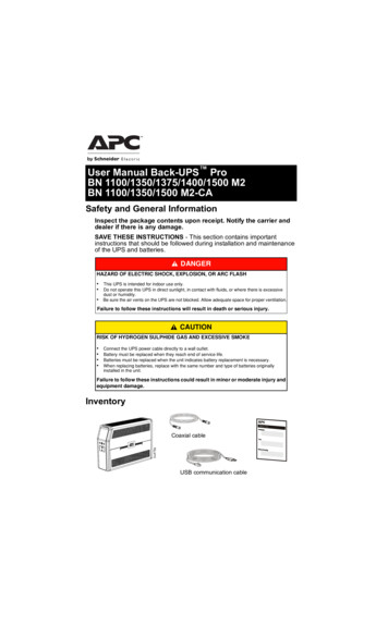
ItemCabinetPower moduleComponentsQuantity/ pcsRemarkManual Bypass1Requisite, factory installedSystem display1Requisite, factory installedBypass & Monitoringmodule1Requisite, factory installedDust filter1Optional.Power module1-10Requisite, installed on site.Table 1. UPS Configuration.System UnitPowerConnectionBypassMoudlePowerModuleFig. 8. 10 module cabinet UPS StructureSystem UnitPowerConnectionBypassMoudlePowerModuleFig. 9. 6 module cabinet UPS StructureMANUAL DE USUARIOADAPT SISTEMA DE ALIMENTACIÓN ININTERRUMPIDA9
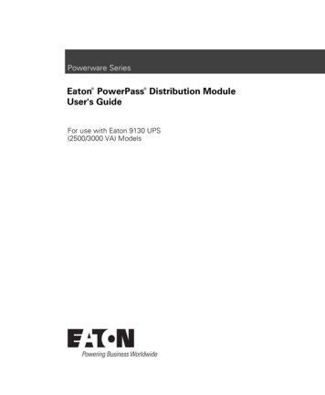
SurgeProtectionSystem UnitPowerConnectionBypassMoudlePowerModuleFig. 10. 3 module cabinet UPS Structure10SALICRU
5. INSTALLATION INSTRUCTIONIf external batteries are to be used, the battery circuit breakers(or fuses) must be mounted as close as possible to the batteries, and the connecting cables should be as short as possible.5.1. LOCATIONAs each site has its requirements, the installation instructionsin this section are to act as a guide for the general proceduresand practices that should be observed by the installing engineer.5.1.1. Installation EnvironmentThe UPS is intended for indoor installation and uses forcedconvection cooling by internal fans. Please make sure there isenough space for the UPS ventilation and cooling.Keep the UPS far away from water, heat and inflammable andexplosive, corrosive material. Avoid installing the UPS in theenvironment with direct sunlight, dust, volatile gases, corrosivematerial and high salinity.Avoid installing the UPS in the environment with conductivedirt.The operating environment temperature for battery is 20ºC25ºC. Operating above 25ºC will reduce the battery life, andoperation below 20ºC will reduce the battery capacity.5.1.2. Site SelectionEnsure the ground or installation platform can bear the weightof the UPS cabinet ,batteries and battery rack.No vibration and less than 5 degree inclination horizontally.The equipment should be stored in a room so as to protect itagainst excessive humidity and heat sources.The battery needs to be stored in dry and cool place with goodventilation. The most suitable storage temperature is 20 ºC to25ºC.5.1.3. Size and WeightThe size of three views for the UPS cabinet is shown in Fig. 11.Attention:Ensure there is at least 0.8m before the front of the cabinet soas to easily maintain the power module with the front door fullyopen and at least 0.5m behind for ventilation and cooling.The battery will generate a little amount of hydrogen andoxygen at the end of charging; ensure the fresh air volume ofthe battery installation environment must meet EN50272-2001requirements.ModuleUnitsDimensions WxDxHmmWeightKg101520590 x 440 x 1342122.522.5Table 2. Module mechanical 90/15,120/20100/10,150/15, 200/20Dimensions g120151182Table 3. System mechanical characteristics.MANUAL DE USUARIOADAPT SISTEMA DE ALIMENTACIÓN ININTERRUMPIDA11
Fig. 11. Dimensions 120KVA.Fig. 12. Dimensions 60KVA.12SALICRU
Fig. 13. Dimensions 200KVA.MANUAL DE USUARIOADAPT SISTEMA DE ALIMENTACIÓN ININTERRUMPIDA13
5.2. UNLOADING AND UNPACKING5.2.1. Moving and Unpacking of the CabinetThe steps to move and unpack the cabinet are as follows:1. Check if any damages to the packing. (If any, contact to thecarrier)2. Transport the equipment to the designated site by forklift,as shown in Fig. 14.Fig. 16. Remove the protective foam5. Check the UPS.a. Visually examine if there are any damages to UPSduring transportation. If any, contact to the carrier.b. Check the UPS with the list of the goods. If any itemsFig. 14. Transport to the designated site3. Open the top plate of the steel-edged wooden case withslotted awl and pier, followed by side boards (see Fig. 15).are not included in the list, contact to our company orthe local office.6. Dismantle the bolt that connects the cabinet and woodenpallet after disassembly.7. Move the cabinet to the installation position.Attention:Be careful while removing to avoid scratching the equipment.5.2.2. Unpacking Power Module1. The steps to move and unpack the power module are asfollows:2. The packing case must be placed on the platform smoothly,as is shown in Fig. 17.Fig. 15. Disassemble the case4. Remove the protective foam around the cabinetFig. 17. Place on platform smoothly3. Cut the plastic packing belt and scotch tape to open thecarton. (See Fig. 18).14SALICRU
121- Carton2- Foam packingFig. 18. Open the carton4. Remove the foam cover (See Fig. 19).1- Carton2- Foam packing3- Power moduleFig. 19. Remove the foam cover.5. Take out the UPS with plastic package and dismantle thepackaging materials.Attention:The waste materials of unpacking should be disposed to meetthe demand for environmental protection.MANUAL DE USUARIOADAPT SISTEMA DE ALIMENTACIÓN ININTERRUMPIDA15
6. POSITIONING6.1. POSITIONING CABINETThe UPS cabinet has two way of supporting itself: One is to support itself temporarily by the four wheels at the bottom, makingit convenient to adjust the position of the cabinet; The other isby anchor bolts to support the cabinet permanently after adjusting the position of the cabinet. The supporting structure isshown in Fig. 20.6.2. INSTALLING POWER MODULEThe installation position of power module is shown in Fig. 21.Please install the power modules following the principle offrom bottom to top to prevent inclination of the cabinet due tohigh center of gravity. The steps of installing power module areas follows:1. Ensure the cabinet is fixed and no damage to the body andinserting port of the power module.2. Hold the handler and the body of the power module by twopersons at each side.3. Insert the module in the installation position, and push itinto the cabinet smoothly.4. Fix the module to the cabinet though the mounting holeson two sides of the front plate of the module (See Fig. 21right).5. Installing Power Module done.1- Anchor bolts2- WheelsFig. 20. Supporting structure (Bottom view).The steps to position the cabinet are as follows:1. Ensure the supporting structure is in good condition and themounting floor is smooth and strong.2. Retract the anchor bolts by turning them counterclockwiseusing wrench, the cabinet is then supported by the fourwheels.3. Adjust the cabinet to the right position by the supportingwheels.4. Put down the anchor bolts by turning them clockwise usingwrench, the cabinet is then supported by the four anchorbolts.5. Ensure the four anchor bolts are in the same height and thecabinet is fixed and immovable.6. Positioning done.Attention:Auxiliary equipment is needed when the mounting floor is notsolid enough to support the cabinet, which helps distribute theweight over a larger area. For instance, cover the floor with ironplate or increase the supporting area of the anchor bolts.161-Bypass module2- Power module3-10# Power module4- 2# Power module5- 1# Power module6- Mounting holesFig. 21. Installing power moduleSALICRU
Note:The installing method of bypass module is the same as thepower module.6.3. BATTERYThe battery set can be based between 36 and 44 blocks connected in serial, but it will always be an even number due tothe internal structure of the equipment, which needs a mid tapor central point (neutral) of them. At the same time, the back uptime together with the required power to feed the loads establishes the needed capacity of the battery in Ah.In Fig. 22, “N” means the total quantity of battery blocks connected in serial, being able to select it among the figures abovestated.Fig. 22. Battery string wiring diagram1- Signal Cables2- Power Cables3- Blanking plateFig. 23. Cable entryDanger:The battery terminal voltage is of more than 400Vdc, pleasefollow the safety instructions to avoid electric shock hazard.Ensure the positive, negative, neutral electrode is correctly connected from the battery unit terminals to the breaker and fromthe breaker to the UPS system.6.4. CABLE ENTRYCables can enter the UPS cabinet from the top. Cable entry ismade possible through a blanking plate fitted at the top of theequipment. The cable entry is shown in Fig.23.6.5. POWER CABLES6.5.1. SpecificationsThe «Recommended installation» information for each inputand output setting is available with the supplieddocumentation, manual and/or CD. In that information is shown thecircuit diagram, as well as the protection size and minimum crosssection of the wires that are connected to the equipment, taking intoaccount the nominal operating voltage. All figures are calculated fora maximum total cable length of 30 m between the distributionpanel board, equipment and loads. For longer lengths correct the cross sections accordingly,in order to avoid dropping voltages, by respecting theRegulations or norms corresponding to the country. In the own documentation and for each setting, it isavailable the information for «N» units in parallel, as wellas the features of the own «Backfeed protection».Attention:The CB with RCD (Residual Current Device) is not suggested for the system.MANUAL DE USUARIOADAPT SISTEMA DE ALIMENTACIÓN ININTERRUMPIDA17
6.5.2. Connecting Power CablesThe steps of connecting power cables are as follows:1. Verify that all the external input distribution switches of theUPS are completely open and the UPS internal maintenancebypass switch is opened. Attach necessary warning signsto these switches to prevent unauthorized operation.2. Open the back door of the cabinet, remove the plasticcover. The input and output terminal, battery terminal andprotective earth terminal are shown in Fig. 23.Attention :The operations described in this section must be performed by authorized electricians or qualified technical personnel. If you have any difficulties, contact the manufactureror agency.Warning : Tighten the connections terminals to enough torquemoment, and please ensure correct phase rotation. The grounding cable and neutral cable must be connectedin accordance with local and national codes.6.6. CONTROL AND COMMUNICATION CABLESThe front panel of the bypass module provides dry contact interface (J2-J11) and communication interface (RS232, RS485,SNMP ,Intelligent card interface and USB port), as it is shownin Fig. 27.Fig. 24. Power Connection of Module System UPS: 200KVAUPS power connectionFig. 27. Bypass Module (Include Interface of Dry ContactBoard GJ and Monitoring Board FK)6.6.1. The UPS dry contact board GJ provides input drycontacts and output dry contacts Dry Contact Interface of Battery and EnvironmentalTemperature DetectionFig. 25. Power Connection of Module System UPS: 120KVAUPS power connectionThe input dry contact J2 and J3 detect the temperature ofbatteries and environment respectively, which can be used inenvironment monitoring and battery temperature compensation.Fig. 26. Power Connection of Module System UPS: 60KVAUPS power connectionFig. 28. Diagram of J2 and J3 Dry Contact of TemperatureDetection3. Connect the protective earth wire to protective earthterminal (PE).4. Connect the AC input supply cables to the Main Inputterminal and AC output supply cables to the Output terminal.5. Connect the Battery cables to the Battery terminal.6. Check to make sure there is no mistake and re-install all theprotective covers.NamePurposeJ2.1TEMP BATBattery temperature detectionJ2.2/Battery temperature detectionJ3.1TEMP ENVEnvironment temperature detectionJ3.2/Environment temperature detectionPositionSpecified temperature sensor is required for temperature detection (R25 5Ohm,B25/50 3275), please confirm with the manufacturer, or contact localmaintenance engineers when placing an order.Table 4. Description of Input Dry Contact18SALICRU
Remote EPO Input PortThe UPS has an Emergency Power OFF (EPO) function. Thisfunction can be activated by pressing a button on the controlpanel of the UPS or through a remote contact provided by theuser. The EPO pushbutton is protected by a hinged plastic cover.J4 is the input port for remote EPO. It requires shorting NC and 24v during normal operation, and the EPO is triggered whenopening NC and 24v, or shorting NO and 24v.Fig. 30. Diagram of aux. contact external manual bypassMCBNamePurposeJ5.1 24VInternal 24V power supplyJ5.2GENConnection status of generatorJ5.3GNDPower groundPositionFig. 29. Description of Input Dry Contact for Remote EPOPositionNamePurposeJ4.1EPO NCEPO is activated when disconnecting fromJ4.2J4.2 24V 24V, connect the common terminal of NCand NOJ4.3EPO NOEPO is activated when shorting with J4.2Table 5. Description of Input port for Remote EPOTable 6. Description of Status Interface and Connectionof Generator BCB Input PortThe default function of J6 and J7 are the ports of BCB. Theport diagram is shown in Fig. 31, and description is shown inTable 7. Aux. contact external manual bypass Input Dry Con-tactThe default function of J5 is the interface for external manualbypass J5 Connect pin 2 of J5 with 24V power supply; itindicates that the external manual bypass MCB has beenconnected and the load are supplied the mains. The interfacediagram is shown in Fig. 30, and interface description is shownin Table 6.Fig. 31. BCB InterfacePositionNameDescriptionJ6.1BCB DRVBCB actuating signal, provide the actuatingsignal of 24V, 20mAJ6.2BCB CONTBCB contact status, connect with the normallyopen signal of BCBJ7.1GNDCommon connectionBCB ONLBCB on-line–input (normally open) , BCB ison-line when the signal is connecting withcommon connectionJ7.2Table 7. Description of BCB InterfaceMANUAL DE USUARIOADAPT SISTEMA DE ALIMENTACIÓN ININTERRUMPIDA19
Bypass Output Dry Contact Interface .The default function of J8 is the bypass output dry contactinterface. The interface diagram is shown in Fig. 32, anddescription is shown in Table 8.NamePurposeJ9.1ALARM NCIntegrated warning relay (normally closed) willbe open during warningJ9.2ALARM NOIntegrated warning relay (normally open) willbe closed during warningJ9.3GNDCommon connectionPositionTable 9. Description of BCB Interface Utility Fail Warning Output Dry Contact InterfaceThe default function of J10 is the output dry contact interfacefor utility failure warning, when the utility fails, the systemwill send a utility failure warning information, and providean auxiliary dry contact signal via the isolation of a relay. Theinterface diagram is shown in Fig. 34, and description is shownin Table 10.Fig. 32. Battery Low Warning Dry ContactNamedescriptionJ8.1BAT LOWNCBattery warning relay (normally closed) will beopen during warningJ8.2BAT LOWNOBattery warning relay (normally open) will beclosed during warningJ8.3GNDCommom connectionPositionTable 8. Battery warning dry contact interfacedescription General Alarm Output Dry Contact InterfaceThe default function of J9 is the general alarm output drycontact interface. When one or more warnings are triggered, anauxiliary dry contact signal will be active via the
9.9. UPS EVENT LOG 10. OPERATIONS 10.1. INTRODUCTION 10.2. UPS STARTUP 10.2.1. Start-Up Procedure 10.2.2. Battery Start 10.3. PROCEDURE FOR SWITCHING THE UPS BETWEEN MAINTENANCE BYPASS AND NORMAL MODE 10.3.1. Switch from normal mode to bypass mode 10.3.2. Switch from bypass mode to normal mode 10.3.3. Switch from Normal Mode to Maintenance .