Transcription
Rotary UPS and GensetsTotally flexible and high efficiencyUPS configurations
Contents1Introduction . 32Characteristics of modern Rotary UPS . 33Bridging time . 64Various UPS and Diesel combinations . 75Functional aspects of combining Rotary UPS with Gensets. 96Arrangements of RUPS and Gensets . 12Diesel generators located upstream of the UPS.12Diesel Rotary UPS (DRUPS) .14Rotary UPS with Diesel Generators connected downstream . 147Summary . 178References . 172
1 IntroductionTo protect mission critical facilities against power outages the installation of uninterruptiblepowers supplies (UPS) is the standard method. Usually long and short term outages need tobe bridged and so UPS systems are complemented with external Diesel generators ordirectly combined with a diesel engine in a Diesel Rotary UPS (DRUPS). The combination ofRotary UPS (RUPS) and external Diesel generators is a tried and tested solution with aninstalled base of approaching 1000 MVA. Because of the distinct advantages with thiscombination, some of the most recent high profile and major Tier III and Tier IV data centresuse this technology. With the latest release of RUPS, the system designer can realise anunprecedented multiple of configurations in conjunction with extremely high efficiencies evenat the lower loads often encountered in early-life data centres.This paper focusses on the general requirements for a Diesel Generator to be combined withRotary UPS and shows a variety of combinations that provide an increased maintainability aswell as an extended choice of engines and can be realized in low voltage as well as inmedium voltage.Additionally the paper describes how the Diesel generator can be integrated into the controlsof a Rotary UPS to build a powerful and multifunctional system, which is named a DeRUPS(Diesel electrically coupled Rotary UPS). This integration allows the use of external Dieselgenerators in more complex designs like IP-Systems[1] while keeping the advantages comingwith the physical separation of UPS and Diesel.2 Characteristics of modern Rotary UPSThe modern Rotary UPS combines the highest possible reliability with extremely highefficiencies and a choice of ride-through energy store. Their routine maintenance regime issimple and relatively non-intrusive when compared with Static UPS solutions.Reliability: Rotary UPS do have the most simple and most reliable method of powergeneration using synchronous machines. This operating principle in combination with up-todate digital electronic controls and user interfaces results in the highest reliability for anysingle UPS available on the market today.3
Efficiency & Cost: The modern Rotary UPS uses advanced materials and designs toachieve an operating efficiency of up to 97% with low load efficiencies as high as 95%. Dueto the low losses and robust design, RUPS often do not require any active cooling deviceslike air conditioning which makes operation even more cost effective over the system life.Fig. scounted cash-flow)Although the day 1 investment in a Rotary system can sometimes be more than that of thestatic option, the reduced complexity of routine maintenance, extended life and highoperating efficiency of the Rotary all contribute to reduce the total ownership costs andproduce a break-even point within just a few years.Flexibility: The topology allows the Rotary UPS system to be employed readily either at lowor at medium voltage and to utilise either batteries or flywheel as the energy store for smalland large unit sizes alike.The combination of RUPS with kinetic energy storage devices like flywheels result in amassively reduced footprint compared to any battery-based systems. This makes asignificant amount of additional floor space available that can be used for other equipment orto increase net useable technical/production floor space.4
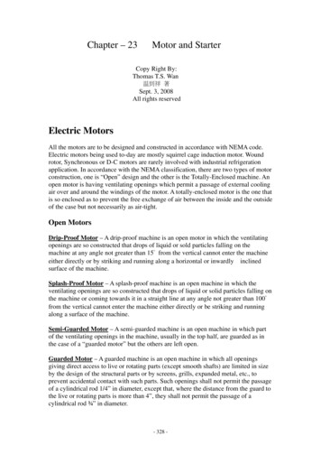
Rotary UPS can easily be paralleled to increase the total power or to achieve redundancy.There are no ultra-fast and complex regulation structures necessary as the paralleling ofsynchronous generators is based on strong, self-effective synchronizing powers.Because of utilizing synchronous generators certain Rotary UPS are able to deliver full activepower from power factor 0.8 lagging to 0.8 leading without the necessity of de-rating atleading power factors. Their short circuit capacity of 12x-14x nominal current allows easydiscrimination in the downstream distribution and eliminates the necessity of bypasstransfers to clear a downstream fault.Totally flexibleconfigurations,Medium andLow VoltageHigh load-carryinggenerator with a robust,highly efficient designFlywheelfor up to 39sshort backupFig. 2Customisedbattery forshort backupSome features of modern Rotary UPS and their flexibilityAll of this demonstrates a high suitability and benefit with Rotary UPS for high endapplications in which reliability balanced with ownership costs really matters. For that reasonmany large international data centres, banks, continuous process facilities and hospitals relyon Rotary UPS and stay with this technology through clear choice if new systems need to beinstalled.5
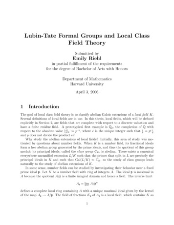
3 Bridging timeAccording to the statistics more than 96% of the mains outages have durations of less thanthree seconds.Fig. 3Mains failure statistic of a medium voltage gridThe practical bridging times of energy stores are:Flywheels:0 s 30 secondsBatteries:0 s 30 minutes.Diesel generators: 10s HoursComparing these figures with the statistics about mains failures shows that pure flywheelUPS are able to cover more than 96% of all mains outages. Battery UPS would – dependingon the battery size – be able to bridge approximately another 3%. A stand-alone Dieselgenerator is not able to bridge the first 10 seconds of a mains failure so to be sure to coverall kinds of mains failures a combination of one short term energy storage and a long termbridging device like a Diesel generator is mandatory. The question of whether a combinationof a battery UPS and a Diesel generator really makes sense in considering that the bridgingtime of a flywheel is sufficient to ensure the engine start, is a well known subject ofdiscussion and dealt with in another paper[2].6
4 Various UPS and Diesel combinationsFig. 4 shows the typical arrangement of a UPS and a Diesel generator in which the Dieselgenerator functions as a mains substitute after utility failure. This layout is typically chosenfor a Static UPS solution. Since the inverters normally used in Static UPS are not designed tooperate bi-directionally this is the simplest way to charge the energy storage during Dieseloperation. If the Static UPS is operated in double conversion mode1 frequency fluctuations ofthe Diesel are not transferred to the load side of the UPS and harmonics produced by theloads are not transferred to the generator. However, operating the Static UPS in ECO modewill increase its efficiency but adds the drawbacks of unfiltered harmonics on the generator,no power factor correction at the input of the UPS and frequency variations of the Diesel.No Break LoadsMainsDFig. 4GA typical combination of a Static UPS with batteries and a Diesel generatorThis mode of operation is something certain modern Rotary UPS do not have to strugglewith. In mains as well as in Diesel operation they are running with the same high efficiency,guaranteeing power factor correction and harmonic filtering at the same time.Additionally and in contrast to conventional Static UPS, a RUPS offers a much wider varietyof combinations with Diesel engines. One such combination is the Diesel Rotary UPS(DRUPS), in which the Diesel engine, like it is shown in Fig. 5, directly drives the generator ofthe Rotary UPS. During a mains failure the load is first supplied by the short term energystorage, which can be a battery or a flywheel. Then the Diesel just needs to start and oncethe Diesel reaches nominal speed the overrunning clutch between the engine and thepermanently rotating generator closes automatically.rotating generator closes automatically.1In double conversion mode the power is transferred through rectifier and inverter.7
MainsNo Break LoadsGM/GDorShort Break LoadsMainsFig. 5A Diesel Rotary UPS (DRUPS):The Diesel directly drives the internal generator via an overrunning clutch. Ifthe Rotary UPS utilizes a combined motor/generator, the short breaksloads can be supplied by the motor winding of the electrical machine,alternatively the short-break loads can be supplied from the UPS outputbus.But of course a Rotary UPS can also be combined with external Gensets. The combinationof Rotary UPS with electrically coupled Diesel generators is called DeRUPS and offers onemore interesting variant than simply using the Genset as a mains replacement. With RotaryUPS it is also possible to connect the Genset to the output bus of the UPS. This offers someadvanced features regarding power sharing, frequency stabilization and maintainability.MainsDNo Break LoadsGGM/GorMainsShort Break LoadsMainsNo Break LoadsGM/GGDorMainsFig. 6DeRUPS: Rotary UPS in combination with Gensets, which can either belocated upstream or downstream.8Short Break Loads
Each external Genset basically allows supplying the no-break loads as well as short-breakloads (Fig. 6). If the Genset is connected to the input of the UPS the no-break and the shortbreak loads remain isolated also in Diesel operation, a feature that is quite welcome in theworld of data centres.Since almost all Rotary UPS are also available in a medium voltage version, all combinationswith external Gensets can also be realized in medium voltage. In this case the Gensets canbe equipped with medium voltage generators if the voltage level does not exceed thetechnical limits for these machines.5 Functional aspects of combining Rotary UPS with GensetsA general aspect that needs to be considered when combining any UPS with a Dieselgenerator is the interaction between the two power sources, namely the energy storage ofthe UPS and the Diesel engine. This interactions finally makes the difference between asimple combination of any UPS with a Diesel Generator and a DeRUPS (Electrically coupledDiesel Rotary UPS) in which the Genset is totally integrated in the functional behaviour of theUPS. To understand this interaction it is helpful to differentiate between active power sourcesand reactive power sources, as it is shown in Fig. 7.Active PowerReactive PowerM/GBatteryFig. 79PowerbridgeRelationships between power sources and power type
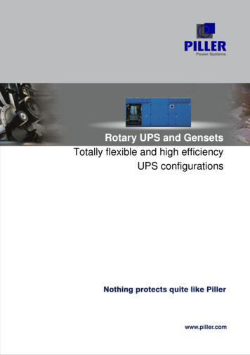
Independent of whether the Diesel generator is connected upstream or downstream of theUPS, the Diesel engine needs to be able to deliver the active power for the load, to chargethe energy store and to cover the losses of the UPS. The generator of an upstream Gensetneeds to supply the current taken by the UPS. It also needs to be able to supply the reactivepower taken by the UPS and to deal with the harmonics of potential rectifier circuits in theinput of the UPS. Due to their natural sine wave generation, Rotary UPS do not create anyharmonics and their input power factor is close to 1.0.Having the Genset connected downstream can be slightly more efficient because this avoidsforward losses in the UPS during Diesel operation. The exchange of reactive power betweenthe UPS and the generator needs to be avoided by utilizing reactive currents controls. It isbest practice that either the UPS or the Genset supplies reactive power to the load while theother component regulates its reactive power to zero.A UPS with a Diesel generator located upstream of the UPS normally behaves like a UPS inmains operation, even if the supply is a Diesel generator. Therefore the UPS transfers anyload changes to the mains, which is not as stable as in the past. Load steps of between 80%up to 100% can then easily cause the engine to collapse and shut down independent ofwhether this is an on-load or an off-load situation.Certain Rotary UPS with electrically coupled flywheels are able to handle both powerdirections and can therefore stabilize the frequency of a Diesel generator. In this case it doesnot matter whether the Genset is connected upstream or downstream of the RUPS.However, since the frequency regulation is assigned to the load side of the DeRUPS, theperformance is better if the Genset is connected downstream.The comparison of Fig. 8 and Fig. 9 as an example shows the influence of bidirectionalfrequency stabilization on a network supplied by a Diesel generator.10
Fig. 8Frequency response of a Diesel generator during 50% load disconnectionand reconnection, here without additional frequency stabilization.Fig. 9Frequency response of a DeRUPS in Diesel operation during 50% loaddisconnection and reconnection, with bidirectional frequency stabilizationby a Piller UNIBLOCK UBT equipped with a POWERBRIDGE flywheelenergy storage device and an external Diesel generator.Additionally an electrically coupled flywheel that can be charged and discharged at the samerate which allows short re-charge times and cuts down Diesel run time with further savings inrunning costs. This is not possible with battery UPS and so this kind of flywheel supportedsystem is well prepared against multiple utility disturbances.11
6 Arrangements of RUPS and GensetsIn the following different arrangements of UPS and Diesel generators are compared.Diesel generators located upstream of the UPS.Upstream Diesel generators are used to operate as a mains substitute during a mainsoutage. They can either operate in a parallel manner feeding a common bus to supplyseveral UPS or, in the case of large UPS units, each can be assigned to a single UPS. If theDiesel generators are paralleled it is best practice if they feed an isolated bus that can beconnected to the UPS input bus via a central breaker, like it is shown inFig.11.The separated Genset bus also allows starting the Gensets via start up synchronisation, alsoknown as dead bus synchronisation. As in this case all Gensets start while already beingconnected to the bus, there is no extra synchronisation time for the individual Gensets to beconsidered. Combined with high quality Genset controls containing this special functionalitythis start method allows shortest start times and guarantees that the load can reliably besupplied by the Gensets even if UPS with flywheel energy storage are used.MainsGensetsMMMMMGSGenset breaker(s)GSMMMMGSMMMains Breaker GG(Genset) Group BreakerMto UPSFig. 1012Example of Genset controls suited to perform start up synchronisation
Once all Gensets are started and feeding their collecting bus, the central breaker will beclosed to energize the UPS input bus. This prevents the UPS to return to ‘mains’ as longs asnot all Gensets are ready to feed the bus. This central breaker does have a counterpart inthe mains feeder both building a breaker pair which easily allows a synchronized changeoverto utility once mains is available dsFig. 11A set of Diesel generators feeding the incoming bus of a group of RotaryUPS, which can be operated in a stand alone as well as in a parallelconfiguration.An advantage of this arrangement is that the number of Diesel engines can be different tothe number of UPS, even though redundancy of Diesel generators also needs to beconsidered.Maintenance on the Gensets can be done independently from UPS maintenance, rangement.As a fallback the Diesel generators are able to permanently supply the loads via the UPSmaintenance bypass which can be an interesting feature in countries with a really bad mainsquality.13
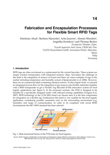
Diesel Rotary UPS (DRUPS)The one big advantage of this system is that the Diesel engine isalso mechanicallyintegrated into the UPS functionality. Therefore no extra controls for synchronization orbreaker operation are necessary, as it is for external Genset arrangements. The redundancyis naturally the same for the UPS and the Diesel engines as the number of UPS and Diesel isequal.IncomingpowerDM/GGDM/GDGM/GGDM/GGLoadsFig. 12A power supply arrangement containing Diesel Rotary UPS (DRUPS).During maintenance always the whole UPS including its Diesel engine needs to be taken outof service.Rotary UPS with Diesel Generators connected downstreamHaving Gensets connected to the load side of the UPS is a less familiar method since mostStatic UPS are not able to handle this situation. Fig. 13 shows a possible configuration whichcomes along with some advantages worth consideration.14
M/GM/GGM/GGM/GGGDDDDGGGGLoadsFig. 13A group of Rotary UPS each combined with a Genset connected to the loadside.In this configuration it is necessary to control the power sharing between the energy storageof the UPS and the Diesel generator. This power sharing capability is then used to shift thepower that the UPS feeds to the load right after the mains failure to the Diesel generatoronce it is started and connected to the load bus. This functionality, which makes thecombination of RUPS and Genset being a real DeRUPS, is already implemented in certainmodern Rotary UPS and does also allow charging the energy store of the UPS during Dieseloperation. In case of a bi-directional operating energy storage device like an electricallyconnected flywheel, the energy store can then be used to keep a stable output frequency.This is realized by having the flywheel delivering power in the case of on-load events until theDiesel has taken over as well as in the case of off-load events having the flywheel absorbingsuperfluous power from the Diesel until it is throttled down. Because of this interaction theDeRUPS is also able to control all synchronization processes like, for example, the return ofthe DeRUPS into mains operation once utility is available. As for upstream connectedGensets, it is not strictly necessary to have one Genset assigned to one RUPS as it is alsopossible to have different numbers of RUPS and Gensets combined while keeping the samefunctionality. The DeRUPS is also well suited to be implemented into an IP-System. Fig. 14shows an example of such combination.15
DDGGM/GM/GGGNo-Break-LoadFig. 14Short-Break-LoadDeRUPS integrated in an IP-System.Here the extra power of the Genset is also used to supply the short-breakloads.Another advantage of having the Diesel generators connected downstream of the RUPS isthat they can be operated independently of the UPS if necessary. Therefore maintenance ona Genset can be done separately from UPS maintenance based on the Gensets owncontrols coming along with each individual Genset. During maintenance of the Genset theload can still have short term protection by the RUPS which normally bridges almost all of themains outages without Diesel Fig. 15Diesel generators separated from the UPS allow individual maintenance oneach type of power supply keeping the remaining system functional.16
7 SummaryA combination of UPS and Diesel generators can be much more than simply using theGensets as a mains substitute. Besides this variant which is typical for a combination ofStatic UPS with Gensets, Rotary UPS offer a much wider variety of combinations withsuperior load handling characteristics, reliability and ownership costs. Compared to the wellknown Diesel Rotary UPS the combination of a Rotary UPS with a separated Dieselgenerator connected to the load side offers some interesting features. The possibility tooperate the Diesel generator and the RUPS independently offers enhanced maintainabilitywhile the combination of both guarantees outstanding frequency stability even in Dieseloperation. The combination of high efficiency and low operating costs with configurationflexibility and pre-eminent reliability makes the Rotary UPS and Genset pair a highlydesirable offering for large-scale project designs.8 References[1] Dipl.-Ing. Frank HerbenerIso-Parallel UPS ConfigurationPiller White Paper 051, 2009[2] Dipl.-Ing. Frank HerbenerBatteries and FlywheelsPiller White Paper 056, 2011Piller Group GmbH,Frank.Herbener@piller.com, GermanyWhite Paper No. 0061-1 / Apr 201317
the UPS and the generator needs to be avoided by utilizing reactive currents controls. It is best practice that either the UPS or the Genset supplies reactive power to the load while the other component regulates its reactive power to zero. A UPS with a Diesel generator located upstream of the UPS normally behaves like a UPS in