Transcription
USER MANUALUNINTERRUPTIBLE POWER SUPPLIES (UPS)SLC TWIN PRO2 T UL6 and 10 kVA
General index1. INTRODUCTION.5.2. CONNECTIONS.1.1. THANK YOU LETTER.5.2.1. Connection of the input terminals to the AC mains.2. SAFETY INFORMATION.5.2.2. Connection of the load or loads to the output terminals.2.1. USING THIS MANUAL.5.2.2.1. Output configurations depending on the connection ofthe secondary windings of the isolation transformer.2.1.1. Conventions and symbols used.3. QUALITY ASSURANCE AND STANDARDS.5.2.3. Connection to the external batteries and backupextension.3.1. STATEMENT BY THE MANAGEMENT.5.2.4. Connection of the earth bonding terminal3.2. STANDARDS.5.2.5. Terminals for EPO (emergency power off).3.3. ENVIRONMENT.5.2.6. Parallel connection.4. PRESENTATION.5.2.6.1. Introduction in redundancy.4.1. VIEWS.5.2.6.2. Installation and parallel operation.4.1.1. Views of the device.5.2.7. RS-232 and USB communications port4.2. DEFINITION OF THE PRODUCT.5.2.8. Smart slot for the integration of an electroniccommunication unit.4.2.1. Nomenclature.4.3. OPERATING PRINCIPLE.4.3.1. Notable features.5.2.9. Software.5.2.10. Considerations before startup with connected loads.4.4. OPTIONAL EXTRAS.6. OPERATION.4.4.1. Exterior manual maintenance bypass.6.1. STARTUP.4.4.2. Communication card.6.1.1. Checks before startup.4.4.2.1. Integration into computer networks using an SNMPadapter.6.2. UPS STARTUP AND SHUTDOWN.4.4.2.2. RS-485 modbus.6.2.2. UPS startup without mains voltage.4.4.2.3. Relay interface.6.2.3. UPS shutdown with mains voltage.5. INSTALLATION.6.2.4. UPS shutdown without mains voltage.5.1. RECEPTION OF THE DEVICE.6.3. MANUAL BYPASS SWITCH (MAINTENANCE).5.1.1. Reception, unpacking and contents.6.3.1. Transfer to maintenance bypass.5.1.2. Storage.6.3.2. Transfer to normal operation.5.1.3. Unpacking.6.4. OPERATING PROCEDURE FOR A PARALLEL SYSTEM.5.1.4. Transport to the site.6.5. HOW TO INTEGRATE A NEW UPS INTO ANOPERATIONAL PARALLEL SYSTEM, OR A UPS INSINGLE MODE.5.1.5. Siting, immobilising and considerations.5.1.5.1. Siting for single devices.5.1.5.2. Siting for parallel systems.6.2.1. UPS startup with mains voltage.6.6. HOW TO REPLACE A FAULTY UPS IN AN OPERATIONALPARALLEL SYSTEM.5.1.5.3. Immobilising the device.5.1.5.4. Preliminary considerations before connection.5.1.5.5. Preliminary considerations before connection,regarding the batteries and their protections.5.1.5.6. Connection elements.2SALICRU
7. CONTROL PANEL WITH LCD.7.1. CONTROL PANEL.7.2. FUNCTIONALITY OF THE LEDS.7.2.1. Audible alarms.7.2.2. Messages shown on the LCD.7.3. MEANING OF THE ABBREVIATIONS SHOWN ON THECONTROL PANEL DISPLAY.7.4. SETTINGS ON CONTROL PANEL WITH LCD.7.4.1. View of the settings menus, according to the parameter1 code.7.5. OPERATING MODE / DESCRIPTION OF STATE.7.6. WARNING OR ALERT CODES.7.7. ERROR OR FAULT CODES.7.8. WARNING OR ALERT INDICATORS.8. MAINTENANCE, WARRANTY ANDSERVICE.8.1. BATTERY MAINTENANCE.8.1.1. Notes for the installation and replacement of thebattery.8.2. UPS TROUBLESHOOTING GUIDE.8.2.1. Troubleshooting guide.8.3. WARRANTY CONDITIONS.8.3.1. Terms of the warranty.8.3.2. Exclusions.8.4. TECHNICAL SERVICES NETWORK.9. ANNEXES.9.1. GENERAL TECHNICAL SPECIFICATIONS.9.2. GLOSSARY.USER MANUALSLC TWIN PRO2 T UL UNINTERRUPTIBLE POWER SUPPLIES (UPS)3
1. INTRODUCTION.1.1. THANK YOU LETTER.We thank you in advance for the trust placed in us in the purchasing of this product. Read this instruction manual carefullyin order to familiarise yourself with its content, since the moreyou know and understand the device the greater your satisfaction, level of safety and optimisation of its functionalities willbe.We remain at your disposal for any additional information orqueries that you may wish to make.Yours sincerely.SALICRUThe device described here is capable of causing significant physical injury if improperly handled. For thisreason, its installation, maintenance and/or repair must becarried out exclusively by our staff or qualified personnel. Although no effort has been spared to ensure that the information in this user manual is complete and accurate,we accept no liability for any errors or omissions that mayexist.The images included in this document are for illustrativepurposes and may not exactly represent the parts of thedevice shown; therefore they are not contractual. However,any divergence that may arise will be remedied or solvedwith the correct labelling on the unit. Following our policy of constant evolution, we reservethe right to modify the characteristics, operationsor actions described in this document without priornotice. Reproduction, copying, assignment to third parties,modification or total or partial translation of thismanual or document, in any form or by any means, withoutprevious written permission by us is prohibited, withthe company reserving full and exclusive property rightsover it. 4SALICRU
2. SAFETY INFORMATION.2.1. USING THIS MANUAL.2.1.1. Conventions and symbols used.The documentation of any standard equipment is available tothe customer on our website for download (www.salicru.com). For devices ‘powered by socket,’ this is the website forobtaining the user manual and ‘Safety Instructions’EK266*08. For devices with ‘permanent connection’ via terminals, aCD-ROM or pen drive containing all necessary informationfor connection and startup, including ‘Safety Instructions’EK266*08, may be supplied with it.Before carrying out any action on the device relating to its installation or startup, change of location, configuration or handling of any kind, carefully read the safety instructions.The purpose of the user manual is to provide information regarding safety and explanations of the procedures for installation and operation of the equipment. Read them carefully andfollow the steps indicated in the order established.Some symbols may be used and appear on the device, batteriesand/or in the context of the user manual.For more information, see Section 1.1.1 of the ‘SafetyInstructions’document EK266*08.Compliance with the ‘Safety Instructions’ is obligatory, with the user being legally responsiblefor observing and applying them.The device is delivered properly labelled for correct identification of each of its parts, which, together with the instructionsdescribed in this user manual, allows installation and startupoperations to be performed in a simple and organised mannerwithout any doubts whatsoever.Finally, once the equipment is installed and operating, it is recommended to save the documentation downloaded from thewebsite, CD-ROM or pen drive in a safe and easy-to-accessplace, for any future queries or doubts that may arise.The following terms are used interchangeably in the documentto refer to: ‘SLC TWIN PRO2 T UL,’ ‘TWIN PRO2 T,’ ‘TWIN T,’ ‘PRO2 T,’‘device,’ ‘unit’ and ‘UPS’ - Uninterruptible power supply.Depending on the context of the phrase, it can refer eitherto the actual UPS itself or to the UPS and the batteries,regardless of whether or not it is all assembled in the samemetal enclosure. ‘Batteries’ or ‘accumulators’ - Bank or set of elementsthat stores the flow of electrons by electrochemical means. ‘T.S.S.’ - Technical Service and Support. ‘Customer,’ ‘installer,’ ‘operator’ or ‘user’ - These areused interchangeably and by extension to refer to the installer and/or operator who will carry out the correspondingactions, and the same person may be responsible for carrying out the respective actions when acting on behalf, orin representation, of the above.USER MANUALSLC TWIN PRO2 T UL UNINTERRUPTIBLE POWER SUPPLIES (UPS)5
3. QUALITY ASSURANCE AND STANDARDS.3.1. STATEMENT BY THE MANAGEMENT.Our goal is customer satisfaction, therefore this Managementhas decided to establish a Quality and Environment Policy,through the implementation of a Quality and EnvironmentalManagement System that will enable us to comply with therequirements demanded in the ISO 9001 and ISO 14001 andalso by our Customers and Stakeholders.Likewise, the management of the company is committed tothe development and improvement of the Quality and Environmental Management System, through: Communication to the entire company of the importanceof satisfying both the customer's requirements as well aslegal and regulatory requirements. The dissemination of the Quality and Environment Policyand the setting of the Quality and Environment objectives. Conducting reviews by the Management. Providing the necessary resources. ELECTROMAGNETIC COMPATIBILITY WARNING(FCC): 3.2. STANDARDS.The SLC TWIN PRO2 T is designed, manufactured and sold inaccordance with Quality Management Standard EN ISO 9001.The EC marking indicates conformity with EU Directives: 2014/35/EU - Low voltage safety.2014/30/EU - Electromagnetic compatibility [EMC]2011/65/EU - Restriction of the use of hazardous substancesin electrical and electronic equipment [RoHS]WARNING CONCERNING BATTERIES (UL): EN-IEC 62040-1. Uninterruptible power supplies [UPS].Part 1.1: Safety requirements. EN-IEC 62040-2. Uninterruptible power supplies [UPS].Part 2: Electromagnetic compatibility [EMC] requirements. WARNING:SLC TWIN PRO2 T UL 6 and 10 kVA. Thisis a category C3 UPS. This is a product forcommercial and industrial application in the secondenvironment; Installation restrictions or additionalmeasures may be necessary to avoid disturbances.It is not appropriate to use this device in basic lifesupport applications [BLS], where a failure of theformer can render vital equipment out of service orsignificantly affect its safety or effectiveness. It is alsonot recommended in medical applications, commercialtransport, nuclear installations, or other applicationsor loads, where a failure of the product can lead topersonal or material damage.The EC declaration of conformity of the product isavailable to the customer upon express request to ouroffices. And UL, CSA and FCC markings in accordance with thespecifications of standards:6SLC TWIN PRO2 T UL 6 and 10 kVA. This UPS has beentested and meets the limits for a Class B digital device, pursuant to the FCC Part 15 standard. These limits are defined toprovide reasonable protection against harmful interferencewhen the device operates in a commercial environment.This device generates, uses and can radiate radio frequencyenergy and, if not installed and used in accordance withthe instruction manual, may cause harmful interferenceto radio communications. Operation of this UPS in aresidential environment may cause harmful interference, inwhich case the user must correct the interference at theirown expense.The manufacturer is not liable in the event of modification or intervention on the device by the user.In accordance with the specifications of harmonised standards: UL 1778CSA C22.2 NO.107.3.-14FCC part 15 Subpart B Maintenance of the batteries must be carried out or supervised by personnel who have knowledge of the batteriesand the necessary precautions.Batteries should not be replaced by the operator or user.When changing batteries, replace them with the same typeand number.Caution:: Do not dispose of batteries in fire, as theymay explode.Caution: Do not open or break apart batteries. Theelectrolyte discharged can be harmful to the skinand eyes. It can be toxic.Caution: Batteries can pose a risk of electrocutionand cause a high short-circuit current. The followingprecautions should be observed when working with them:a. Remove any watches, rings or other metal objects.b. Use tools with insulated handles.c. Wear gloves and rubber boots.d. Do not leave tools or metal objects on top of the batteries.e. Disconnect the power source before connecting or disconnecting the battery terminals.f. Determine whether the battery is accidentally earthed.If so, disconnect the power source. Contact with anypart of a battery that is earthed can cause electrocution.The likelihood of electrocution can be reduced if suchconnections are eliminated during installation andmaintenance (applicable to devices and battery cabinetsthat do not have a power circuit connected to earth).SALICRU
3.3. ENVIRONMENT.This product has been designed to respect the environment andmanufactured in accordance with ISO 14001.Recycling of the device at the end of its useful life:Our company undertakes to use the services of authorised andregulatory companies to treat the set of products recovered atthe end of their useful life (contact your distributor).Packaging:For the recycling of the packaging there must be compliancewith the legal requirements in force, in accordance with thespecific regulations of the country where the device is installed.Batteries:Batteries pose a serious danger to health and the environment.The disposal of them shall be carried out in accordance withthe laws in force.USER MANUALSLC TWIN PRO2 T UL UNINTERRUPTIBLE POWER SUPPLIES (UPS)7
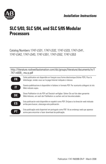
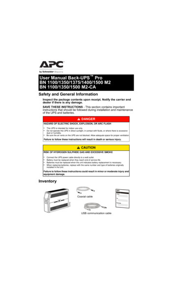
4. PRESENTATION.4.1. VIEWS.4.1.1. Views of the device.Figures 1 and 2 show illustrations of the devices in their singleenclosure format for both powers. However, because theproduct is constantly evolving, discrepancies or slight contradictions may arise. If in any doubt, the labelling on the deviceitself will always prevail.The nameplate of the device shows all of the values relating to its main properties and characteristics. Actaccordingly for its installation.Parallel portCurrent signal bus portUSB portRS-232 portEPO connectorSmart slot coverCharger fanPower stage fansExternal batteryconnector coverMB block screwsMB blockManual bypass -MBInput protectionConnection terminals coverInput/output terminals,see Fig. 9Isolation transformer fanWheel brakeRotating wheelsFig. 1.8Front and rear view of 6 and 10 kVA models.SALICRU
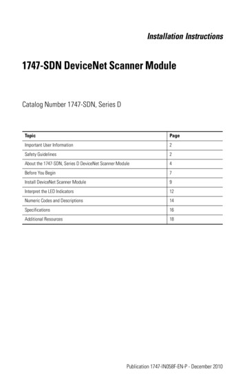
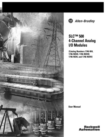
Battery switchBattery connectorprotective coverBattery module with 2x20 elements and 50 Aprotection.Fig. 2.USER MANUALBattery module with 3x20 elements and 50 Aprotection.Rear view of battery modules.SLC TWIN PRO2 T UL UNINTERRUPTIBLE POWER SUPPLIES (UPS)9
4.2. DEFINITION OF THE PRODUCT.4.2.1. Nomenclature.SLC-6000-TWIN PRO2 T B1 UL WCO 0/AB147 208V EE521925EE521925208V147AB0/Special customer specifications.Output voltage if not 220/230/240V AC.Last three digits of the battery code.Letters of the battery family from our code.Device without batteries but with the necessaryaccessories to install them.CO‘Made in Spain’ marking on UPS and packaging(for customs purposes).WPrivate-label device.ULMarking reference.B1Batteries external to the UPS and extra charger.TWIN PRO2 T Input/output configuration, single-phase.6000Power in VA.MOD BAT TWIN PRO2 2x3AB147 3x40A UL WCO EE521925EE*COTWIN PRO2Special customer specifications.‘Made in Spain’ marking on UPS and packaging(for customs purposes).Private-label device.Marking reference.Protection size.Number of fuses in parallel. Disregard for one.Last three digits of the battery code.Initials of the battery family.Number of batteries in one branch.Number of branches in parallel. Disregard for one.Battery module without them, but with the necessary accessories to install them.Battery module series.BATT MODBattery module.WUL40A3x147AB32x0/10Note regarding batteries:4.3. OPERATING PRINCIPLE.The abbreviation B1 indicated in the nomenclature refers to batteries:B1 Device with extra battery charger. The UPS is supplied without batteries and without the accessories (screws and electric cables) corresponding tothe batteries specified in the model. On request, itis possible to supply these accessories, which arenecessary to connect them with each other andwith the device itself.For devices ordered without batteries, their purchase,installation and connection will always be at the expense of the customer and under their responsibility.The data concerning the batteries in terms of number,capacity and voltage are indicated on the battery labelaffixed to the side of the device rating plate, strictlyobserve these data and the connection polarity of thebatteries.This manual describes the installation and operation of SLCTWIN PRO2 T UL series UPSs as devices that can operate independently or connected in parallel without the need for a centralised bypass, and which ensure optimum protection at any criticalload, maintaining the supply voltage of the loads between thespecified parameters, without interruption, during failure, deterioration or fluctuations in the electric mains supply, in the twoavailable models (6kVA and 10kVA), enabling the model to beadapted to the needs of the end user.SLC TWIN PRO2 T UL series UPSs incorporate a galvanic isolation transformer in the same enclosure of the device, whichmeans larger dimensions and a greater unit weight compared tothe same model without isolation transformer (see Tab. 1). Thistransformer has a double winding in the secondary to obtain different voltages depending on whether 120 V or 240 V is chosen.Thanks to their PWM (pulse width modulation) and doubleconversion technology, SLC TWIN PRO2 T UL series UPSs areSALICRU
4.3.1. Notable features. USER MANUALGenuine on-line with double-conversion technology andoutput frequency separate from the mains.Output power factor 1 and pure sine waveform, suitable foralmost all kinds of load.Input power factor 0.99 and high overall efficiency 0.94.Greater energy savings and lower user wiring costs, as wellas low distortion of the input current, which reduces pollution in the power supply network.Great adaptability to the worst conditions of the mains.Wide input voltage, frequency and waveform ranges, thusavoiding excessive dependence on limited battery power.Battery charging current up to 4 A to reduce battery recharging time.N X redundant parallel connection to increase reliabilityand flexibility. Maximum 3 devices in parallel.Selectable high-efficiency mode 93% ECO MODE. Energysavings, economically beneficial to the user.Possibility of starting the device without mains powersupply or discharged battery. Regarding this last aspect, thebackup will be as reduced as the batteries are discharged.Intelligent battery management technology is very usefulfor extending the life of accumulators and optimising recharge times.Standard communication options via the RS-232 serial portor USB port.Control of emergency power off (EPO).Interface between user and device through easy-to-usecontrol panel with LCD screen and LED indicator lights.Optional network connectivity cards available to improvecommunication capabilities.ModelTypeSLC-6000-TWIN PRO2 T UL B1SLC-10000-TWIN PRO2 T UL B1In. /Out.Dimensions(d x w x h)mmStd.SLC-6000-TWIN PRO2 T ULSLC-10000-TWIN PRO2 T ULLongbackupcompact, cool, silent and high performance.The double converter principle eliminates all mains power disturbances. A rectifier converts the AC current of the mains into DCcurrent, thereby maintaining optimum battery charge level andpowering the inverter, which, in turn, generates a suitable ACsine-wave voltage for continuously powering the loads. In theevent of failure of the UPS’s mains power, the batteries supplyclean power to the inverter.The design and construction of the SLC TWIN PRO2 T UL series UPS has been carried out in accordance with internationalstandards.These devices allow expansion through the connection of up to3 additional modules with the same power in parallel in order toobtain redundancy, e.g. N 1- or increase in the capacity of thesystem.Thus, this series has been designed to maximise the availabilityof critical loads and to ensure that your business is protectedfrom variations in power distribution line voltage, frequency,electrical noise, cuts and micro-cuts. This is the primary goal ofSLC TWIN PRO2 T UL series UPSs.This manual applies to the standardised models shown in Tab. 1.I/I625 x 250 x 826Weight(kg)1171427088Tab. 1. Standardised models, dimensions and weights.4.4. OPTIONAL EXTRAS.Depending on the configuration chosen, the device can includeany of the following options:4.4.1. Exterior manual maintenance bypass.The purpose of this option is to electrically isolate the devicefrom the mains and the critical loads without cutting the powerto the latter. In this way, maintenance or repair operations onthe device can be carried out without interruptions to the powersupply of the protected system, while preventing unnecessaryhazards for technical personnel.The basic difference between this option and the manualbypass integrated into the UPS’s own enclosure consists ofgreater operability, since it allows total disconnection of theUPS from the installation.VERY IMPORTANT. In this SLC TWIN PRO2 T UL series,which incorporates a galvanic isolation transformer in thesame enclosure as the device, the supply of the load must be interrupted before transferring to maintenance bypass so as not toshort-circuit the windings of the transformer.4.4.2. Communication card.The UPS features a slot at the rear for inserting one of the following communication cards.4.4.2.1. Integration into computer networks using an SNMPadapter.Large computer systems based on LANs and WANs that integrateservers in different operating systems must provide the systemmanager with ease of control and administration. This facilityis obtained through an SNMP adapter, which is universally supported by the main software and hardware manufacturers.Connection of the UPS to the SNMP is internal while that ofthe SNMP to the computer network is made through an RJ4510 base connector.4.4.2.2. RS-485 modbus.Large computer systems based on LANs and WANs often require that communication with any element that is integratedinto the computer network be made through a standard industrial protocol.One of the most used standard industrial protocols on the marketis the MODBUS protocol. The SLC TWIN PRO2 T UL series isalso ready to be integrated into this type of environment throughthe ‘SNMP mini card’ adapter with MODBUS protocol or theRS-485 modbus card described in the options documentation.SLC TWIN PRO2 T UL UNINTERRUPTIBLE POWER SUPPLIES (UPS)11
4.4.2.3. Relay interface.The UPS has, as an option, a relay interface card that provides digital signals in the form of potential-free contacts,with a maximum applicable voltage and current of 240 V ACor 30 V DC and 1A. This communication port enables dialogue between thedevice and other machines or devices through the relayssupplied in the terminal block arranged on the same card,with a single common terminal for all of them.From the factory, all contacts are normally open and can bechanged one by one, as indicated in the information supplied with the optional extra. The most common use of these types of ports is to providethe necessary information to the file-closing software. For more information, contact our T.S.S. or our nearest distributor. 12SALICRU
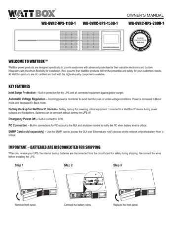
5. INSTALLATION.Read and respect the Safety Information, describedin Chapter 2 of this document. Failure to obey someof the instructions described in this manual can result in aserious or very serious accident to persons in direct contactor in the vicinity, as well as faults in the device and/or loadsconnected to it. In addition to the device’s own user manual, other documents are supplied on the CD-ROM or documentation pendrive. Consult them and strictly follow the indicated procedure. Unless otherwise indicated, all actions, instructions, guidelines and notes are applicable to the devices, whether ornot they form part of a parallel system. 5.1.2. Storage. 5.1. RECEPTION OF THE DEVICE.It is dangerous to handle the device on the pallet, asit could overturn and cause serious impact injuriesto operators and/or entrapment. Pay attention to section1.2.1. of the safety instructions -EK266*08- in all mattersrelating to the handling, movement and siting of the unit. Use the most suitable means to move the UPS while it ispacked, with a pallet jack or forklift. Any handling of the device must be carried out in accordancewith the weights shown in the technical specificationsaccording to the model, indicated in Chapter ‘9. Annexes’. 5.1.1. Reception, unpacking and contents. Reception. Check that: The data on the label affixed to the packaging corresponds to that specified on the order. Once the UPS isunpacked, check the previous data with those of thedevice nameplate.If there are discrepancies, report the issue as soon aspossible, citing the device’s manufacturing number anddelivery note references. It has not suffered any mishaps during transportation(packaging and impact indicator in perfect condition).Otherwise, follow the protocol indicated on the labelattached to the impact indicator, located on thepackaging. Unpacking. To check the contents, it will be necessary to removethe packaging.Complete the unpacking according to the procedure of section 5.1.3. Contents. The device itself. The user manual in CD-ROM or pen drive format. 1 communications cable. 2 cables for parallel connection, current and signal bus. 1 female connector for the connection of the externalEPO, with an insulated cable functioning as a jumperto close the circuit (inserted into its connector counterpart). Once the reception is completed, it is advisable to re-packthe UPS until it is put into service in order to protect itagainst mechanical shock, dust, dirt, etc. USER MANUALThe packaging of the device consists of a wooden pallet,cardboard or wooden box, depending on the item, expandedpolystyrene corners, polyethylene cover and strapping, allof which are recyclable materials. When the packagingrequires disposal, it must be carried out in accordance withcurrent laws.We recommend keeping the packaging for at least 1 year. The device storage shall be done in a dry, ventilated placeand protected from rain, dust, water splashes or chemicalagents. It is advisable to keep each device and battery unitin its original packaging, as it has been specifically designed to ensure maximum protection during transportationand storage.For devices that contain Pb-Ca batteries, thecharging times indicated in Tab. 2 of documentEK266*08 regarding the temperature to which they are exposed, must be respected, otherwise the warranty may beinvalidated.After this period, connect the device to the mains togetherwith the battery unit if applicable, start it according tothe instructions described in this manual and charge for12 hours.In parallel systems, it is not necessary to interconnect devices before battery charging. Each of them can be treatedindependently to charge them.Then shut down the device, disconnect it and store the UPSand batteries in their original packaging, noting the newdate for recharging the batteries.Do not store the devices where the ambient temperatureexceeds 50ºC or drops below -15ºC, as this may cause degradation of the electrical characteristics of the batteries.5.1.3. Unpacking.The packaging of the equipment consists of wooden pallet,carton or wood envelope according to cases, polystyrenefoamed corners [EPS] or polyethylene foam [EPE], polyethylene sheath and strap, all recyclable materials; so if youare going to get rid of them you must do it according to thelaws in force. We recommend storing the packaging in caseit should be used in the future. To unpack the device, follow the sequence in Figure 3 (cutthe straps of the cardboard packaging and lift it off as if itwere a cover or dismantle it with the necessary tools if it ismade of wood); remove the corners and plastic cover. Thiswill leave the UPS standing on the pallet. SLC TWIN PRO2 T UL UNINTERRUPTIBLE POWER SUPPLIES (UPS)13
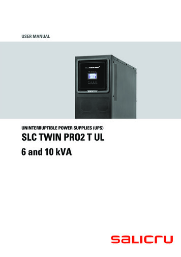
Fig. 3. Unpacking sequenceThe device is attached to the wooden pallet at the factoryby means of an L-shaped metal piece (stabilising brackets)located on each side. Remove the screws that join the piece to the pallet anddevice [see Fig. 4 and 5]. Before removing the device, withdraw the stabilisingbrackets so that they do not hinder the process andbend when impacting against the wooden ramp, which cancause damage to the structure of the device enclosure. Position the ramp as shown in Figure 3 and remove thedevice from the pallet.5.1.5. Siting, immobilising and considerations. Fig. 4.5.1.5.1. Siting for single devices. Fig. 6 shows, by way of example, typical cases dependingon the model. That which consists of a single enclosure(UPS with batteries inside) and that with the UPS with batteries in a separate enclosure or extended backup. For correct ventilation of the device, it is necessary toleave its surroundings free from obstructions. Respectthe minimum distances indicated in Tab. 1 of section1.2.1 of document EK266*08 (Safety instructions), inwhich the values for distances A, B, C and D are indicated depending on the power of each device.For the battery enclosures, maintain similar distancesto those for the UPS that makes up the system. It is recommended to leave an additional 75 cm free onthe sides to enable maintenance and repair interventions (T.S.S.) or the necessary clearance of the connection cables to facilitate the forward movement of thedevice.For extended backups with more than one enclosure, it isrecommended to place one on each side of the device and,in the case of a greater number of battery enclosures, repeat the same sequence.Fig. 5.5.1.4. Transport to the site. 14All devices have four wheels (with mechanical locking), soit is easy to move it to the installation site once unpacked.If the reception area is far from the installation site, however, it is recommended to transport the UPS by means of apallet jack or the most appropriate method considering thedistance between the two points.If the distance is considerable, it is recommended to transport the device in its packaging to the installation site andthen unpack it.SALICRU
BBUPS cabinetwithbatteriesADBAADUPS batterycabinetNo. 1UPS batterycabinetUPS cabinetAAAUPS batterycabinetNo. 2UPS cabinetADAAFig. 6. Minimum peripheral distances for UPS ventilation.BUPS batterycabinetNo. 1ADUPS batterycabinetNo. 2AUPS cabinetNo. 1AUPS cabinetNo. 2Ax2UPS batterycabinetNo. 3UPS cabinetNo. 3Ax2AAFig. 7. Minimum peripheral dis
MANUAL BYPASS SWITCH (MAINTENANCE). 6.3.1. Transfer to maintenance bypass. 6.3.2. Transfer to normal operation. 6.4. OPERATING PROCEDURE FOR A PARALLEL SYSTEM. 6.5. HOW TO INTEGRATE A NEW UPS INTO AN OPERATIONAL PARALLEL SYSTEM, OR A UPS IN SINGLE MODE. 6.6. HOW TO REPLACE A FAULTY UPS IN AN OPERATIONAL PARALLEL SYSTEM.