Transcription
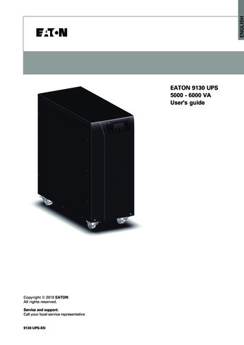
ENGLISHEATON 9130 UPS5000 - 6000 VAUser's guideCopyright 2010 EATONAll rights reserved.Service and support:Call your local service representative9130 UPS-EN
Class A EMC StatementsDirectives referencesThis UPS is classified in the C2 category according to:EMC:IEC 62040-2 Ed2: 2005Safety:IEC 62040-1: 2008 (IEC 60950-1)Performance: IEC 62040-3: 1999For immunity and safety tests, see Table 22 p. 33.Emission testing level as C2 (class A) category according to CISPR 22 Ed5.2:2006 (EN 55022).WARNING: in a residential environment, this product may cause radio interference in which case theuser may be required to take additional measures.Requesting a Declaration of ConformityUnits that are labeled with a CE mark comply with the following harmonized standards and EUdirectives:l Harmonized Standards: IEC 61000-3-12l EU Directives: 2006/95/EC, Council Directive on equipment designed for use within certainvoltage limits2004/108/EC, Council Directive relating to electromagnetic compatibilityThe EC Declaration of Conformity is available upon request for products with a CE mark.For copies of the EC Declaration of Conformity, contact Eaton Power Quality or check Eaton website:www.powerquality.eaton.comSpecial SymbolsThe following are examples of symbols used on the UPS or accessories to alert you to importantinformation:RISK OF ELECTRIC SHOCK - Observe the warning associated with the risk of electric shock symbol.CAUTION: REFER TO OPERATOR’S MANUAL - Refer to your operator’s manual for additionalinformation, such as important operating and maintenance instructions.Do not discard the UPS or the UPS batteries in the trash.This product contains sealed lead acid batteries and must be disposed as it's explain in this manual.For more information, contact your local recycling/reuse or hazardous waste center.This symbol indicates that you should not discard waste electrical or electronic equipment (WEEE) inthe trash. For proper disposal, contact your local recycling/reuse or hazardous waste center.Information, advice, help.Page 29130 UPS-EN
1. Introduction2. Installation2.12.22.32.42.52.62.72.8Inspecting the Equipment .5Unpacking the Cabinet .5Checking the Accessory Kit.6Product Installation .6Connecting the internal battery .7Connecting the EBM(s) .8Installation requirements .8Installation depending on the system earthing arrangement (SEA) .93. Power cables connection & Startup3.13.23.33.43.5Access to terminal block .11Common input sources connection .11Separate input sources connection .12Frequency converter connection .12UPS Initial Startup .134. Operation4.14.24.34.44.54.64.74.8Control Panel Functions .14Operating Modes.17UPS Startup and Shutdown.18Transferring the UPS Between Modes .19Retrieving the Event Log .19Setting Power Strategy .19Configuring Bypass Settings .19Configuring Battery Settings .205. Communication5.1 Installing Communication Options and Control Terminals .215.2 Communication Options .215.3 Eaton Power Management Software Suite .256. UPS Maintenance6.16.26.36.46.56.6UPS and Battery Care.26Storing the UPS and Batteries .26When to Replace Batteries .26Replacing Batteries.26Testing New Batteries .29Recycling the Used Battery or UPS .307. Specifications7.1 Model Specifications .318. Troubleshooting8.1 Typical Alarms and Conditions .348.2 Silencing the Alarm .368.3 Service and Support .369130 UPS-ENPage 3ENGLISHContents
1. IntroductionThe Eaton 9130 uninterruptible power system (UPS) protects your sensitive electronic equipmentfrom the most common power problems, including power failures, power sags, power surges,brownouts, line noise, high voltage spikes, frequency variations, switching transients, and harmonicdistortion.Power outages can occur when you least expect it and power quality can be erratic. These powerproblems have the potential to corrupt critical data, destroy unsaved work sessions, and damagehardware — causing hours of lost productivity and expensive repairs.With the Eaton 9130, you can safely eliminate the effects of power disturbances and guard the integrityof your equipment. Providing outstanding performance and reliability, the Eaton 9130’s unique benefitsinclude:l True online double-conversion technology with high power density, utility frequencyindependence, and generator compatibility.l ABM technology that uses advanced battery management to increase battery service life,optimize recharge time, and provide a warning before the end of useful battery life.l Selectable High Efficiency mode of operation.l Standard communication options: one RS-232 communication port, one USB communicationport, and relay output contacts.l Optional connectivity cards with enhanced communication capabilities.l Extended runtime with up to four Extended Battery Modules (EBMs) per UPS.l Firmware that is easily upgradable without a service call.l Remote shutdown control through the Remote Power-off (RPO) port.l Backed by worldwide agency approvals.Figure 1. The Eaton 9130 Tower UPS and EBM (5000–6000 VA Models Shown).Page 49130 UPS-EN
This section explains:l Equipment inspectionl Unpacking the cabinetl Checking the Accessory Kitl Product installationl Connecting the internal batteryl Connecting the EBM(s)l Installation requirements2.1Inspecting the EquipmentIf any equipment has been damaged during shipment, keep the shipping cartons and packing materialsfor the carrier or place of purchase and file a claim for shipping damage. If you discover damage afteracceptance, file a claim for concealed damage.To file a claim for shipping damage or concealed damage:1) File with the carrier within 15 days of receipt of the equipment;2) Send a copy of the damage claim within 15 days to your service representative.Check the battery recharge date on the shipping carton label. If the date has passed and thebatteries were never recharged, do not use the UPS. Contact your service representative.2.2Unpacking the Cabinetl Unpacking the cabinet in a low-temperature environment may cause condensation to occurin and on the cabinet. Do not install the cabinet until the inside and outside of the cabinet areabsolutely dry (hazard of electric shock).l The cabinet is heavy (see page 31). Use caution to unpack and move the cabinet.Unpack the equipment and remove all the packing materials and shipping cartoon (see figure 2 forunpacking 5000 & 6000 VA UPS and External battery cabinets).Note! Do not lift the UPS or External Battery Cabinets from the front panel.Figure 2. Unpacking 5000/6000 VA UPS and external battery cabinet.Discard or recycle the packaging in a responsible manner, or store it for future use.Place the cabinet in a protected area that has adequate airflow and is free of humidity, flammable gas,and corrosion.9130 UPS-ENPage 5ENGLISH2. Installation
2. Installation2.3Checking the Accessory KitVerify that the following additional items are included with the UPS:l UPS user’s guidel Software Suite CDl USB cableENGLISHl RS232 cableCopyright 2009 EATONAll rights reserved.EATON8609 6 Forks RoadRaleigh, NC 27615 U.S.A.Toll Free: 1.800.356.5794 or 919.872.3020Service and support:United States:1-800-843-9433 or 1-919-870-3028Canada:1-800-461-9166 ext 260All other countries: Call your local service comEATON 9130 UPS5000 - 6000 VAUser's guide9130 UPS-ENFigure 3. UPS Accessory kit.If you ordered an optional Extended Battery Module (EBM), verify that the following additional item isincluded with the EBM:l EBM user’s guidel Power cableFigure 4. EBM Accessory kit.Discard the EBM user’s guide if you are installing the EBM with a new UPS at the same time.Use the UPS user’s guide to install both the UPS and the EBM.2.4Product InstallationThe cabinet is heavy (see page 31). Removing the cabinet from its carton requires a minimumof two people.To1.2.3.Page 6install the cabinet:Place the UPS on a flat, stable surface in its final location.Always keep 150mm of free space behind the UPS rear panel.If installing additional cabinets, place them next to the UPS in their final location.9130 UPS-EN
2.5Connecting the internal batteryDo not make unauthorized changes to the UPS; otherwise, damage may occur to yourequipment and void your warranty.Do not connect the UPS to utility until installation is completed.To install the UPS:1. Remove the UPS front cover (see figure 5).To remove the cover:Remove the 2 fixing screws on the bottom of the cover.Push upon the bottom of the cover and pull the cover toward you to unclip it from the cabinet.A ribbon cable connects the LCD control panel to the UPS. Do not pull on the cable ordisconnect it.Figure 5. Removing the UPS front cover.A small amount of arcing may occur when connecting the internal batteries. This is normal andwill not harm personnel. Connect the cables quickly and firmly.2. Connect the internal battery connector (see figure 6).Connect the black connectors together.Press the two parts tightly together to ensure a proper connection.Figure 6. Connecting the UPS internal batteries.3. Replace the UPS front cover.To replace the cover, verify that the ribbon cable is protected, then insert the clips on the back ofthe cover into the cabinet and push firmly to snap the cover into place.Put back the 2 fixing screws on the bottom of the front.4. If you are installing power management software, connect your computer to one of thecommunication ports or optional connectivity card (see page 21). For the communication ports, usean appropriate cable (not supplied).5. If an remote power-off (disconnect) switch is required by local codes, see "Remote Power-off" (RPO)on page 22 to install the RPO switch before powering on the UPS.6. If you are installing EBM(s), continue to the following section, "Connecting the EBM(s)". Otherwise,continue to "Installation requirements" on page 8.9130 UPS-ENPage 7ENGLISH2. Installation
2. Installation2.6Connecting the EBM(s)To install the optional EBM(s) for a UPS:A small amount of arcing may occur when connecting an EBM to the UPS. This is normaland will not harm personnel. Insert the EBM cable into the UPS battery connector quickly andfirmly.1. Plug the EBM cable(s) into the battery connector(s) as shown in figure 7. Up to four EBMs may beconnected to the UPS.2. Verify that the EBM connections are tight and that adequate bend radius and strain relief exist foreach cable.3. When using external battery cabinets, the number of EBMs should be set throw the LCD panel in the"Battery settings" section, see "Configuring battery settings" on page 20.4. Continue to "Installation requirements" on page 8.Figure 7. Connecting the EBMs.2.7Installation requirementsRequired protective devices and cable cross-sections1. Recommended upstream protection (see figure 8)Table 1. Upstream circuit breaker ratingUPS power ratingUpstream circuit breaker5000 VA / 6000 VAD curve – 40 A2 poles circuit breakerLNGNTo UPS input sourceand/or Bypass source.LFigure 8. Upstream protection.Page 89130 UPS-EN
2. Requi
Page 4 9130 UPS-EN 1. Introduction The Eaton 9130 uninterruptible power system (UPS) protects your sensitive electronic equipment from the most common power problems, including power failures, power sags, power surges, brownouts, line noise, high voltage spikes, frequency variations, switching transients, and harmonic distortion.