Transcription
Integrated Flywheel Based Uninterruptible Power Supply (UPS)System for Broadcast ApplicationsWhite Paper1102128 W. Braker Lane, BK12Austin, Texas 78758-4028w w w. a c t i v e p o w e r. c o m
ObjectiveThis paper will review television transmitters, their sensitivity to certain power disturbancesand the application of integrated flywheel UPS systems on the front end to provide appropriateprotection to broadcasting equipment.2
Severe Step Load of TV TransmittersTelevision transmitters are highly sensitive to voltage variations for a number of reasons. Forexample, incoming electric power disturbances can easily take a transmitter off the air, resultingin stranded viewers and potential loss in commercial revenue. Power outages can also causesome transmitters to undergo a hard shutdown, which can damage transmitter componentsdue to the sudden loss in cooling or other control malfunctions.Figure 1: Broadcast AntennaFortunately, UPS systems can provide power conditioning and voltage regulation to ensureconstant quality power to transmitters and the necessary ride-through power to a standbygenerator for protection from extended outages. An integrated flywheel based UPS systemlike that of the CleanSource UPS system from Active Power is proven to protect broadcastcompanies from costly downtime and to guard transmitters from possible damage due to utilityevents. The architecture of the flywheel system handles overloads and step loads better thanconventional double conversion UPS systems with batteries, in part because it is designed toefficiently manage a “crowbar event” – a protective shutdown process that is built into manytransmitters.3
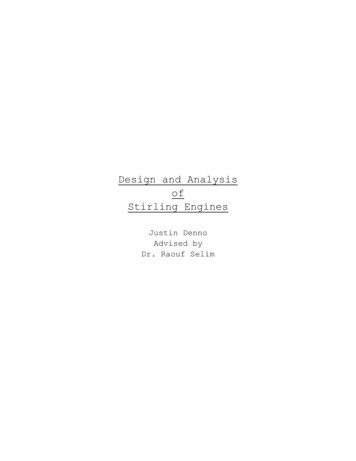
Flywheel TechnologyActive Power produces the integrated UPS and DC power system with flywheel technologythat serves as an alternative to chemical batteries. The flywheel energy storage system storeskinetic energy by spinning a compact rotor in a low-friction environment. When short-termbackup power is required due to fluctuations in utility power or power is lost, the rotor’s kineticenergy is converted to electricity.Figure 2: Flywheel AssemblyCleanSource integrates the function of a motor, flywheel rotor and generator into a singlesystem. The motor, which uses electric current from the utility grid to provide energy to rotatethe flywheel, spins at a constant speed to maintain a store of kinetic energy. The generatorconverts the kinetic energy of the flywheel into electricity as required. Refer to white paper#108 “Operation and Performance of a Flywheel-Based UPS System” for further information.The flywheel rotor is supported by Active Power’s magnetic bearing technology. This technologyunloads a majority of the flywheel’s weight from the field-replaceable mechanical bearingcartridge. A vacuum pump evacuates the chamber, reducing the drag on the spinning flywheel.The flywheel’s speed decreases as power is transferred to the load. Regulated current issupplied to the field coils to maintain constant voltage output throughout the discharge. Theflywheel based system provide ride-through power for a majority of power disturbances, suchas voltage sags and surges and bridges the gap between a power outage and the time requiredto switch to generator power.4
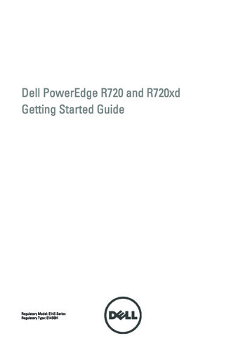
Figure 3: CleanSource UPS 300 SeriesWhat is a “Crowbar” Event?A crowbar event is the automatic shutdown method used in a high power transmitter as a safetycircuit to protect the transmitter amplifier tube or the inductive output tube (IOT) in the event ofan arc-over inside the IOT. The function of the crowbar is to remove the high voltage from theamplifier as quickly as possible, typically within a few microseconds of the detected problem.The crowbar circuit shorts out the high voltage DC power supply to the IOT for a brief periodof time, often in the range of several milliseconds. This function is typically performed with adevice called a thyratron, which is a gas-filled tube that is similar in construction to a vacuumtube. The thyratron is connected directly across the high voltage DC supply. It is a very fast,high-voltage switch, comparable to a silicon-controlled rectifier, but with much higher voltageratings and speed. When a problem is detected in the amplifier, the crowbar acts quickly;otherwise, the IOT would be destroyed, resulting in significant capital expense.The crowbar action produces a current of several thousand amps on the AC input of the highvoltage supply and on the output of the UPS supplying the transmitter. The event is equivalentto a short circuit applied directly to the output of the UPS system, which can draw up to 20 timesrated current. Assuming the input power supply to the transmitter can supply the large currentthat is demanded, the action of the crowbar does no harm to the transmitting equipment andafter a few seconds the high voltage supply returns to normal.In the event of an overload from a crowbar event, the flywheel based UPS system switches tobypass in order to help supply the desired current from the lowest impedance source and doesso without disturbing the operation of other transmitters on the same circuit.5
Putting the Flywheel UPS System to the Crowbar TestA television network with a potential audience of more than 15 million viewers has severalflywheel UPS systems deployed at different transmitter sites throughout the southeasternUnited States. At a site near Tampa, Fla., crowbar testing was performed on the output of oneof its flywheel UPS systems. This transmission site has a primary 60 kW analog transmitter witha backup 30 kW transmitter that shares the output of the UPS system with a new 65 kW digitaltransmitter equipped with a crowbar circuit.The UPS system was tested several times in order to view the response of the system duringa crowbar event of the digital transmitter. The current delivered by the UPS system during thecrowbar test peaked at 3,000 to 4,000 amps, which varied due to the position of the voltagesine wave when the crowbar fired. In one of the crowbar tests, the UPS system only dischargedfor a short period and did not have to go to bypass. In five of the six crowbar tests, the UPSsystem went to bypass via the static bypass switch and displayed a warning message due tothe severe step load. The UPS system then returned to normal on-line operation within a fewseconds. The UPS system is configured so that if the same warning message occurs morethan once per hour, the UPS system will remain in bypass mode and will require an operator toreset it. An external contact signal from a delay relay may also be used to automatically returnthe UPS to on-line operation if multiple crowbar events are expected within one hour.The other transmitter at the network’s site, which was connected to the output of the UPSsystem, stayed on the air without a glitch during all of the crowbar tests. This is partly becausethe UPS static bypass switch allows transfer to the bypass source without affecting downstreamequipment; otherwise, the critical loads could be subject to power disturbances during theevent.CONCLUSIONThe crowbar test at the transmitter site indicates the flywheel based UPS system performedexceptionally well under extreme conditions and delivers stable, uninterrupted power tosensitive loads even during severe transient conditions.6 TM2008 Active Power, Inc. All rights reserved.WP-119
Integrated Flywheel Based Uninterruptible Power Supply (UPS) System for Broadcast Applications. White Paper . 110. 2128 W. Braker Lane, BK12 Austin, Texas 78758-4028. www.activepower.com. 2. Objective. This paper will review television transmitters, their sensitivity to certain power disturbances