Transcription
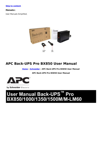
User Manual Back-UPS ProBN 1100/1350/1375/1400/1500 M2BN 1100/1350/1500 M2-CASafety and General InformationInspect the package contents upon receipt. Notify the carrier anddealer if there is any damage.SAVE THESE INSTRUCTIONS - This section contains importantinstructions that should be followed during installation and maintenanceof the UPS and batteries.DANGERHAZARD OF ELECTRIC SHOCK, EXPLOSION, OR ARC FLASH This UPS is intended for indoor use only.Do not operate this UPS in direct sunlight, in contact with fluids, or where there is excessivedust or humidity.Be sure the air vents on the UPS are not blocked. Allow adequate space for proper ventilation.Failure to follow these instructions will result in death or serious injury.CAUTIONRISK OF HYDROGEN SULPHIDE GAS AND EXCESSIVE SMOKE Connect the UPS power cable directly to a wall outlet.Battery must be replaced when they reach end of service life.Batteries must be replaced when the unit indicates battery replacement is necessary.When replacing batteries, replace with the same number and type of batteries originallyinstalled in the unit.Failure to follow these instructions could result in minor or moderate injury andequipment damage.Inventorybu476aCoaxial cableUSB communication cable
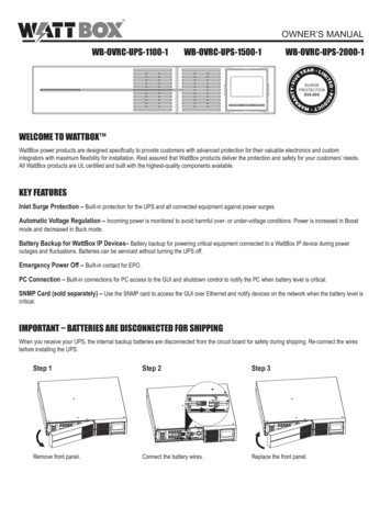
Connect the Batterybu471aThe UPS is shipped with the battery disconnected.bu472abu474abu473a Lay the UPS with the battery door facing Press the tabs downwards and pull theup. The arrows point to the locking tabs of the battery door away from the unit to accessbattery compartment.the battery modules. Using the handles on both sides of the Push the battery into the unit.battery, lift the battery 30 degrees upward toexpose the battery connector. Connect the redwire as shown above.bu475a Replace the battery door.Install PowerChute Personal Edition SoftwareUse PowerChute Personal Edition software to configure the UPS settings. During apower outage, PowerChute will save any open files on your computer and shut it down.When power is restored, it will restart the computer.Note: PowerChute is only compatible with a Windows operating system. If you areusing Mac OSX, use the native shutdown feature to protect your system. See thedocumentation provided with your computer.InstallationUse the USB communication cable supplied with the Back-UPS to connect the data porton the Back-UPS to the USB port on your computer. On the computer, go towww.apc.com Search for “PowerChute Personal Edition” then click on “View Details”to download the latest version of PCPE software. Click the download link and selectSoftware product. Select the appropriate operating system. Follow directions todownload the software.2Back-UPS Pro BN 1100/1350/1375/1400/1500 M2 / M2-CA
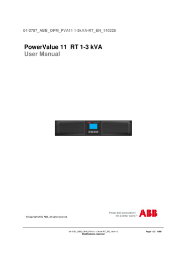
Connect the EquipmentBattery Backup and Surge Protected outletsWhen the Back-UPS is receiving input power, the Battery Backup with Surge Protectionoutlets will supply power to connected equipment. During a power outage or other ACproblems, the Battery Backup outlets receive power for a limited time from the BackUPS.Connect equipment such as printers, fax machines, scanners, or other peripherals that donot need battery backup power to the Surge Protection Only outlets. These outletsprovide full-time protection from surges even if the Back-UPS is switched OFF.e USB and Serial To use PowerChuteData port Personal Edition, connectthe supplied USBcommunication cable oran optional serial cable(not supplied).Ground screw Connect the ground leadfrom an additional surgesuppression device suchas a stand-alone data linesurge protector.BuildingIf this indicator isWiring Faultilluminated, there is aindicatorproblem with the wiringin the building. Contactan electricianimmediately and do notuse the Back-UPS.Connect a cable modemCoaxial portsor other equipment withwith surgecoaxial jacks.protectionCircuit Breaker Use to reset the systemafter an overloadcondition has occurredcausing the circuitbreaker to trip. Surge Protected These outlets provide full-time protection from surges, even if theoutletsBack-UPS is off. Connect equipment such as printers andscanners that do not require battery backup protection. In/Out Ethernet Use an Ethernet cable to connect a cable modem to the IN port,surge-protectedports Battery Backupoutlets withSurgeProtectionand connect a computer to the OUT port.During a power outage or other AC problems, the Battery Backupoutlets receive power for a limited time from the Back-UPS.Connect critical equipment such as desktop computer, computermonitor, modem or other data sensitive devices into these outlets.Back-UPS Pro BN 1100/1350/1375/1400/1500 M2 / M2-CA3
OperationPower Saving DisplayThe display interface can be configured to be continuously illuminated, or to saveenergy, it can be configured to darken after a period of inactivity.1. Full Time Mode: Press and hold DISPLAY for two seconds. The display willilluminate and the Back-UPS will beep to confirm the Full Time mode.2. Power Saving Mode: Press and hold DISPLAY for two seconds. The display willdarken and the Back-UPS will beep to confirm the Power Saving mode. While inPower Saving Mode, the display will illuminate if a button is pressed, it thendarkens after 60 seconds of no activity.Unit sensitivityAdjust the sensitivity of the Back-UPS to control when it will switch to battery power;the higher the sensitivity, the more often the Back-UPS will switch to battery power.1. Ensure the Back-UPS is connected to AC power, but is OFF.2. Press and hold the POWER button for six seconds. The LOAD CAPACITY bar willflash on and off, indicating that the Back-UPS is in programming mode.3. Press POWER again to rotate through the menu options. Stop at selectedsensitivity. The Back-UPS will beep to confirm the selection.Generator SensitivityDefaultLow sensitivity78-142 VacMedium sensitivity (Default) High sensitivity88-139 Vac88-136 VacInput voltage is extremely low The Back-UPS frequentlyor high. (Not recommended for switches to battery power.computer loads.)4Sensitive LoadsThe connected equipment issensitive to voltagefluctuations.Back-UPS Pro BN 1100/1350/1375/1400/1500 M2 / M2-CA
Front Panel Buttons and Display InterfaceUse the three buttons on the front panel of the Back-UPS and the display interface toconfigure the Back-UPS.Front panel Display button Power On/Off button Mute button Display interface USB charging ports:The 2 USB portsprovide a total of 15Wof DC power, and willprovide power evenwhen the UPS is onbattery.BN1375M2 andBN1400M2 onlyTotal of 12WDC powerOn Line: The Back-UPS is supplying conditioned AC power to connectedequipmentLoad Capacity: The load is indicated by the number of sections illuminated,one to five. Each bar represents 20% of the load.Battery Capacity: The battery charge level is indicated by the number ofblocks illuminated. When all five blocks are illuminated, the Back-UPS is atfull charge.Low Battery: When battery capacity reaches the empty level, the Back-UPSis nearing shutdown and the indicator will flash accompanied by a continuousbeep.Replace Battery: The battery is nearing the end of its useful life. When thedisplay shows a flashing Replace Battery icon and an empty Battery Capacityicon, replace the battery as early as possible.On Battery: The Back-UPS is supplying battery backup power to theconnected equipment, it will beep four times every 30 seconds.Event: The event counter shows the number of events that occurred thatcaused the Back-UPS to switch to on-battery operation.System Error Detected: The system has an error. The error number willilluminate on the display interface. See “System Errors” on page 7.Overload: The power demand from the load has exceeded the capacity of theBack-UPS.Back-UPS Pro BN 1100/1350/1375/1400/1500 M2 / M2-CA5
Mute: If the line through the speaker icon is illuminated, the audible alarmhas been turned off.Out: Output voltage, frequencyIn: Input voltage.Automatic Voltage Regulation:When illuminated, the Back-UPS is compensating for low inputvoltageEstimated Run Time: This indicates the battery runtime minutes that remainif the Back-UPS switches to battery power.Load: The total load in watts (W) or percentage(%) used by the devicesconnected to the Battery Backup outlets.Alarms and System ErrorsAudible IndicatorsFour Beeps Every 30 SecondsContinuous BeepingContinuous toneChirps every 2 SecondsContinuous chirpingBack-UPS is running on battery. You should consider savingany work in progress.Low battery condition and battery run-time is very low.Promptly save any work in progress, exit all openapplications, and shut down the operating system.Battery Backup outputs are overloaded.Battery is disconnected.Battery did not pass the automatic diagnostic test and shouldbe replaced as early as possible. Pressing the MUTE buttonpauses the chirping.Status IconsIf these icons are flashing.This may be the problem.The Back-UPS is overloaded. Disconnect one of the items connected tothe Back-UPS. If the Overload icon stops flashing, the Back-UPS is nolonger overloaded and will continue to operate normally.The Back-UPS is operating on AC power, but the battery is notfunctioning properly. Contact Schneider Electric IT (SEIT) CustomerService to order a replacement battery. See “Replacement Battery” onpage 10.The Back-UPS is operating on battery power and the battery power isgetting low. Shut down all connected equipment to avoid losing anunsaved data. When possible, connect the Back-UPS to AC power torecharge the battery.The battery is not connected. See “Connect the Battery” on page 2 tomake sure battery wires are connected properly.6Back-UPS Pro BN 1100/1350/1375/1400/1500 M2 / M2-CA
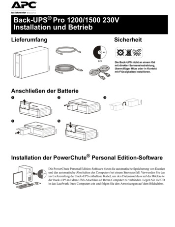
System ErrorsThe Back-UPS will display these error messages. Except for errors F01 and F02, contactSEIT Technical Support.F01bu088dF02F04F05F06F07F09Turn the Back-UPS off.Disconnect non-essentialOn-Battery Overload equipment from the BatteryBackup outlets and the turnBack-UPS on.Turn the Back-UPS off.Disconnect all equipment fromthe Battery Backup outlets andOn-Battery Output the turn Back-UPS on.ShortRe-connect equipment one itemat a time. If the output is trippedagain, disconnect the device thatcaused the error.Clamp ShortErrors F04-F09 cannot beCharge Errorcorrected by the user, contactRelay WeldingSEIT Technical Support forTemperatureassistance.Internal ErrorBack-UPS Pro BN 1100/1350/1375/1400/1500 M2 / M2-CA7
Function Button Quick ReferenceTiming(seconds)UPSStatusPower On0.2OffPower Off2On0.2OnVerify the status or condition of the Back-UPS. TheLCD will illuminate for 60 seconds. Press the buttonthe toggle into various information.2OnThe LCD will illuminate and the Back-UPS will beepto confirm the Full-Time mode. The LCD will darkenand the Back-UPS will beep to confirm the PowerSaving mode. While in Power-Saving Mode, the LCDwill illuminate if a button is pressed, then darkens after60 seconds of no activity.2OnFunctionButtonDescriptionPowerPress POWER to start receiving input AC power. If ACinput power is not available, the Back-UPS will run onbattery power.The Back-UPS is not receiving input AC power, but isproviding surge ngmodeMuteEnable/DisablemodeEnable or disable the audible alarms. The Mute iconwill illuminate and the Back-UPS will beep one time.Sensitivity6OffThe Load Capacity icon will blink, indicating that theBack-UPS is in programming mode. Use the POWERbutton to scroll through Low, Medium, and High, stopat selected sensitivity. The Back-UPS will beep toconfirm selection. See "Unit sensitivity" for details.Self-Test(manual)6OnThe Back-UPS will perform a test of the internalbattery. Note: This will happen automatically when theBack-UPS is turned ON or when the Back-UPSpreviously detected a bad battery.EventReset0.2OnWhen the Event screen is visible, press and holdDISPLAY, then press POWER, to clear the detected errorevent counter.ErrorReset2Error8After an error has been identified, press POWER toremove the visual indication and return to standbystatus.Back-UPS Pro BN 1100/1350/1375/1400/1500 M2 / M2-CA
TroubleshootingProblemPossible CauseCorrective ActionThe Back-UPS is not connected to AC Ensure that the Back-UPS is securelypower.connected to an AC outlet.The circuit breaker has been tripped.Back-UPS will notswitch on.Disconnect non-essential equipmentfrom the Back-UPS. Reset the circuitbreaker. Re-connect equipment oneitem at a time. If the circuit breaker istripped again, disconnect the device thatcaused the trip.The internal battery is not connected. Connect the battery.The AC input voltage is out of range. Adjust the transfer voltage andsensitivity range.The Back-UPS does Ensure that essential equipment is not Disconnect equipment from the SURGEONLY outlet and re-connect to a Batterynot provide power plugged into a SURGE ONLY outlet.Backup outlet.during a AC poweroutage.The plug has partially pulled out ofthe wall outlet, the wall outlet is nolonger receiving AC power, or thecircuit breaker has been tripped.Ensure that the plug is fully insertedinto the wall outlet. Ensure that the walloutlet is receiving AC power bychecking it with another device.Battery Backup outlets may be fullyor improperly loaded.Disconnect non-essential equipmentfrom the Battery Backup outlets andconnect the equipment to SURGEoutlets.The Back-UPS isoperating on batterypower, whileThe Back-UPS is performing anNo action is necessary.connected to ACautomatic self test.power.The AC input voltage is out of range, Adjust the transfer voltage andthe frequency is out of range, or the sensitivity range.waveform is distorted.The Back-UPS doesnot provide theThe battery was recently dischargedexpected amount ofdue to a power outage and has notbackup time.fully recharged.Charge the battery cartridge for 16hours.The battery has reached the end of its Replace the battery.useful life.The battery has reached the end of its Replace the battery as early as possible.The REPLACEBATTERY indicator is useful life.illuminated.The OVERLOADindicator isilluminated.The SYSTEM ERRORindicator isilluminated, all thefront panelindicators areflashing.The equipment connected to theBack-UPS is drawing more powerthan the Back-UPS can provide.Disconnect non-essential equipmentfrom the Battery Backup outlets andconnect the equipment to SURGEoutlets.There is an internal error.Determine which internal errormessage is displayed by matching thenumber displayed on the LCD with thecorresponding Error Message (see"System Errors") and contact SEITTechnical Support.Back-UPS Pro BN 1100/1350/1375/1400/1500 M2 / M2-CA9
SpecificationsBN1100M2BN1350M2BN1375M2BN1100M2-CA BN1350M2-CAVA1100 VAMaximum Load1350 VA600WBN1400M21375 VABN1500M2BN1500M2-CA1400 VA1500 VA810W900WNominal InputVoltageOnline InputVoltage RangeAutomatic VoltageRegulationBoost by 11.3% when input voltage drops below limitFrequency Range60 Hz 3 HzOn-batteryWaveshapeUSB chargingportTypical RechargeTime1100, 1350, 1500 VA models: Type C*1, Type A*1 (15W in total)1375 and 1400 VA models: Type A*2 (12W in total)120 V88 - 139 VStep-approximated sine-wave16 hoursTransfer Time8 ms, maximumOperatingTemperatureStorageTemperature32 to 104 oF (0 40 oC)23 to 113 oF (-15 40 oC)Unit DimensionsUnit Weight11.9 4.4 15.0 in (368 100 260 mm)21.6 lb (9.8 kg)Interface22.9 lb (10.4 kg)25.1 lb (11.4 kg)USB and Simple SignalOn-BatteryRuntimeGo to http://www.apc.com/productReplacement BatteryThe battery typically lasts for 3 to 5 years, a shorter period if subjected to frequentoutages or elevated temperatures. Battery replacement parts for Back-UPS ProBN1100M2 is APCRBC160, for BN1350M2, BN1375M2 and BN1400M2 isAPCRBC162, and for BN1500M2 is APCRBC161. Delaying the replacement of partsmay corrode the batteries in the cartridge. Recycle spent battery cartridges.WarrantyThe standard warranty is three (3) years from the date of purchase. Schneider Electric IT(SEIT) standard procedure is to replace the original unit with a factory reconditionedunit. Customers who must have the original unit back due to the assignment of asset tagsand set depreciation schedules must declare such a need at first contact with an SEITTechnical Support representative. SEIT will ship the replacement unit once the defectiveunit has been received by the repair department, or cross ship upon the receipt of a validcredit card number. The customer pays for shipping the unit to SEIT. SEIT pays groundfreight transportation costs to ship the replacement unit to the customer.10Back-UPS Pro BN 1100/1350/1375/1400/1500 M2 / M2-CA
APC by Schneider Electric IT Customer SupportWorldwideFor country specific customer support, go to the APC by Schneider Electric Web site,www.apc.com.Select models are ENERGY STAR qualified.For more information on your specific model go to www.apc.com.This UPS is certified to comply with California Battery Charger Systemregulations. For more information go MC ComplianceThis equipment has been tested and found to comply with the limits for a Class B digitaldevice, pursuant to part 15 of the FCC Rules. These limits are designed to providereasonable protection against harmful interference in a residential installation. Thisequipment generates, uses and can radiate radio frequency energy and, if not installedand used in accordance with the instructions, may cause harmful interference to radiocommunications. However, there is no guarantee that interference will not occur in aparticular installation. If this equipment does cause harmful interference to radio ortelevision reception, which can be determined by turning the equipment off and on, theuser is encouraged to try to correct the interference by one or more of the followingmeasures: Reorient or relocate the receiving antenna. Increase the separation between the equipment and receiver. Connect the equipment into an outlet on a circuit different from that to which thereceiver is connected. Consult the dealer or an experienced radio/TV technician for help.Back-UPS Pro BN 1100/1350/1375/1400/1500 M2 / M2-CA11
2017 APC by Schneider Electric. APC, the APC logo, and Back-UPS are ownedby Schneider Electric Industries S.A.S. or their affiliated companies. All othertrademarks are property of their respective owners.EN 990-9100206/2017
8 Back-UPS Pro BN 1100/1350/1375/1400/1500 M2 / M2-CA Function Button Quick Reference Function Button Timing (seconds) UPS Status Description Power Power On 0.2 Off Press POWER to start receiving input AC power. If AC input power is not available, the Back-UPS will run on battery power. Power Off 2On The Back-UPS is not receiving input AC power .