Transcription
MIPI CSI-2 TransmitSubsystem v1.0Product GuideVivado Design SuitePG260 June 7, 2017
Table of ContentsIP FactsChapter 1: OverviewSub-Core Details. . . . . . . . . . . . . . . . . . . . . . . . . . . . . . . . . . . . . . . . . . . . . . . . . . . . . . . . . . . . . . . . . . .Applications . . . . . . . . . . . . . . . . . . . . . . . . . . . . . . . . . . . . . . . . . . . . . . . . . . . . . . . . . . . . . . . . . . . . . .Unsupported Features. . . . . . . . . . . . . . . . . . . . . . . . . . . . . . . . . . . . . . . . . . . . . . . . . . . . . . . . . . . . . .Licensing and Ordering Information . . . . . . . . . . . . . . . . . . . . . . . . . . . . . . . . . . . . . . . . . . . . . . . . . . .6778Chapter 2: Product SpecificationStandards . . . . . . . . . . . . . . . . . . . . . . . . . . . . . . . . . . . . . . . . . . . . . . . . . . . . . . . . . . . . . . . . . . . . . . . . 9Resource Utilization. . . . . . . . . . . . . . . . . . . . . . . . . . . . . . . . . . . . . . . . . . . . . . . . . . . . . . . . . . . . . . . . 9Port Descriptions . . . . . . . . . . . . . . . . . . . . . . . . . . . . . . . . . . . . . . . . . . . . . . . . . . . . . . . . . . . . . . . . . . 9Pixel Encoding . . . . . . . . . . . . . . . . . . . . . . . . . . . . . . . . . . . . . . . . . . . . . . . . . . . . . . . . . . . . . . . . . . . 13Register Space . . . . . . . . . . . . . . . . . . . . . . . . . . . . . . . . . . . . . . . . . . . . . . . . . . . . . . . . . . . . . . . . . . . 15Chapter 3: Designing with the SubsystemGeneral Design Guidelines . . . . . . . . . . . . . . . . . . . . . . . . . . . . . . . . . . . . . . . . . . . . . . . . . . . . . . . . .Shared Logic . . . . . . . . . . . . . . . . . . . . . . . . . . . . . . . . . . . . . . . . . . . . . . . . . . . . . . . . . . . . . . . . . . . . .I/O Planning . . . . . . . . . . . . . . . . . . . . . . . . . . . . . . . . . . . . . . . . . . . . . . . . . . . . . . . . . . . . . . . . . . . . .Clocking. . . . . . . . . . . . . . . . . . . . . . . . . . . . . . . . . . . . . . . . . . . . . . . . . . . . . . . . . . . . . . . . . . . . . . . . .Resets . . . . . . . . . . . . . . . . . . . . . . . . . . . . . . . . . . . . . . . . . . . . . . . . . . . . . . . . . . . . . . . . . . . . . . . . . .Protocol Description . . . . . . . . . . . . . . . . . . . . . . . . . . . . . . . . . . . . . . . . . . . . . . . . . . . . . . . . . . . . . .222224262728Chapter 4: Design Flow StepsCustomizing and Generating the Subsystem . . . . . . . . . . . . . . . . . . . . . . . . . . . . . . . . . . . . . . . . . . .Constraining the Subsystem . . . . . . . . . . . . . . . . . . . . . . . . . . . . . . . . . . . . . . . . . . . . . . . . . . . . . . . .Simulation . . . . . . . . . . . . . . . . . . . . . . . . . . . . . . . . . . . . . . . . . . . . . . . . . . . . . . . . . . . . . . . . . . . . . .Synthesis and Implementation . . . . . . . . . . . . . . . . . . . . . . . . . . . . . . . . . . . . . . . . . . . . . . . . . . . . . .30353737Appendix A: Verification, Compliance, and InteroperabilityHardware Validation . . . . . . . . . . . . . . . . . . . . . . . . . . . . . . . . . . . . . . . . . . . . . . . . . . . . . . . . . . . . . . 38Appendix B: DebuggingFinding Help on Xilinx.com . . . . . . . . . . . . . . . . . . . . . . . . . . . . . . . . . . . . . . . . . . . . . . . . . . . . . . . . . 39MIPI CSI-2 TX Subsystem v1.0PG260 June 7, 2017www.xilinx.comSend Feedback2
Debug Tools . . . . . . . . . . . . . . . . . . . . . . . . . . . . . . . . . . . . . . . . . . . . . . . . . . . . . . . . . . . . . . . . . . . . . 40Hardware Debug . . . . . . . . . . . . . . . . . . . . . . . . . . . . . . . . . . . . . . . . . . . . . . . . . . . . . . . . . . . . . . . . . 41Interface Debug . . . . . . . . . . . . . . . . . . . . . . . . . . . . . . . . . . . . . . . . . . . . . . . . . . . . . . . . . . . . . . . . . . 41Appendix C: Additional Resources and Legal NoticesXilinx Resources . . . . . . . . . . . . . . . . . . . . . . . . . . . . . . . . . . . . . . . . . . . . . . . . . . . . . . . . . . . . . . . . . .References . . . . . . . . . . . . . . . . . . . . . . . . . . . . . . . . . . . . . . . . . . . . . . . . . . . . . . . . . . . . . . . . . . . . . .Revision History . . . . . . . . . . . . . . . . . . . . . . . . . . . . . . . . . . . . . . . . . . . . . . . . . . . . . . . . . . . . . . . . . .Please Read: Important Legal Notices . . . . . . . . . . . . . . . . . . . . . . . . . . . . . . . . . . . . . . . . . . . . . . . .MIPI CSI-2 TX Subsystem v1.0PG260 June 7, 2017www.xilinx.comSend Feedback444445453
IP FactsIntroductionIP Facts TableThe Mobile Industry Processor Interface (MIPI)Camera Serial Interface (CSI-2) TX subsystemimplements a CSI-2 transmit interfaceaccording to the MIPI CSI-2 standard, v1.1[Ref 1]. The CSI-2 TX subsystem packs theincoming pixel data to CSI-2 packets with therequired pixel to byte conversion, header andfooter insertion. Also generates the requiredframe and line marker packets. These packetsare then sent over DPHY interface fortransmission.Subsystem SpecificsSupportedDevice Family (1)UltraScale Families,Zynq UltraScale MPSoC,Zynq -7000 All Programmable SoC,Virtex -7, Kintex -7, Artix -7Supported UserInterfacesAXI4-Lite, AXI4-Stream, Native VideoPerformance and Resource Utilization webpageResourcesProvided with SubsystemDesign FilesEncrypted RTLExample DesignNot ProvidedTest BenchNot ProvidedConstraints FileFeaturesSimulationModel Support for 1 to 4 D-PHY lanesSupportedS/W Driver (2) Maximum data rate of 1.5 Gb/s Multiple data type support (RAW, RGB, YUV,User defined) Support for single, dual, quad pixel modes Support for 1 to 4 virtual channels Low power state (LPS) insertion betweenthe packetsNot ProvidedStandaloneTested Design Flows(3)Design EntrySimulationVivado Design SuiteFor supported simulators, see theXilinx Design Tools: Release Notes Guide.SynthesisVivado SynthesisSupportProvided by Xilinx at the Xilinx Support web page Ultra low power (ULP) mode generationusing register access Interrupt generation to indicate subsystemstatus information AXI4-Lite interface for register access toconfigure different subsystem options Configurable Line Start/Line End packetgeneration Configurable selection of D-PHY registerinterfaceMIPI CSI-2 TX Subsystem v1.0PG260 June 7, 2017XDCNotes:1. For a complete list of supported devices, see the Vivado IPcatalog.2. Standalone driver details can be found in the SDK directory( install directory /SDK/ release /data/embeddedsw/doc/xilinx drivers.htm). Linux OS and driver support informationis available from theXilinx Wiki page.3. For the supported versions of the tools, see theXilinx Design Tools: Release Notes Guide.www.xilinx.com4Product SpecificationSend Feedback
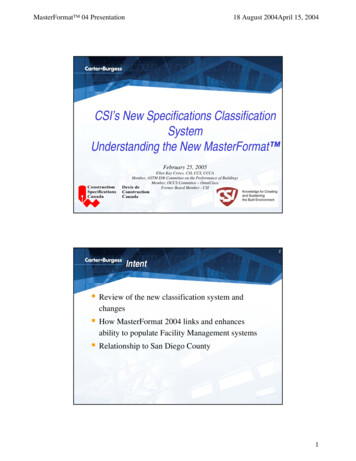
Chapter 1OverviewThe MIPI CSI-2 TX subsystem allows you to quickly create systems based on the MIPIprotocol. It interfaces between image sensors and an image sensor pipe. An internal highspeed physical layer design, D-PHY, is provided that allows direct connection to MIPI basedreceivers. The top level customization parameters select the required hardware blocksneeded to build the subsystem. Figure 1-1 shows the subsystem architecture.X-Ref Target - Figure 1-1AXI4-LiteInterfaceAXI Cross Bardphy clk 200Ms axis aclks axis aresetnNative Video / AXISInterfaceMIPI CSI2Tx/Controller PPIFigure 1-1:MIPIDPHYSerial InterfaceSubsystem ArchitectureThe subsystem consists of the following sub-cores: MIPI D-PHY MIPI CSI-2 TX Controller AXI CrossbarMIPI CSI-2 TX Subsystem v1.0PG260 June 7, 2017www.xilinx.comSend Feedback5
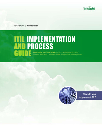
Chapter 1:OverviewSub-Core DetailsMIPI D-PHYThe MIPI D-PHY IP core implements a D-PHY TX interface and provides PHY protocol layersupport compatible with the CSI-2 TX interface. MIPI I/O bank support & I/O Planner arepresent only for UltraScale devices. For more details, refer MIPI D-PHY LogiCORE IPProduct Guide (PG202) [Ref 3].MIPI CSI-2 TX ControllerCSI provides the mobile industry a standard, robust, scalable, low-power, high-speed,cost-effective interface that supports a wide range of imaging solutions for mobile devices.MIPI CSI-2 TX Controller receives stream of image data via Native video or AXI4-Streaminput interface. The controller adds the synchronization packets and performs thepixel-to-byte conversions for the pixel data. Packed byte data is sent over the D-PHYinterface for transmission. AXI4-Lite interface is used to access core registers. The MIPICSI2-TX Controller supports ECC and CRC generation for header and payload respectively.X-Ref Target - Figure 1-2AXI4 Lite InterfaceInterruptRegister ModuleSynchronization ModuleECCNative Video / AXISInterfacelinebufferimage ifacePacketizerLaneDistributionBlockPPICRCFigure 1-2:MIPI CSI-2 TX Controller CoreFeatures of this core include: Multi-lane interoperability that allows more bandwidth than that provided by one lane.Those trying to avoid high clock rates, can expand the data path to multiple lanes andobtain approximately linear increases in peak bus bandwidth Short and long packets with all word count values supported and can be used for lowlevel protocol communicationMIPI CSI-2 TX Subsystem v1.0PG260 June 7, 2017www.xilinx.comSend Feedback6
Chapter 1:Overview Error Correction Code (ECC) for error generation in Long and Short packet header. Todetect possible errors in transmission, a checksum is calculated over each data packet.The checksum is realized as 16-bit CRC. The generator polynomial is x16 x12 x5 x0 Supports embedded non-image data transmission using the same input Native videoor AXI4S interface. Supports active lane configuration, programmable native video interface or AXI4streaming interface, and programmable CRC generation.AXI CrossbarThe AXI Crossbar core is used in the subsystem to route AXI4-Lite requests tocorresponding sub-cores based on the address. See the AXI Interconnect LogiCORE IPProduct Guide [Ref 4] for details.ApplicationsThe Xilinx MIPI CSI-2 TX controller implements camera sensor transmit interface over MIPID-PHY interface. It can be used to bridge between non-MIPI camera sensors to MIPI basedimage sensor processors or to map video data captured over other interfaces such as HDMIand DisplayPort to a MIPI CSI interface. MIPI is a group of protocols defined by the mobileindustry group to standardize all interfaces within mobile platforms such as mobile phonesand tablets. However the large volumes and the economies of scale of the mobile industryis forcing other applications to also adopt these standards. As such MIPI-based camerasensors and Image sensor processors are being increasingly used in applications such asdriver assistance technologies in automotive applications, video security surveillancecameras, video conferencing and emerging applications such as virtual and augmentedreality.Unsupported Features Secondary data types excluding RAW12,RAW14 are not supported.MIPI CSI-2 TX Subsystem v1.0PG260 June 7, 2017www.xilinx.comSend Feedback7
Chapter 1:OverviewLicensing and Ordering InformationLicense CheckersIf the IP requires a license key, the key must be verified. The Vivado design tools haveseveral license checkpoints for gating licensed IP through the flow. If the license checksucceeds, the IP can continue generation. Otherwise, generation halts with error. Licensecheckpoints are enforced by the following tools: Vivado synthesis Vivado implementation write bitstream (Tcl command)IMPORTANT: IP license level is ignored at checkpoints. The test confirms a valid license exists. It doesnot check IP license level.License TypeThis Xilinx module is provided under the terms of the Xilinx Core License Agreement. Themodule is shipped as part of the Vivado Design Suite. For full access to all corefunctionalities in simulation and in hardware, you must purchase a license for the core.Contact your local Xilinx sales representative for information about pricing and availability.For more information, visit the MIPI CSI-2 TX Subsystem product web page.Information about other Xilinx LogiCORE IP modules is available at the Xilinx IntellectualProperty page. For information on pricing and availability of other Xilinx LogiCORE IPmodules and tools, contact your local Xilinx sales representative.MIPI CSI-2 TX Subsystem v1.0PG260 June 7, 2017www.xilinx.comSend Feedback8
Chapter 2Product SpecificationStandards MIPI Alliance Standard for Camera Serial Interface CSI-2 v1.1 [Ref 1] MIPI Alliance Physical Layer Specifications, D-PHY Specification v1.1 [Ref 6] Processor Interface, AXI4-Lite: see the Vivado Design Suite: AXI Reference Guide(UG1037) [Ref 7] Input Pixel Interface: see the AXI4-Stream Video IP and System Design Guide (UG934)[Ref 2]Resource UtilizationFor full details about performance and resource utilization, visit the Performance andResource Utilization web page.Port DescriptionsThe MIPI CSI-2 TX Subsystem I/O signals are described in Table 2-1.Table 2-1:Port DescriptionsSignal nameInterfaceDirectionDescriptionDPHY Interface (7 Series family) Shared Logic in the Coretxclkesc outPPIOutputUse to connect the txclkesc pin.oserdes clk outPPIOutputUse to connect the OSERDES clock pin.Frequency of the clock is line rate/2MIPI CSI-2 TX Subsystem v1.0PG260 June 7, 2017www.xilinx.comSend Feedback9
Chapter 2:Table 2-1:Product SpecificationPort Descriptions (Cont’d)Signal puttxbyteclkhs frequency for D-PHY TXwhen the shared logic is inside the core.The frequency of the clock is line rate/8.0This clock has 90 phase shift (quadraturealignment) with oserdes clk outsystem rst outPPIOutputActive-high system resetOutput to be used by the example designlevel logicmmcm lock outPPIOutputMMCM lock indicationActive-HighPPIOutputD-PHY clock lane serial linesPPIOutputD-PHY data lane serial linesWidth of these ports is equal to the numberof lanesPPIOutputD-PHY LP clock lane serial linesPPIOutputD-PHY LP serial linesWidth of these ports is equal to the numberof lanesclk hs txpclk hs txndata hs txp[N:0]data hs txn[N:0]clk lp txpclk lp txndata lp txp[N:0]data lp txn[N:0]DPHY Interface (UltraScale ) Shared Logic in the Corexiphy byteclk outPPIOutputGoes as an input to PHYUsed to transmit high-speed dataclkoutphy outPPIOutputPHY serial clockpll lock outPPIOutputPLL lock indicationtxbyteclkhsPPIOutputtxbyteclkhs frequency for D-PHY TXwhen the shared logic is inside the coreFrequency is line rate/8.0clk txp/nPPIOutputDPHY clock lane serial linesPPIOutputDPHY data lane serial linesWidth of these ports is equal to the numberof lanesdata txp[N:0]/n[N:0]DPHY Interface (UltraScale ) Shared Logic in Example Designclk txpPPIOutputD-PHY clock lane serial linesPPIOutputD-PHY data lane serial linesWidth of these ports is equal to the numberof lanesxiphy byteclk inPPIInputConnect the xiphy byteclk pinclkoutphy inPPIInputConnect the clkoutphy pinclk txndata txp[N:0]data txn[N:0]MIPI CSI-2 TX Subsystem v1.0PG260 June 7, 2017www.xilinx.comSend Feedback10
Chapter 2:Table 2-1:Product SpecificationPort Descriptions (Cont’d)Signal nameInterfaceDirectionDescriptionpll lock inPPIInputConnect the PLL PinsActive-Hightxclkesc inPPIInputEscape clocksystem rst inPPIInputActive-High system resettxbyteclkhs inPPIInputByteclkhs for D-PHY TX when shared logicis in example designFrequency is line rate/8.0DPHY Interface (7 Series Family) Shared Logic in Example Designtxclkesc inPPIInputEscape Clockoserdes clk inPPIInputConnect the OSERDES CLK pinFrequency is line rate/2.txbyteclkhs inPPIInputFrequency for D-PHY TX when Shared Logicis in example designFrequency is line rate/8.0system rst inPPIInputActive-high system resetPPIOutputD-PHY clock lane serial linesPPIOutputD-PHY data lane serial linesWidth of these ports is equal to the numberof lanesPPIOutputD-PHY LP Clock Lane Serial LinePPIOutputD-PHY LP serial linesWidth of these ports is equal to the numberof lanesS AXI-s axis aclkSystemInputAXI clock (same clock for lite and streaminterface)s axis aresetnSystemInputAXI reset. Active-Low (same reset for liteand stream interface)s axis treadyS AXISOutputclk hs txpclk hs txndata hs txp[N:0]data hs txn[N:0]clk lp txpclk lp txndata lp txp[N:0]data lp txn[N:0]AXI4-Lite Interfaces axi *AXI4-lite interfaceAXI4-Stream Input InterfaceMIPI CSI-2 TX Subsystem v1.0PG260 June 7, 2017www.xilinx.comDriven by the CSI2 TX controllerIndicates that the controller is ready toaccept the dataSend Feedback11
Chapter 2:Table 2-1:Product SpecificationPort Descriptions (Cont’d)Signal nameInterfaceDirectionDescriptions axis tvalidS AXISInputIndicates that the data on s axis tdata isvalidWhen high, and is the first pixel of the line,it validates the following signals: s axis tdest s axis tuser[47:32] s axis tuser[63:48]s axis tlastS AXISInputIndicates the line end and is triggered onlast pixel of every lines axis tdata[N-1:0]S AXISInputAXI4-stream interfaceWidth of this port is dependent on the pixeltype and the number of pixels per beats axis tdest[1:0]S AXISInputAXI4-stream interfaceVirtual channel identifierS AXISInputAXI4-stream sideband interface 95-64 Reserved 63-48 Word count 47-32 Line number 31-16 Frame number 6-1 Data type 0 Frame startvid vsyncVideoInputActive-High vertical syncvid hsyncVideoInputActive-High horizontal syncvid enableVideoInputActive-High pixel data enables axis tuser[95:0]Native Video Interfacevid pxl[N-1:0]VideoInputVideo DataWidth of this port is dependent on pixeltype and the number of pixels per beatSampled at when vid enable is highvid vc[1:0]VideoInputVirtual Channel IdentifierSampled at the rising edges of vid vsync orvid hsync or vid enablevid di[5:0]VideoInputIndicates the Data ID of the incoming longpacketSampled on the rising edges of vid hsyncvid linenum[15:0]VideoInputLine number to useSampled at Hsync rising edgevid framenum[15:0]VideoInputFrame number to useSampled at Vsync rising edgevid wc[15:0]VideoInputWord count of the long packetSampled at Hsync rising edgeMIPI CSI-2 TX Subsystem v1.0PG260 June 7, 2017www.xilinx.comSend Feedback12
Chapter 2:Table 2-1:Product SpecificationPort Descriptions (Cont’d)Signal m InterfaceInterruptSystem interrupt outputThe core adds data ID implicitly on detection for the synchronization of short packets suchas Frame Start/End, and Line Start/End. For more details, refer Appendix B, Debugging.Table 2-2 lists the axis ports and their values when you want to drive Data Type RAW8,Horizontal Pixels 3840 on Virtual Channel (V.C) 3 on an AXI streaming interface.Table 2-2:Port Values on AXI4-Stream InterfacePortValues axis tuser[6-1]0x2As axis tuser[63-48]0x0F00s axis tdest[1:0]0x3Table 2-3 lists the native ports and their values when you want to drive Data Type RAW12,Horizontal Pixels 3840 on Virtual Channel (V.C) 2 on a native video interface.Table 2-3:Port Values on Native Video InterfacePortValuevid di[5:0]0x2Cvid wc[15:0]0x1680vid vc[1:0]0x2Pixel EncodingThis section elaborates the pixel encoding and the s axis tdata or the vid pxl portwidth generation followed by the MIPI CSI-2 TX controller. For more details, referAXI4-Stream Video IP and System Design Guide (UG934)[Ref 2].The width of the s axis tdata or the vid pxl port is calculated as shown below:Data Width Byte aligned of (14*3*Pixel Mode)MIPI CSI-2 TX Subsystem v1.0PG260 June 7, 2017www.xilinx.comSend Feedback13
Chapter 2:Product SpecificationFor example, the data width for 1 Pixel Mode is 14*3*1 resulting in 42. Therefore, the widthhas to be byte aligned with the final Data Width, which in this case is 48 ([47:0]).Table 2-4 lists the pixel encoding for single pixel per beat.Table 2-4:Pixel Encoding for Single Pixel per Beat[12DW-1: [11DW-1: [10DW-1: [9DW-1: [8DW-1: [7DW-1: [6DW-1: [5DW-1: 1:2DW][2DW-1:DW][DW-1:0][167:154] [153:140] [139:126] [125:112] [111:98] 69:56][55:42]Data 565R0[41:37]B0[27:23]G0[13:8][12DW-1: [11DW-1: [10DW-1: [9DW-1: [8DW-1: [7DW-1: [6DW-1: [5DW-1: [4DW-1: [3DW-1: W][DW-1:0]Table 2-5 lists the pixel encoding for dual pixel per beat.Table 2-5:Pixel Encoding for Dual Pixel per BeatGenericBoundary[167:154] [153:140] [139:126] [125:112] [111:98] W8, USD,Embeddednon-image [27:16]P0[13:2]RAW14P1[27:14]P0[13:0]Data ]B0[27:23]G0[13:8]Table 2-6 lists the pixel encoding for quad pixel per beat.MIPI CSI-2 TX Subsystem v1.0PG260 June 7, 2017www.xilinx.comSend Feedback14
Chapter 2:Table 2-6:Product SpecificationPixel encoding for Quad Pixel per Beat[12DW-1: [11DW-1: [10DW-1: [9DW-1: [8DW-1: [7DW-1: [6DW-1: [5DW-1: [4DW-1: [3DW-1: W]GenericBoundary[167:154] [153:140] [139:126] [125:112] [111:98] [13:0]RAW8, USD,Embeddednon-image ]P0[13:0]Data 1[55:50]R0[41:37]B0[27:23]G0[13:8]Register SpaceThis section details registers available in the MIPI CSI-2 TX Subsystem. The address map issplit into following regions: MIPI CSI-2 TX Controller core MIPI D-PHY coreEach IP core is given an address space of 32K. Example offset addresses from the systembase address when the MIPI D-PHY registers are enabled are shown in Table 2-7.Table 2-7:Sub-Core Address OffsetsMIPI CSI-2 TX Subsystem v1.0PG260 June 7, 2017IP CoresOffsetMIPI CSI-2 TX Controller0x0000MIPI D-PHY0x1000www.xilinx.comSend Feedback15
Chapter 2:Product SpecificationMIPI CSI-2 TX Controller Core RegistersTable 2-8 specifies the name, address, and description of each firmware addressableregister within the MIPI CSI-2 TX controller core.Table 2-8:MIPI CSI-2 TX Controller Core RegistersAddress OffsetRegister NameDescription0x00Core ConfigurationCore configuration options0x04Protocol ConfigurationProtocol configuration options0x08Reserved d0x1CReserved0x20Global Interrupt EnableGlobal interrupt enable registers0x24Interrupt statusInterrupt status register0x28Interrupt enableInterrupt enable register0x2CReserved0x30Generic short packet 4Reserved0x78Generic Short Packet StatusMIPI CSI-2 TX Subsystem v1.0PG260 June 7, 2017Entry for the generic short packetsGeneric short packet FIFO statuswww.xilinx.comSend Feedback16
Chapter 2:Table 2-8:MIPI CSI-2 TX Controller Core Registers (Cont’d)Address Offset0x7CProduct SpecificationRegister NameDescriptionReservedNotes:1. Access type and reset value for all the reserved bits in the registers is read-only with value 0.2. Register accesses should be word aligned and there is no support for a write strobe. WSTRB is not used internally.3. Only the lower 7 bits (6:0) of the read and write address of the AXI4-Lite interface are decoded. This means thataccessing address 0x00 and 0x80 results in reading the same address of 0x00.4. Reads and writes to addresses outside this table do not return an error.Core Configuration RegisterThe Core Configuration register is described in Table 2-9 and allows you to enable anddisable the MIPI CSI-2 TX Controller core and apply a soft reset during core operation.Table 2-9:Bits31–5Core Configuration RegisterNameReservedReset Value AccessN/ADescriptionN/AReservedNot used by the coreRecommended to write 04Clock Mode0x0R/WClock mode configuration0: Continuous clock mode1: Non-continuous clock mode3ULPS Mode0x0R/WDrives the lane into ULPS mode0: Exit1: Entry21ControllerReadySoft ResetMIPI CSI-2 TX Subsystem v1.0PG260 June 7, 20170x10x0RR/WController is ready for processingDuring soft-reset or core disable, rely on this status toensure if the core has stopped all its activity1: Controller is Ready0: Controller is InactiveSoft reset to core1: Resets the ISR bits only0: Takes the core out of soft resetOnce the soft reset is released, core starts capturingnew status information to ISRwww.xilinx.comSend Feedback17
Chapter 2:Table 2-9:Product SpecificationCore Configuration Register (Cont’d)BitsName0Reset Value AccessCore Enable0x0R/WDescription1: Enables the core to receive and process packets0 (1): Disables the core for operation When disabled, the controller ends the currenttransfer by resetting all internal FIFOs and registers When enabled, the controller starts transferring thevsync packet (a new video frame)Notes:1. When the Core is Disabled (Core Enable is set to 0), you can write into the registers, but the CSI2 TX Controllercaptures the value only after the core is Enabled (Core Enable is set to 1). The controller also ignores the writes tothe Generic Short Packet Entry Register.Protocol Configuration RegisterThe Protocol Configuration register is described in Table 2-10 and allows you to configureprotocol specific options such as the number of lanes to be used.Table 2-10:Bits31–1615Protocol Configuration RegisterNameReservedLine start/EndGenerationReset ValueN/AAccessN/A0x0R/WDescriptionReservedNot used by the coreLine synchronization packetgeneration0: Do not generate line start/end1: Generate line start/endNote: Writing this bit might have animpact from the immediate receivedline, after the change in theconfiguration.14-13Pixel Mode0x0R12-5ReservedN/AN/AMaximum LanesNumber of lanesconfigured during coregenerationReservedN/A4–32MIPI CSI-2 TX Subsystem v1.0PG260 June 7, 2017RConfigured pixel mode0x0—1 pixel mode0x1—2 pixel mode0x3—4 pixel modeReservedMaximum lanes of the core0x0—1 Lane0x1—2 Lanes0x2—3 Lanes0x3—4 LanesReservedwww.xilinx.comSend Feedback18
Chapter 2:Table 2-10:Bits1–0Product SpecificationProtocol Configuration Register (Cont’d)NameActive LanesReset ValueAccessNumber of lanesconfigured during coregenerationR/WDescriptionConfigured lanes in the core (1)0x0—1 Lane0x1—2 Lanes0x2 —3 Lanes0x3—4 LanesNotes:1. When the Active Lanes option is disabled, the Maximum Lanes, and the Active Lanes register fields hold the samevalue.Global Interrupt Enable RegisterThe Global Interrupt Enable register is described in Table 2-11.Table 2-11:Bits31–10Global Interrupt Enable RegisterNameReset Value AccessReservedN/AGlobal Interrupt enable0x0DescriptionN/AReservedNot used by the coreR/WMaster enable for the device interrupt output tothe system1: Enabled—the corresponding Interrupt Enableregister (IER) bits are used to generate interrupts0: Disabled—Interrupt generation blockedirrespective of IER bitsNote: Writing to this bit has an immediate effect.Interrupt Status RegisterThe Interrupt Status register (ISR) is described in Table 2-12 and captures the error andstatus information for the core.Table 2-12:Interrupt Status ReservedNot used by the coreReservedN/AN/A5Incorrect Lane Configuration0x0R/W1CAsserted when the Active Lanes is greaterthan the maximum lanes in the protocolconfiguration register4Generic Short Packet (GSP)FIFO Full0x0R/W1CAsserted when the Generic Short Packet FIFOis fullR/W1C0: Indicates that the D-PHY lanes have exitedthe ULPS state or are not in the ULPS state1: Indicates that the D-PHY lanes are in theULPS state3ULPS stateMIPI CSI-2 TX Subsystem v1.0PG260 June 7, 20170x0www.xilinx.comSend Feedback19
Chapter 2:Table 2-12:Product SpecificationInterrupt Status Register (Cont’d)BitsNameReset Access(1)ValueDescription2Line Buffer Full0x0R/W1CAsserted when the Line Buffer is Full1Unsupported/Reserved DataType0x0R/W1CAsserted when the unsupported or thereserved data types are seen in the genericshort packet request0Pixel Data Underrun0x0R/W1CAsserted when the core starves for pixel dataduring the packet transmissionNotes:1. W1C Write 1 to clear.Interrupt Enable RegisterThe Interrupt Enable register (IER) is described in Table 2-13 and allows you to selectivelygenerate an interrupt at the output port for each error/status bit in the ISR. An IER bit setto 0 does not inhibit an error/status condition from being captured, but inhibits it fromgenerating an interrupt.Table 2-13:Interrupt Enable RegisterBitsNameReset Value AccessDescriptionReservedN/AN/AReservedNot used by the core5Incorrect Lane Configuration Enable0x0R/WGenerate interrupt onincorrect lane configuration4Generic Short Packet (GSP) FIFO FullEnable0x0R/WGenerate interrupt on GSPFIFO full3ULPS State Enable0x0R/WGenerate interrupt on ULPSstate2Line Buffer Full Enable0x0R/WGenerate interrupt when theline buffer is full1Unsupported/Reserved Data Type Enable0x0R/WGenerate interrupt onunsupported or reserved datatype0Pixel Data Underrun Enable0x0R/WGenerate interrupt on the pixeldata underrun condition31-6MIPI CSI-2 TX Subsystem v1.0PG260 June 7, 2017www.xilinx.comSend Feedback20
Chapter 2:Product SpecificationGeneric Short Packet Entry RegisterThe Generic Short Packet Entry register is described in Table 2-14. Only generic shortpackets are supported (data types from 0x08 to 0x0F).Table 2-14:Generic Short Packet Entry RegisterBitsNameReset Value AccessDescription3
input interface. The controller adds the synchronization packets and performs the pixel-to-byte conversions for the pixel data. Packed byte data is sent over the D-PHY interface for transmission. AXI4-Lite interface is used to access core registers. The MIPI CSI2-TX Controller supports ECC and CRC generation for header and payload respectively.