Transcription
A Distortion Synthesis TutorialVictor LazzariniAn Grúpa Theicneolaíocht Fuaime agus Ceoil DhigitighNUI Maynooth IrelandVictor.Lazzarini@nuim.ieAbstractIn this article, we will be surveying the area ofdistortion synthesis, using the Csound language toprovide tutorial examples of the differenttechniques. The text will discuss various methodsfrom the classic algorithms to newer approaches.The article will concentrate on classic techniquesas well as more recent developments, which havebeen less often explored in the literature. Themain aims of the article are to provide a generaloverview of the area with some tutorialimplementations of various correlate techniques.KeywordsSound synthesis, musical signal processing,Csound.discrete components. The two basic ways of goingabout this are: The brute force approach: use onesinewave oscillator plus a pair of envelopes(amp, freq) per partial, then mixall the sources together. The elegant solution: find a way ofcombining a few simple sources (ie.sinewave oscillators) to generate lots ofcomponentsThe latter method is provided by the variousdistortion algorithms, whereas the former is thedomain of additive synthesis. Mathematicallystated, we want to generate the signal s(t), withamplitudes ak,(radian) frequencies ωk ( 2πkft) andphase offsets φk.N 11s t a k cos k k IntroductionOne of the most important developments ofearly digital sound synthesis is represented by anumber of distortion-based methods. Thesedominated research and practice of computer musicin the 1970s and 1980s, due to their low-cost andflexibility. They were developed through thepioneering work of John Chowning on FMsynthesis [1]; Godfrey Windham, Ken Steiglitz andAndy Moorer on Discrete Summation Formulae(DSF) [2][3][4]; Daniel Arfib [5] and MarcLeBrun on Digital Waveshaping [6]; to name but afew. These different techniques in fact stem fromthe same principles and have interchangeableinterpretations. A number of variations on the basicmethods, especially of FM synthesis were alsodeveloped [7][8][9]. Further novel work on the areawas the development of Phase-Aligned Formant(PAF) synthesis[10] in the mid 1990s. Finally,distortion techniques have recently been used innew synthesis algorithms [11] and in audio effects[12][13][14].The main issue that distortion synthesis tries toaddress is the key question of how to generatecomplex time-evolving spectra, composed of(1)k 0In this article, we will survey the most importanttechniques of distortion synthesis, providingreference implementations in the Csoundlanguage[15]. We will, however, omit the mostcommon methods, such as FM and PolynomialWaveshaping, as these have been thoroughlyexplored in the literature. We will instead focus onthe techniques that have had less exposure anddetailed discussion, as well as some of the morerecent developments.2Summation FormulaeClosed-form summation formulae provide severalpossibilities for generating complex spectra. Theytake advantage of well-known expressions that canrepresent arithmetic series in a compact way. Theharmonic series is one such object that can berepresented this way. In fact, it is fair to say that alldistortion techniques implement specific closedform summation formulae (as they all have seriesexpansions). We will examine, in this section,those that stem directly from simple closed-formsolutions to the harmonic series.
2.1Band-limited pulseThe simplest case of eq. 1 is that of harmoniccomponents added up with the same weight (andscaled/normalised):s t 1N cos k 0 (2)k 1N k Nr r NMoorer'sFormulaegeneralisedSummationJ A Moorer provides us another set of closedform summation formulae, which allow for a moreflexible control of synthesis. In particular, they giveus a way of controlling spectral roll-off and also togenerate inharmonic partials.His synthesis expression, for bandlimited signalsis:N1 r 2N 11 rs t a k sin k (3)k 0sin sin a N 1 sin N 1 a sin N We thus get the following expression (from whatis called the Dirichlet kernel), as first observed (forsound synthesis purposes) by Windham andSteiglitz[3]:N2.2NThis produces what we call a band-limited pulse.This summation can easily be produced by takinginto account one of the best known closed-forms ofan arithmetic series:kspectra (by changing the value of kn). This canemulate the effect of a low-pass filter with variablecut-off frequency.N11 ik cos k 0 [ e] 1 N k 12N k N(4)1 sin 2N 1 0 /2 s t [ 1]2Nsin 0 /2 s t 0The only issue here is the possible zero in thedenominator. In this case, we can substitute 1 forthe whole expression (as a simple measure; a fullsolution to the problem requires more complicatedlogic). The Csound code is shown below. We willuse a phasor to provide an index so we can look upa sine wave table. Then we just apply theexpression above./* ar Blp kamp,kfreq,ifnifn should contain a sine wave*/opcode Blp,a,kkisetksmps 1kamp,kf,itb xinkn int(sr/(2*kf))kph phasor kf/2kden tablei kph,itb,1if kden ! 0 thenknum tablei kph*(2*kn 1),itb,1,0,1asig (kamp/(2*kn))*(knum/kden - 1)elseasig kampendifxout asigendopBecause of the extra check, we need to run thecode with a ksmps block of 1, so we can checkevery sample (to avoid a possible division by zero).This code can be modified to provide time-varying1 a cos a 2(4)Here, by modifying a and N, we can alter thespectral rolloff and bandwidth, respectively. Timevarying these parameter allows the emulation of alow-pass filter behaviour. By choosing various ω toθ ratios, we can generate various types of harmonicand inharmonic spectra. The only extra requirementis a normalising expression, since Eq.4 willproduce a signal whose gain varies with the valuesof a and N. Moorer defines this as: 21 a1 a 2N 2(5)Using the synthesis equation 4 and itscorresponding scaling expression, the followingCsound opcode can be created:/**/ar Blsum kamp,komega,ktheta,ka,ifnifn should contain a sine waveopcode Blsum,a,kkkkikamp,kw,kt,ka,itb xinkn int(((sr/2) - kw)/kt)aphw phasor kwapht phasor kta1 tablei aphw,itb,1a2 tablei aphw - apht,itb,1,0,1a3 tablei aphw (kn 1)*apht,itb,1,0,1a4 tablei aphw kn*apht,itb,1,0,1acos tablei apht,itb,1,0.25,1kpw pow ka,kn 1ksq ka*kaaden (1 - 2*ka*acos ksq)asig (a1 - ka*a2 - kpw*(a3 - ka*a4))/adenknorm sqrt((1-ksq)/(1 - kpw*kpw))
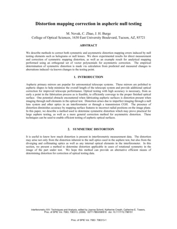
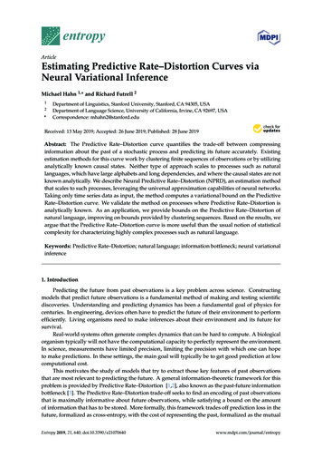
xout asig*kamp*knormendopIn addition to the single-sided formula above(components lie either above or below ω), Mooreralso provides a double-sided variation. Also, if weare careful with the spectral rolloff, a much simplernon-bandlimited expression is available: s t a k sin k k 0sin sin 21 a cos a(6)3.1In this case, we will not have a direct bandwidthcontrol. However, if we want to know what, forinstance, our -60dB bandwidth would be, we justneed to know the maximum value of k for ak 0.001. The normalising expression is also simpler: 1 a 2require time-varying spectra. More recently,research has shown that for certain waveshapes, wecan take advantage of other common functions,from the trigonometric, hyperbolic, etc., repertoire[16]. Some of these can provide smooth spectralchanges. We will look at the use of hyperbolictangent transfer functions to generate nearlybandlimited square and sawtooth waves. A usefulapplication of these ideas is in the modelling ofanalogue synthesiser oscillators (a field of researchalso known as Virtual Analogue Models).(7)The modified Csound code to match eq.6 isshown below:opcode NBlsum,a,kkkkikamp,kw,kt,ka,itb xinaphw phasor kwapht phasor ktHyperbolic tangent waveshapingA simple way of generating a (non-bandlimited)square wave is through the use of the use of thesignum function, mapping a varying bipolar input.This piecewise function outputs 1 for all non-zeropositive input values, 0 for a null input and -1 forall negative arguments. In other words, it clips thesignal, but in doing so, it generates lots ofcomponents above the Nyquist, which are dulyaliased. The main cause of this is the discontinuityat 0, where the output moves from fully negative tofully positive. If we can smooth this transition, weare in business.The Hyperbolic tangent is one such function thatcan be used instead of the signum, as it has asmooth transition at that point but it also preservessome of its clipping properties.a1 tablei aphw,itb,1a2 tablei aphw - apht,itb,1,0,1acos tablei apht,itb,1,0.25,1ksq ka*kaasig (a1 - ka*a2)/(1 - 2*ka*acos ksq)knorm sqrt(1-ksq)xout asig*kamp*knormendop3WaveshapingThe technique of waveshaping is based on thenon-linear distortion of the amplitude of a signal.This is achieved by mapping an input, generally asimple sinusoidal one, using a function that willshape it into a desired output waveform.Traditionally, the most common method of findingsuch function (the so-called transfer function) hasbeen through polynomial spectral matching. Themain advantage of this approach is that polynomialfunctions will precisely produce a bandlimitedmatching spectrum for a given sinusoid at a certainamplitude.However, the disadvantage is that polynomialsalso have a tendency to produce unnaturalsounding changes in partial amplitudes, if weIllustration 1: The Tanh() waveshaping functionIf we drive this function with a sinusoid input,we will be able to produce a nearly bandlimitedsignal. How bandlimited will depend on how hardwe drive it, as higher input amplitudes will producemore and more harmonics, and take less advantageof its smoothing properties.As with all types of waveshaping, the amplitudeof the input signal will determine signal bandwidth,in a proportional way. If we want to keep a steady
output amplitude, but vary the spectrum, we willneed to apply an amplitude-dependent scaling. Thisis generally done by using a scaling function thattakes the input amplitude as its argument andproduces a gain that can be applied to the outputsignal. We can then refer to the amplitude of theinput sinusoid as the distortion index.The code for general-purpose waveshaping isbased on standard function-mapping. It takes aninput sinusoid, maps it using table lookup and thenapplies the required gain, also obtained throughtable lookup:/* ar Waveshape kamp,kfreq,kndx,ifn1,ifn2,ifn3ifn1 is a sine/cosineifn2 is the transfer functionifn3 is the scaling function*/opcode Waveshape,a,kkkiiiendop4Asymmetrical FM synthesisWhile the technique FM, and to certain extentPhase Modulation (PM), too, synthesis are wellknown and have been explored in detail, some ofits variants have not. One interesting method thatseems to have been forgotten is the AsymmetricalFM proposed by Palamin et al[9]. In theirformulation, we have the original FM (or PM)model being ring-modulated by an exponentiatedsignal. This has the effect of introducing a newparameter that controls spectral symmetry thatallows the peaks to be dislocated above or belowthe carrier frequency. Their expression (excluding anormalisation factor) is:1s t exp 0.5 k r cos m r1sin c 0.5 k r sin m rkamp,kf,kndx,isin,itf,igf xinasin oscili 0.5*kndx,kf,isinawsh tablei asin,itf,1,0.5kscl tablei kndx,igf,1xout awsh*kamp*kscl endopFor hyperbolic waveshaping, we will need toprovide two function tables, for the transfer (tanh)and the scaling functions, respectively:f2 0 16385 "tanh" -157 157f3 0 8193 4 2 1The first Csound GEN draws tanh(x), over π/50, and the second automatically generates ascaling function based on the previous table (2). Tokeep aliasing at bay, the index of distortion (kndx)can be estimated roughly askndx 100/(kf*log10(kf))If we would like to generate a sawtooth waveinstead, we could take our square signal and applythe following expression:saw t square cos 1 (8)By heterodyning it with a cosine wave, we caneasily obtain the missing even components thatmake up the sawtooth signal. There will be a slightdisparity in the amplitude of the second harmonic(about 2.5 dB), but the higher harmonics will benearly as expected. This is a cheap way ofproducing a sawtooth wave.opcode Sawtooth,a,kkkiiikamp,kf,kndx,isin,itf,igf xinamod oscili 1,kf,1, 0.25asq Waveshape kamp*0.5,kf,kndx,isin,itf,igfxout asq*(amod 1) n (9)r n J k sin c n m The new parameter r is the symmetry control, r 1 pulling the spectral peak below the carrierfrequency ωc and r 1 pushing it above. It is avery nice feature which can be added at theexpense of a few multiplies and a couple of extratable lookups (for the cosine and the exponential).Note that what we have here is actually the ringmodulation of a waveshaper output (using anexponential transfer function) and the FM signal. Anice way of tying up two distortion techniquestogether.Implementing this is not too complicated. Theexponential expression needs normalisation, whichcan be achieved by dividing it by exp(0.5k[r - 1/r]).When coding this, we will draw up an exponentialtable from 0 to an arbitrary negative value (say -50)and then look it up with a sign reversal (exp(-x)).This allows us to use the limiting table lookupmechanism in case we have an overflow. Since thevalues of exp() tend to have little variation for largenegative values, limiting will not be problematic. Inaddition, to be faithful to the expression above(esp. in relation to component phases etc.), we willimplement PM instead of FM:/* ar Asfm kamp,kfc,kfm,kndx,kR,ifn1,ifn2,imaxifn1 is a sinewaveifn2 is an exp func between 0 and -imax*/opcode Asfm,a,kkkkkiiikamp,kfc,kfm,knx,kR,ifn,ifn2,imx xinkndx knx*(kR 1/kR)*0.5
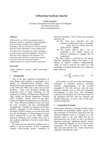
kndx2 knx*(kR-1/kR)*0.5afm oscili kndx/(2* M PI),kfm,ifnaph phasor kfcafc tablei aph afm,ifn,1,0,1amod oscili kndx2, kfm, ifn, 0.25aexp tablei -(amod-abs(kndx2))/imx, ifn2, 1xout kamp*afc*aexpThe complete Csound code of a more or lessliteral implementation of PAF is shown below:opcode Func,a,aasig xinxoutendop1/(1 asig 2)endopwith the exponential function table (ifn2) drawnfrom 0 to -imx (-50):f5 0 131072 "exp" 0 -50 1/* ar PAF kamp,kfun,kcf,kfshift,kbw,ifnifn is a sine wave*/opcode PAF,a,kkkkkikamp,kfo,kfc,kfsh,kbw,itb xinkn int(kfc/kfo)ka (kfc - kfsh - kn*kfo)/kfokg exp(-kfo/kbw)afsh phasor kfshaphs phasor kfo/2a1 tablei 2*aphs*kn afsh,1,1,0.25,1a2 tablei 2*aphs*(kn 1) afsh,1,1,0.25,1asin tablei aphs, 1, 1, 0, 1amod Func 2*sqrt(kg)*asin/(1-kg)kscl (1 kg)/(1-kg)acar ka*a2 (1-ka)*a1asig kscl*amod*acarxout asig*kampIn their original work, Palamin et al suggest adifferent method of normalisation. However, wefound that it does not work for all values of r andk, for which the above method will generally do.5PAFOne of the most recent new methods ofdistortion synthesis has been proposed by MillerPuckette in his PAF algorithm. In his paper[10], hestarts with a desired spectral description and thenworks it out as ring-modulation of a sinusoidcarrier and a complex spectrum (with low-passcharacteristics). As his interest is to create formantregions, he will use the sinusoid to tune a spectralbump around a target centre frequency. The shapeof the spectrum will be determined by hismodulator signal, which in turn is generated bywaveshaping using an exponentially-shapedtransfer function. So we have PAF, in its simplestformulation, as:s t M t cos c 1 g2 gf sin m cos c 1 g1 g2 n g n cos c n m endopThe waveshaping here is performed by directlyapplying the function, since there are no GENs inCsound which can directly generate such table.This is of course not as efficient as lookup, so thereare two alternatives: writing a code fragment to filla table with the transfer function, to be run beforesynthesis; or, considering that resulting distortedsignal is very close to a Gaussian shape, useGEN20 to create one such wavetable. A usefulexercise would be to reimplement the PAFgenerator above with table lookup waveshaping.6(10)1f x 1 x2 cg e BHere, the waveshaper transfer function is f(x).The signal has a bandwidth B, a fundamentalfrequency at ωm and its formant centre frequency isωc. To this basic formulation, where we expect ωcto be an integer multiple of ωm, a means of settingan arbitrary centre frequency is added (basically byusing a pair of modulators). In addition, thecomplete PAF algorithm provides a 'frequencyshift' parameter, which, if non-zero, allows forinharmonic spectra.Modified FM synthesisThe final method we would like to present hasbeen first briefly proposed by Moorer[4] in the1970s, but lay dormant until we have re-discoveredand explored some of its applications[16]. Thistechnique has been named by us Modified FMsynthesis (ModFM), as it is based on a slightchange in the FM algorithm, with some importantconsequences.An FM equation, when cast in complexexponential terms can look like this:s t ℜ{ei c iz cos m }(11)If we apply a change of variable z -ik to thethat formula, we will obtain the followingexpression:s t ℜ{ei c k cos m } ek cos m cos c (12)
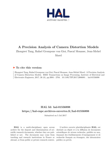
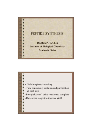
which, is, when multiplied by the normalisationfactor exp(-k), the basic Modified FM synthesisformula. One of the most important things aboutthis algorithm is revealed by its expansion:s t 1k { I 0 k cos c e I n k [cos c n m cos c n m ]}n 1(13)where In(k) are modified Bessel functions of thefirst kind, and constitute the basic (and substantial)difference between FM and ModFM.Theiradvantage is that they are (1) unipolar and (2) In(k) In 1(k), which means that spectral evolutions aremuch more natural here. In particular, the scaledmodified Bessels do not exhibit the much maligned'wobble' seen in the behaviour of Bessel functions(see fig. 2). That very unnatural soundingcharacteristic of FM disappears in ModFM.acar oscili kamp,kfc,isin,0.25acos oscili 1,kfm,isin,0.25amod table -kndx*(acos-1)/imx,iexp,1xout acar*amodendopWith ModFM, it is possible to realise typicallow-pass filter effects, by varying the index ofmodulation k. Also by using the carrier andmodulation frequency as the centre of a formantand the fundamental, respectively, it is possible toreproduce the effect of a band-pass filter (andPAF). In fact a variant of the ModFMimplementation above, with phase-synchronoussignals can serve as a very efficient alternative toPAF and other formant synthesis techniques, suchas FOF[17]7Final WordsIn this article, a short tutorial on variousdistortion synthesis algorithms was offered. Wehave concentrated, particularly, on less wellknown and more recent techniques. These methodshave a common trait of offering elegant and lowcost solutions to the problem of generatingcomplex time-varying spectra. They provide thesound designer an excelent alternative to othermore computationally intensive and multiparameter techniques.8AcknowledgementsThis research was partly funded by a grant fromAn Foras Feasa, the Humanities Institute, NUI,Maynooth.ReferencesIllustration 2: Scaled Modified Besselfunctions orders 0 through 3There are several applications of ModFM (asthere are of FM) as well as small variations in itsdesign. We will present here a basic straightimplementation of the algorithm. Further examplesand applications will be discussed in forthcomingarticles. The Csound code uses, as in a previousexample, table lookup to realise the exponentialwaveshaper in the ModFM formula. Apart fromthat, all we require is two cosine oscillators,yielding a very compact algorithm/* ar ModFM kamp,kfc,kfm,kndx,ifn1,ifn2,imaxifn1 is a sine waveifn2 is an exponential between 0 and -imax*/opcode ModFM,a,kkkkiiikamp,kfc,kfm,kndx,isin,iexp,imx xin[1] Chowning, J. 1973,"The Synthesis of ComplexAudio Spectra by Means of FrequencyModulation." Journal of the Audio EngineeringSociety (21): 526-34.[2] Windham, G. and K. Steiglitz 1970, “InputGenerators for Digital Sound Synthesis”. Journalof the Acoustic Society of America, 47(2): 665-6.[3] Moorer, J. A. 1976,“The Synthesis ofComplex Audio Spectra by Means of DiscreteSummation Formulas”. Journal of the AudioEngineering Society, 24 (9).[4] Moorer, J. A. 1977,“Signal Processing Aspectsof Computer Music: A Survey”, Proceedings ofthe IEEE, 65 (8): 1108 – 1141.[5] Arfib, D. 1978,“Digital Synthesis of ComplexSpectra by Means of Multiplication of NonLinear Distorted Sinewaves”. AES PreprintNo.1319 (C2).
[6] Le Brun, M. 1979,“Digital WaveshapingSynthesis”. Journal of the Audio EngineeringSociety, 27(4): 250-266.[7] Schottstaedt, W. 1977, “ The Simulation ofNatural Instrument Tones Using a ComplexModulating Wave”. Computer Music Journal1(4): 46-50.[8] Le Brun, M. 1977,“A Derivation of theSpectrum of FM with a Complex ModulatingWave”, Computer Music Journal, 1(4):51-52[9] Palamin, J.P., P. Palamin and A. Ronveaux1988,”A Method of Generating and ControllingMusical Asymmetric Spectra”. Journal of theAudio Engineering Society 36 (9): 671-685[10] Puckette, M. 1995, "Formant-Based AudioSynthesis Using Nonlinear Distortion." Journalof the Audio Engineering Society 43(1): 40-47.[11] Lazzarini, V., J. Timoney and T. Lysaght2008,“Split-Sideband Synthesis”. Proceedings ofthe ICMC 2008, Belfast, UK,[12] Lazzarini, V., J. Timoney and T. Lysaght2007,“Adaptive FM synthesis”. Proceedings ofthe 10th Intl. Conference on Digital AudioEffects (DAFx07). Bordeaux: University ofBordeaux: 21-26.[13] Lazzarini, V., J. Timoney and T. Lysaght2008,“The Generation of Natural-SyntheticSpectra by Means of Adaptive FrequencyModulation”. Computer Music Journal, 32 (2):12-22.[14] Lazzarini, V., J. Timoney and T. Lysaght2008,“Asymmetric Methods for Adaptive FMSynthesis”. Proceedings of the InternationalConference on Digital Audio Effects, Helsinki,Finland.[15] Cabrera, A. (Ed.). The Csound Manual. http://csounds.com/manual.[16] Lazzarini, V., J. Timoney, 2008, "NewPerspectives on Distortion Synthesis for VirtualAnalogue Oscillators". Submitted to ComputerMusic Journal.[17] Rodet, X. 1984. “Time Domain FormantWave-Function Synthesis”. Computer MusicJournal, 8 (3):9-14.
A Distortion Synthesis Tutorial Victor Lazzarini An Grúpa Theicneolaíocht Fuaime agus Ceoil Dhigitigh NUI Maynooth Ireland Victor.Lazzarini@nuim.ie