Transcription
DistortionbyB. Hönlinger and H. H. NasseCarl ZeissCamera Lens DivisionOctober 2009
Preface“I found somebody say ‘terrible moustachedistortion’, but I don’t see any distortion at all”.As you can see in above statement in a forum discussion onecan have very different opinions about distortion of lenses. Forsome photographers straight lines are of low importance or theirsubjects don’t have them. Others strive for perfection and spenda lot of efforts, to heal geometric aberrations at least in theimage post-processing.Those who try to avoid these efforts search for lenses whichdeliver perfect quality right from the beginning without laterimprovements. At this point the problem with numbers arises,because absolute perfection exists only in a few types. Mostlenses exhibit at least small distortion errors, and to decidewhether they are acceptable, one has to understand thenumbers in data sheets and in lens test publications. This issueof Camera Lens News tries to support you a little bit inunderstanding this matter.And since distortion is of major importance in wide-angle lenses,we will in addition deal with some other strange effects typical forthis class of lenses, so that you understand why imagecomposition with the short ones is at the same time so difficultand attractive.Carl ZeissCamera Lens DivisionOctober 2009
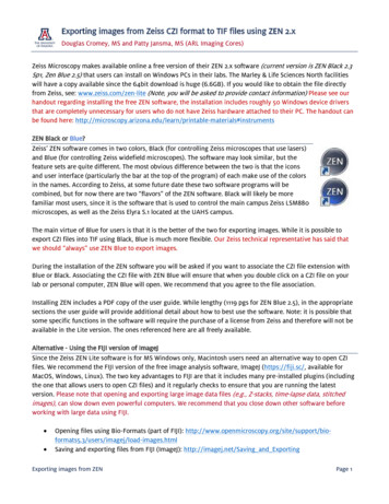
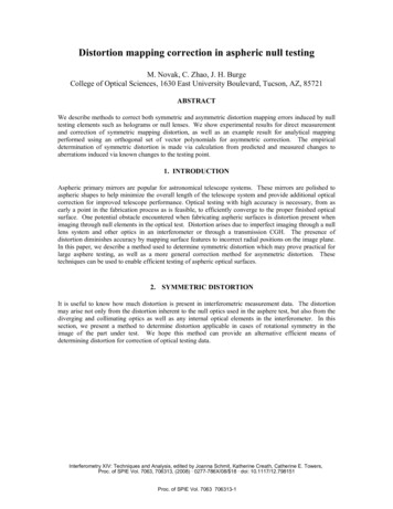
What is distortion?The majority of camera lenses produceimages in line with the laws of centralperspective. This kind of projection of threedimensional space onto a two-dimensionalimage surface is also called gnomonicprojection. This Greek term (γνομον gnomon shadow-producing rod) denotes atype of sundial because, as with a sundial, animage point is produced by connecting apoint in the object space to the center of theprojection using a straight line; the imagepoint is where this straight line intersectsthe flat projection surface.In painting, central perspective wasinvented during the time of Renaissance.The methods used by the artist to strictlyapply this perspective are shown to us byAlbrecht Dürer:Instructions in the application of perspective, woodcarving by Albrecht Dürer,approx. 1527The center of projection of the image is thetip of the rod used by Dürer's artist to drawattention to the charms of the young ladyin this picture. The projection surface isthe frame fitted with a grid placed betweenthe two, and it is used by the artist totransfer the image points onto his drawingpaper with the proper perspective.The center of projection of camera lensesis their entrance pupil, i.e. the image ofthe aperture stop viewed from the front.When taking panorama photos, it isnecessary to swivel around the entrancepupil to ensure that objects in theforeground and background are not shiftedwith respect to each other.This special point is often also called thenodal point, but this term has a verydifferent meaning in optics. There isnothing particularly mysterious about theentrance pupil either, since anyone cansee it without any special aids andestimate its approximate position.Carl ZeissHowever, the entrance pupil is not thephysical aperture stop, but rather its virtualimage – and as such may even besituated outside the lens altogether. Thisis often the case with short telephotolenses.The gnomonic (central perspective)projection has the special feature whereall straight lines of the object space arereproduced in the image as a straight lineagain regardless of where they aresituated and to where they are projected.Lenses with this property are called‘rectilinear’. During the history ofphotographic lenses they appeared first inththe sixties of the 19 century.Distortion is defined as a lens aberration inwhich this property is no longer exactlyfulfilled. A lens that exhibits distortionproduces slightly curved images of allthose lines that do not pass through thecenter of the image. Thus this effect isalso called ‘curvilinear distortion’.Camera Lens Division3 / 28
What can we learn from the data sheet of the lens?The reason for the curved images ofstraight lines is that the image scale is notconstant throughout the entire image field.In other words: the focal length of a lensshowing distortion changes with thedistance of an image point from the opticalaxis.If the reader allows me to use thelanguage of mathematics, it will be mucheasier to comprehend what the numberswe use to describe distortion actuallymean.Let us first look at the image equation of arectilinear lens with ideal gnomonicprojection:u ' f ' tan WW is the object-side field angle, i.e. theangle between the optical axis and the linefrom the object point to the entrance pupil,u’ is the off-axis distance, i.e. the distanceof the image point from the optical axis. Toexpress this equation in words: the off-axisdistance is proportional to the tangent ofthe field angle, and the focal length f’ isthe proportionality constant.I would now like to mention that this isexactly how the focal length of lenses isdefined and measured: one measures theangle to the optical axis and the off-axisdistance of the corresponding image pointcreated by a ray of light arriving from asource at an infinite distance. You mayalso encounter measurements, in whichthe focal length is calculated in the nearrange from the distance and image scalefactor. However, this result often deviatessubstantially from the specifications of themanufacturer.However, this does not necessarily meanthat the manufacturer has cheated vastly.Many lenses change their focal lengthwhen focused on short distances, andcalculations of this kind fail to take intoaccount other lens parameters such asprincipal plane distances. For this reason,a long zoom lens, for example, often hassmaller object fields at short distancesthan a comparable prime lens.* In optical tradition the off-axis distance of an imagepoint I also called ‘image height’. This should not beconfused with the vertical frame length.Carl ZeissAnother factor must be included in thegnomonic image equation if the focallength is not constant throughout the fieldof view: D% u ' f ' 1 tan W 100 D is the measure of the distortion error. IfD 0, the term in parentheses is equal to 1,and the situation is the same as with theideal lens.If D is a positive number, the term inparentheses is larger than 1. The off-axisdistance u’ is then larger than with thedistortion-free lens of the same focallength. Since the distortion increases withincreasing distance in most cases, arectangle is distorted to a pincushionshape. We shall see later though thatpincushion-shaped images can also occurwith negative values of D.If D is a negative number, the term inparentheses is smaller than 1. The off-axisdistance u’ is then smaller than with thedistortion-free lens of the same focallength. The lines of a rectangle arebulging and we call this a barrel shape.In both cases considered here, the imagepoint is shifted in a radial direction, i.e. onthe radius of the field of view. Accordingly,parameter D is also called radialdistortion. Our data sheets specify theradial distortion by means of a curve, i.e.as a percentage value as a function of theoff-axis distance *.This curve contains all information aboutthe geometric properties of the lens. Forproper interpretation, though, we need tounderstand it even better. What makes oureyes so sensitive to distortion? Taking aphoto of concentric circles, for example atarget for shooting practice, we can barelyrecognize distortions as long as theyremain moderate since we have littlefeeling for the correct absolute size of acircle. In contrast, we can see pretty wellthat straight lines are reproduced withsome curvature, i.e. we need tounderstand the relationship between radialdistortion and this kind of bending ofstraight lines.Camera Lens Division4 / 28
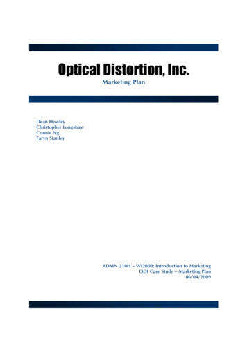
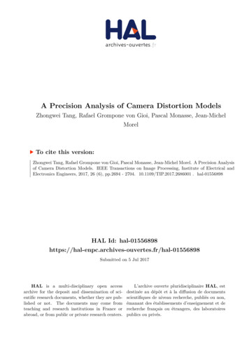
Radial distortion and TV distortionTypes of distortion1. Pincushion .20.10.00481216Radial distortion [mm]-Radial distortion [%]-Pincushion distortion at an already detectablelevel in a lens for the 35mm format isdescribed by the following curve:20Off-axis distance [mm]The black curve shows that the radialdistortion error increases gradually from zeroin the middle of the image to 3% in the cornerof the image where the focal length is 3%larger than in the middle.The red curve shows the absolute magnitudeof the radial shift of the image points in unitsof millimeters. These values tell us thatdistortion shift is more than ten times largerthan the usual circle of confusion. Thusperceivable distortion is nearly never causedby poor build quality or shock damage of thelens. Distortion is not an issue for repairservice, it is determined by the lens design.And distortion is not changed by stoppingdown.Looking at this curve, one keeps in mind:"The lens exhibits a 3% distortion", but mightthen be surprised if a test report claims: "Thelens shows 1.1% pincushion distortion". Howcan we reconcile this apparent discrepancy?Well, the test report does not refer to radialdistortion, but rather to TV distortion. This isa measure of how strongly the image of astraight line that is situated at the edge of theimage (in particular on the long edge of theimage in a rectangular format) is curved. Thisamplitude of curvature is then related to thetotal frame height and expressed as apercentage value.It is therefore very important to note whichpercentage value is actually meant. Thevalues of TV distortion are always smallerthan the radial distortion specified by us.Carl ZeissDTV ΔH 100HSometimes the total height difference ofthe distorted rectangle is related to theframe height. This is then twice the abovefigure.In order to understand how these fairlydifferent numbers arise, let us look at aline at the upper edge of the 35mm format.A point in the middle of this line has adistance of 12 mm from the middle of theimage. Here, the lens shows approx. onepercent radial distortion. Consequently,the image of this line is not only curved,but also shifted by 0.12 mm. However, wedo not notice this.If we travel along the line until we get tothe corner, the off-axis distance increasesfrom 12 to 21.6 mm and, according to thecurve presented above, the radialdistortion increases to 3.1% in theprocess. The endpoint of the line istherefore shifted in a radial direction by0.031 x 21.6 0.67 mm. However, in the24x36 rectangle of the 35 mm format, thediagonal is inclined by 56 with respect tothe vertical direction. Splitting the radialdistortion into horizontal and verticalcomponents, the distortion shift in thevertical direction is 0.67 x cosine(56 ) 0.37 mm. Accordingly, the vertical shift ofthe image points in the middle of the lineand at its end is 0.12 mm and 0.37 mm,respectively. The amplitude ΔH is thedifference between these two values, i.e.0.25 mm. This corresponds to approx.1.1% for a frame height of 24 mm.Camera Lens Division5 / 28
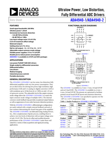
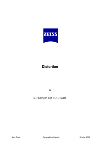
TV-Distortion at long edge 1.1 %This diagram shows a simulated image characterized by the pincushion distortiondescribed above. The crosses are the image points that are imaged with distortion error.The thin red lines are reference lines without curvature. For reasons of symmetry, it issufficient to show just one quarter of the image, meaning that the middle of the image issituated in the lower left corner of the graph. The blue lines show the crop factor of 050.20TV distortion [%]-Amplitude of curvature[mm]TV distortion at long edge 1.1 %005101520Line distance from centre [mm]horizontal, barrelwave typewave typepincushionpincushionvertical, barrelEach point in this graph represents the amplitude of line curvature plotted over thedistance of the line from the image centre. The amplitude of curvature increases uniformlyfrom the middle towards the edge in this distortion profile. TV distortion values usuallyrefer to a line on the long edge of the image (symbol filled in blue). Curvature is lesspronounced on the short edge, since this line proceeds only through off-axis distancesbetween 18 and 21.6 mm.Carl ZeissCamera Lens Division6 / 28
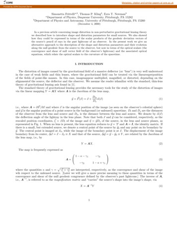
2. Barrel distortionA lens with substantial barrel distortion ofstraight lines shows negative radial distortionwhose absolute amount increases towardsthe corner:0481216Let us have the negative radial distortiondrop just a little bit more, let's say to -7% i.e. it is 1.4 times larger than before:200-1.00.012-2.0-3.018-4.022-5.0-6.0Radial distortion [%]-Radial distortion 8.0Off-axis distance [mm]Off-axis distance [mm]The lens reaches -5% radial distortion in thecorner of the image, which is a typical valueof many wide-angle to tele zoom lenses atshortest focal length.The curvature of a peripheral line at the longedge of the format is easy to calculate. Weneed to bear in mind that the radial distortionin the corner needs to be multiplied by thecosine of 56 0.55 in order to take intoaccount only its contribution to the shift in thevertical direction.DTV (21.6 x 0.05 x 0.55 – 12 x 0.02)/24Values like this do indeed occur with reallife lenses when these are used outsidetheir normal field of application, e.g. a zoomlens in an extreme macro-photographysetting.The same calculation for the long edge ofthe format as before yields:DTV (21.6 x 0.07 x 0.55 – 12 x 0.01)/24This means approx. 3% TV distortion forthis line - quite a bit. Although we increasedthe maximal radial distortion by only 40%,we managed to double the TV distortion.Result: 1.5 % TV distortion.Similarly, we can calculate the curvature of aperipheral line at the short edge of the format,but now have to take into account theinclination of the diagonal with respect to thehorizontal direction. This angle is only 34 and the cosine of 34 is 0.83.DTV (21.6 x 0.05 x 0.83 – 18 x 0.04)/24The result obtained (0.73%) is smaller again,as expected.This shows how easy it is to get lost in thedense forest of percentage values! Let medemonstrate this even
Distortion is defined as a lens aberration in which this property is no longer exactly fulfilled. A lens that exhibits distortion produces slightly curved images of all those lines that do not pass through the center of the image. Thus this effect is also called ‘curvilinear distortion’. Carl Zeiss Camera Lens Division 3 / 28