Transcription
FTXASSEMBLY & OPERATION MANUALRECORD SERIAL NUMBER HEREwww.inspirefitness.comby Health In Motion LLCJuly 2018
CONGRATULATIONS You’ve just taken the first step to a healthierand stronger body. This multi-gym by Inspire offers the key to unlockingyour body’s potential. Regular strength training on a multi-gym has beenshown to deliver a host of benefits including: increased muscle tone,decreased body fat, improved energy levels, a reduction in stress, andimproved cardiac output. Once again, congratulations, you are on your wayto improving your self image, overall health, and quality of life.BEFORE ASSEMBLING YOUR HOME GYMIMPORTANT: Read this entire manual before attempting to build or usethis machine. This manual contains step by step instructions for properassembly.Use the parts list included in this manual to verify that all parts areaccounted for before assembly. If any parts are missing, contact the retailerof this multi-gym for replacement parts. Or, call Inspire at 877-738-1729.Make sure that adequate room has been cleared before attempting to buildyour multi-gym. A rubber mat is recommended for use under yourmulti-gym to protect wood flooring or carpeting from damage duringassembly and usage.This multi-gym is intended for indoor use only. Rust can form on certainparts including guide rods in a humid environment, resulting in impairedfunction.Service of your multi-gym should only be performed by an authorizedInspire retailer. Service performed by anyone else can result in loss ofwarranty. If you need help finding an authorized retailer, please contact usdirectly:Inspire Fitness255 Airport Cir, Suite 101Corona, CA 92880Ph: 877-738-1729Fx: 714-738-1728www.inspirefitness.com7/1018
TABLE OF CONTENTSSection Description .PageImportant Safety Instructions .1Tools Required 1Parts & Hardware List .2-4Exploded View .5Assembly Instructions .6-11Decal Placement 12General Maintenance Information . 13Maintenance Schedule . 14Limited Warranty .157/2018
IMPORTANT SAFETY NOTICE PRECAUTIONSThis exercise machine is built for optimum safety. However, certainprecautions apply whenever you operate a piece of exercise equipment. Besure to read the entire manual before you assemble or operate yourmachine. In particular, note the following safety precautions:1. Keep children and pets away from the machine at all times. DO NOTleave children unattended in the same room with the machine.2. Only one person at a time should use the machine.3. If the user experiences dizziness, nausea, chest pain, or any otherabnormal symptoms, STOP the workout at once. Consult a Physician.4. Position the machine on a clear, leveled surface. Do not use outdoors.5. Keep hands away from all moving parts.6. Always wear appropriate workout clothing when exercising. Running oraerobic shoes are also required when using the machine.7. Use the machine only for its intended use as described in this manual.8. Disabled persons should not use the machine without a qualified personor physician in attendance.9. Always do stretching exercises to properly warm up before usingmachine.10. Never operate the machine if it is not functioning properly.11. A spotter is recommended during exercise.TOOLS REQUIRED FOR ASSEMBLYTools Required for Assembling the Machine: Adjustable Wrench and AllenWrenches. NOTE: Two or more people assembling this machine is a must.DO NOT attempt to assemble this machine alonePAGE 17/2018
part listPart#DescriptionPart NumberQ'ty(pcs)12345Right Station AssemblyGM692200408PZ1Left Station AssemblyGM692200409PZ1Upper Frame AssemblyGM692220002PZ021Lower Cross BraceGM690260001PT01051Upper Cross BraceGM692300004PT010516Guide Rod Bracket & Ring CapGM692381001PT0105GM692-881-0022Guide RodGM692-381-0024Selector Stem AssemblyGM692500003PZ102Weight Selector 252627282930313230Weight PlateRopeGM692-881-0111Curl BarGM691320003PZ021Single HandleGM660820001WX072Chin Up BeltGM692-400-005SK1Height Adjustment HandleGM691-880-003SK2Rubber BumperGM692-881-0034Hook0200-070-0822M10 x 80 Allen Bolt0113-210-8064M10 x 70 Allen Bolt0113-210-7088M10 x 25 Allen Bolt0113-210-2584M10 x 19 Allen Bolt0113-210-2084M5 x 10 Allen Bolt0113-705-0882Ø 10 Lock Washer0116-310-0288M10 Aircraft Nut0110-710-0088Ø 10 Washer0116-210-50828Resistance Label SetGM692-900-0012U-shaped Pulley BracketGM692-500-0022Ø 2” Tension Adjustment PlateGM690-501-0062M10 x 2” Allen Bolt0113-210-5082PulleyGM692-880-0012Right Lock SwitchGM690-320-0031Left Lock SwitchGM690-320-0041Tool List333435#6 Allen Wrench (Tool)0511-606-031#4 Allen Wrench (Tool)0511-604-01114#&17# Wrench (Tool)M330-561-0021Page 27/2018
HARDWARE SIZING CHARTPage 37/2018
Page 47/2018
Page 57/2018
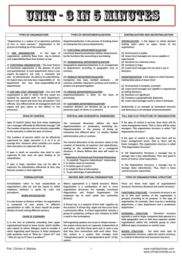
FUNCTIONAL TRAINER ASSEMBLY INSTRUCTIONSSTEP 1A.) Do not tighten the Nuts and Bolts until instructed to do so.B.) Place the Lower Cross Brace (#4) between the Right & LeftStations (#1 & #2) in the mid-span.C.) Attach one end of the Lower Cross Brace to the Right Station.Secure it with two M10 x 70” Allen Bolts (#20), four Ø 10” Washers(#25), and two M10 Aircraft Nuts (#24). Repeat the sameprocedure to install the other side.D.) Repeat Procedure B & C to install the Upper Cross Brace (#5).E.) Place the Pull Up Bar Assembly (#3) on top of the Right and LeftStations.F.) Secure each end with two M10 x 25” Allen Bolts (#20), two Ø 10” Lock Washers (#23), and Ø 10” Washers (#25).G.) Securely tighten all Nuts and Bolts installed.Page 67/2018
Page 77/2018
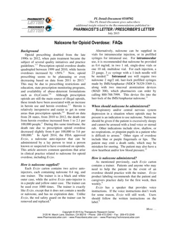
STEP 2A.) Lift up the Selector Stem (#8) on the Right Station (#1) andhold it still to release the tension on the cables. Remove the twoM10 x 20” Allen Bolts (#21), Ø 10 ” Spring Washers (#24), and Ø10” Washers (#25) which were pre-assembled in the factory to holdthe Guide Rod Bracket (#6).B.) Pull the two Guide Rods (#7) away from the Upright. Removethe Guide Rod Bracket (#6) from the top of the Guide Rods.C.) Remove the Selector Stem (#8) from the Guide Rods.D.) Slide fifteen 10lb Weight Plates (#10) from the top of GuideRods down to the Rubber Bumpers (#16). Make sure the weightsticker cut out is facing the inside of the machine.E.) Slide the Selector Stem back onto the Guide Rods. Hold theSelector Stem above the weight stack to make it easier to re-installGuide Rods and Bracket.F.) Re-install the Guide Rod Bracket (#6) onto the Guide Rods.G.) Push the Guide Rod Bracket back into the upright.H.) Secure the Bracket back to the upright frame with the two M10x 20 ” Allen Bolts (#21), Ø 10 ” Spring Washers (#23), Ø 10”Washers (#25).I.) Lower the Selector Stem down onto the top of the weight stack.J.) Check all the cables to make sure they are on track on thepulleys.K.) Peel off the weight resistance label from the Resistance LabelSet (#26) and attach to the plates.L.) Insert the Weight Selector Pin (#9) into the weight stack.M.) Lubricate the Guide Rods with super lube or lube provided.N.) If Needed, Adjust the Cable tension by first loosening the M10 x2” Allen Bolt located on the Selector Steam Assembly (#8) thenrotate the Tension Adjustment Plate (#31) clock orcounterclockwise to move the Bolt and the Large Pulley (#30) upand down along the open track inside the U-shaped Pulley Bracket(#27). Once desired tension is achieved, securely tighten the Bolt(#8) back.O.) Repeat the Procedure A through N above to install the other setof weight plates to the Left Station (#2).Page 87/2018
Page 97/2018
STEP 3A.) Attach the Height Adjustment Handle (#15) to the Right LockSwitch (#32) on the Pulley Carriage. (Not shown on diagram) Andsecure it with one M5 x 10” Allen Bolt (#22). Repeat the sameprocedure to install the other side.B.) Connect the Single Handle (#13) to the Cable (#2) on the RightStation (#1) with a Spring Clip (#17). Repeat the same procedureto install the other side.D.) Lift up the Height Adjustment Handle (#15) and slide the PulleyCarriage along the Pulley Carriage Support Frame to the selectedlevel. Release the Handle to lock the Pulley Carriage in position.E.) Store Curl Bar (#12), and Rope (#11) onto theHanger Bracket behind the Upper Cross Brace (#5). Hang Chin UpBelt (#14) on Upper Cross Brace (#5).Page 107/2018
Page 117/2018
DECAL PLACEMENTPage 127/2018
GENERAL MAINTENANCE INFORMATION Periodically inspect the cables for splitting, cracking or fraying. Also,watch for bulging or flat areas in the cable. Immediately replace cables at the first signs of damage or wear. Neveruse equipment with damaged or worn cables. Cables naturally stretch over time, so check cable slack periodically andadjust cable tension as needed. Regularly inspect product for loose hardware. Do not use or store equipment outdoors. Inspect snap links, swivels, handles, and weight stack pins for wear ordamage. If wear or damage exists, replace immediately. Locate and familiarize yourself with all warning decals on the multi-gym. Replace damaged or worn upholstery immediately. Periodically wipe down guide rods with a dry cloth and re-apply a thin coatof a Teflon-based lubricant.Page 137/2018
MAINTENANCE SCHEDULEROUTINEHOMEMAINTENANCEInspect: Links, Pull Pins,Spring Clips, Swivels,Weight Stack PinsWEEKLYClean: UpholsteryWEEKLYInspect: Cables andtheir FittingsWEEKLYInspect: Tautness of allShroudsWEEKLYInspect: Accessory Barsand Handles3 MONTHSInspect: All Decals3 MONTHSInspect: All Nuts andBolts. Tighten if Needed3 MONTHSInspect: Anti-Skidsurfaces3 MONTHSClean and Lubricate:Guide Rods with a Teflonbased lubricant3 MONTHSLubricate: Seat Sleevesand all Plastic Slides3 MONTHSClean and Wax: AllGlossy FinishesYEARLYReplace: Cables, Beltsand Connecting Parts2 YEARSPage 14ENTRY DATE7/2018
Warranty.This Warranty applies to Inspire Strength products manufactured or distributed by Health In Motion LLC.CONSUMER USE:LIMITED LIFETIME FRAME:Includes Frame and WeldsLIMITED LIFETIME PARTS:Includes Upholstery, Hardware, etc.LIMITED LIFETIME MOVING PARTS:Includes Pulleys, Cables, etc.PLEASE NOTE THIS INSPIRE PRODUCT IS NOT MADE FOR COMMERCIAL USEUsing a non-commercial product in a commercial setting can result in serious injury or death!Health In Motion warrants that the Product you have purchased for light-commercial, personal, family or household use from Health InMotion LLC or from an authorized Health In Motion reseller is free from defects in materials or workmanship under normal use duringthe warranty period. Your sales receipt, showing the date of purchase of the Product, is your proof of the date of purchase. Thiswarranty extends only to you, the original purchaser. It is not transferable to anyone who subsequently purchases the Product fromyou. It excludes expendable parts such as paint and finish. This Warranty becomes VALID ONLY if the Product is assembled /installed according to the instructions / directions included with the Product.Replacement and repair of parts.During the warranty period Health In Motion will, at no additional charge, repair or replace the Product if it becomes defective,malfunctions, or otherwise fails to conform with this Warranty under normal light-commercial, personal, family, or household use. Inrepairing the product Health In Motion may replace defective parts with, at the option of Health In Motion, serviceable used parts thatare equivalent to new parts in performance, or new parts. All exchanged parts and Products replaced under this warranty will becomethe property of Health In Motion. Health In Motion reserves the right to change manufacturers and or specification of any part to coverany existing warranty.Service procedures.To obtain warranty parts, you must return the parts to Health In Motion or an authorized Health In Motion retailer in its original container(or equivalent). You must pre-pay any shipping charges, taxes, or any other charges associated with transportation of the Product. Inaddition, you are responsible for insuring any Product shipped or returned. You assume the risk of loss during shipment. You mustpresent Health In Motion with proof-of-purchase documents (including the date of purchase, Model, and Serial Number). Any evidenceof alteration, erasing or forgery of proof -of-purchase documents will be cause to void this Warranty. Register your warranty online visitwww.inspirefitness.comConditions and Exceptions.This Warranty does not extend to any Product not purchased from Health In Motion LLC or from an authorized Health In Motionreseller. This Warranty does not extend to any Product that has been damaged or rendered defective; (a) as a result of accident,misuse, or abuse; (b) by the use of parts not manufactured or sold by Health In Motion; (c) by modification of the Product; (d) as a resultof service by anyone other than Health In Motion, or an authorized Health In Motion warranty service provider; (e) product that has notbeen properly maintained (follow maintenance schedule found on product). Should any product submitted for Warranty service befound to be ineligible, an estimate of repair cost will be furnished and the repair will be made if requested by you upon Health In Motionreceipt of payment or acceptable arrangement of payment.DisclaimerEXCEPT AS EXPRESSLY SET FORTH IN THIS WARRANTY HEALTH IN MOTION MAKES NO OTHER WARRANTIES;EXPRESSED OR IMPLIED INCLUDING ANY IMPLIED WARRANTIES OF MERCHANTABILITY AND FITNESS FOR A PARTICULARPURPOSE. HEALTH IN MOTION EXPRESSLY DISCLAIMS ALL WARRANTIES NOT STATED IN THIS WARRANTY. ANY IMPLIEDWARRANTIES THAT MAY BE IMPOSED BY LAW ARE LIMITED TO THE TERMS OF THIS WARRANTY. NEITHER HEALTH INMOTION NOR ANY OF ITS AFFILIATES SHALL BE RESPONSIBLE FOR INCIDENTAL OR CONSEQUENTIAL DAMAGES. HEALTHIN MOTION IS NOT RESPOSIBLE FOR THE REPAIR OR REPLACEMENT OF ANY PARTS THAT HEALTH IN MOTIONDETERMINES HAVE BEEN SUBJECTED AFTER THE DATE OF MANUFACTURE TO ALTERATION, NEGLECT, ABUSE, MISUSE,NORMAL WEAR & TEAR, ACCIDENT, DAMAGE DURING TRANSIT OR INSTALLATION, FIRE, FLOOD, OR ANY ACT OF GOD.SOME STATES DO NOT ALLOW LIMITATIONS ON HOW LONG AN IMPLIED WARRANTY LASTS OR THE EXCLUSION ORLIMITATION OF INCIDENTAL OR CONSEQUENTIAL DAMAGES, SO THE ABOVE LIMITATIONS OR EXCLUSION MAY NOTAPPLY TO YOU. This Warranty gives you specific legal rights and you may also have other rights that may vary from state to state.This is the only express warranty applicable to Health In Motion’s “Inspire” branded strength products. Health In Motion neitherassumes nor authorizes anyone to assume for it any other express warranty.Page 157/2018
FUNCTIONAL TRAINER ASSEMBLY INSTRUCTIONS STEP 1 A.) Do not tighten the Nuts and Bolts until instructed to do so. B.) Place the Lower Cross Brace (#4) between the Right & Left Stations (#1 & #2) in the mid-span. C.) Attach one end of the Lower Cross Brace to the Right Station. Secure it