Transcription
Bob Brehm, AK6RChief EngineerPalomar-Engineers.comHAMCON 2017 - September 2017This presentation available on websiteCopyright 2013-2017 Palomar Engineers, Inc.
Are you the SOURCE of RFI?IT’S ALL YOUR FAULT WITH THAT BIG ANTENNA!
Are you a VICTIM of local RFI? RFI SourcesHam AntennaRadiating CoaxElectronic DevicesSolar SystemsGrow LightsHVAC motorPlasma TVDSL/RoutersSwitching powerSuppliesWasher/Dryer orother appliancesQRN - High Noise Floor – Weak Signals – NO DX – No fun!
RFI Workshop Objectives Learn fundamentals of RFI - identify symptoms, pinpoint causes & apply simple curesWhat’s a ferrite filter and how to choose & buy the rightferrite for your RFI issueHow to use ferrites to solve the #1 RFI problem shared byall hams using coax-fed HF antennasHow to use ferrites to solve transmitter RFI problems,reduce your receiver noise floor, and keep your neighbor’sand spouse happy!Understand CONCEPTS with little or NO MATH requiredThinking cap time
For Contesters, DX’ers, Rag Chewers, OldTimers and Beginners too!
What is RFI? Radio Frequency Interference/ElectromagneticInterference (RFI/EMI) – (100 KHz – 2 GHz) A radio frequency disturbance that causes a malfunctionto an electrical circuit so it functions improperly. Common Sources Natural: Sun, Cosmic noise, Lightning, atmospheric staticRadio Transmitters (Amateur, broadcast, consumer devices)Motors, ignition systems, power lines, square wave generators Common Victims Any electronic device that malfunctions or experiences a highnoise level by acting as an unintended “receiver” of RFI
Got RFI in your shack/home? TX Symptoms – caused by your transmitter or antenna Hot microphone – lip burns, distorted audio Resonant length antennas don’t tune correctly or high SWR Your voice/transmission causes interference with consumerelectronic devices acting as ham radio frequency “receivers”(e.g. computers, TV/audio system, security system, garagedoor opener, telephone, sprinkler systems, etc.) Wife Alarm goes off RX Symptoms – caused by sources outside your shack High receive noise level not due to atmospheric conditions Birdies, chirps, buzzes, clicks, broadband noise on receiver Distorted receiver audioHow did you get RFI?
How is RFI Transferred?All three parts mustbe present to have anRFI problem.Multiple paths arevery common:1. Radiative - air2. Conductive - wire3. Inductive - wire4. Capacitive - wireHow to identify the path(s)
Typical RFI receiving “antennas" 160-80-60-40-30 meter transmitters – “Long” - AC power lines,telephone/DSL lines, satellite/cable coax, long Ethernet cables,antenna feed line coax shield, antenna control/rotor cables, 2ndstory ground wires AM Broadcast Transmitter RFI – same as 160 – long “antennas” 20-6 meter transmitters – “Short” - speaker wires, deviceinterconnect cables, mic cables, short Ethernet cables FM Broadcast Receiver RFI – short “antennas” – 3-6 feet long –device interconnect cables “Antennas” pick up RFI radiation and a common mode current isinduced on ALL conductors from an RFI SOURCEHow do we stop or reduce this current?
Reduce RFI current to reduce RFI Typical solutions: Resonant traps, ferrites, filters with high choking impedanceFerrites are your friend
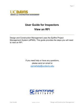
Ferrite Topologies (Shapes)Slip On BeadSnap On BeadToroid or RingFuzzy Ferret – not!CHARACTERISTICS Cheap, easy to install, suppress RFI from 100 KHz - 2 GHz Work on all conductive paths (antenna feed line, AC/DC, I/O cables) Lots of options in size, shape to suppress most RFI path currents Are effective if you understand how to choose the correct ferrite andwhere to install the ferrite for a particular RFI problemHow do ferrites work?
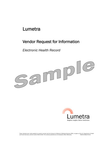
How do Ferrites Work?Simple Equivalent CircuitFerrite beads are categorized by three response regions: inductive, resistive,and capacitive. To reduce high frequency interference (noise), the bead mustbe used in the resistive region where it acts like a resistor, which impedes thehigh frequency noise and dissipates it as heat.How can resistance be increased?
Ferrite resistors add in seriesMorebeads Impedancehigherchoking R(up to 30MHz)Frequency Impedance (Z) Resistance /- Reactance
Choking Z Increases with (turns)2 If 1 turn Z, 2 turns 4Z, 3 turns 9 Z More Z less wire current less RFI radiated fromwire or induced into wire. (I E/Z) General rule is to have choking Z 10X line impedance (e.g. 500 Ω for 50 Ω cable but 5000 Ω is better)1 Turn3 Turn7 TurnQuestion: How do we choose the correct ferrite for the RFI frequency?
Ferrite MixesMix chemical formula of theiron oxide with manganese-zinc(31, 75) or nickel-zinc (43, 61)Select mix for max Z at RFIfundamental frequency NOTfrequency of receiver.Example:for .1-10 MHz use mix 75/77for 1-300 MHz use mix 31 or 43for 200-2000 MHz use mix 61Most popular ham frequency mixes are 31, 43, 61, 75, 77.Know how to buy
How to buy ferrites the wrong way! DON’TBUY!!!! NO Mix Designation NO Impedance Range NO Frequency Range No No No!Buying unknown ferrites is like buying a box of rocks - a wasteof time and money!
How to buy Ferrites the right way BUY WithCONFIDENCE!!Product Labeling (Mix, Frequency, Impedance) Known Vendor Winner!So let’s recap RFI 101
Ferrite Use Recap Determine RFI interfering frequency & suspected Path Choose proper mix (31, 43, 61, 75/77) to suppress RFIfundamental frequency Choose Topology(slip, snap, ring) to fit the Path Install ferrites – retest for RFI suppression Consider additional ferrites or Paths if RFI persistsQuestion: How and where do you put the ferrite band aid?
Ham’s Transmitter RFI Strategy123 Eliminate/reduce RFI SOURCE (transmitter, amplifier, or antenna location) or Choke the PATH (coax feedline, AC/DC power line) or Protect the VICTIM (filter inputs and/or reduce signal to victim)How does these steps apply to your ham shack?
RFI Chokes for Transmitters/Amps Transmitter – Amplifier - Antenna RFI suppression All cables into/out of radios, amplifier, antenna tuners Includes ALL Coax RF feed linesRotor/Antenna Control linesAC/DC power Lines including wall warts!Computer – radio interconnectsExamples on next slides Recommendation: Filter ALL power cables to equipment andbuy Palomar transceiver and amplifier RFI kits with mix,sizes, instructions already determined.First: AC/DC Cables
RFI – AC/DC Line Chokes1.4” ID3” ID3”1.4”IDID1” IDPalomar F240 (1.4”ID/2.4”OD) Choke –160-6 meters,Z 2-5K range depending on frequency and # ofturns through centerTX/AMP RFI Kits
Transceiver/Amp RFI KitsPalomar RFI kits for all brands of transceivers and amplifiersTransceiver RFI KitLinear Amplifier RFI KitAfter Transmitter/Amp Source RFI Suppression#1 RFI problem is antenna feed line radiation –why?
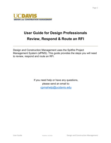
Is your Dipole a Tripole? Coax outside of braid acts as extension of transmitting antennaCoax cable has 3 conductors!Coax braid is actually 2 conductors :1 on the inside (normal RF signal), and1 on the outside (common modecurrent) that turns dipole into tripole!Goal is to reduce common modecurrent with a feed line choke to keepall RF on antenna.1% common mode braid current 2.75 watt radiation at 1500 watts input, or1.6 watts at 500 watts input or .7 watts at 100 watts input
Antenna feed line choke optionsDefinition: Feed line choke: 1:1 (50Ω to 50Ω). Impedance transformer: 1:1 or 1:1EVERY coax fed antenna needs a common mode choke at the antenna feed point!EVERY rotor control, remote antenna selector also needs a common mode choke!Feedline chokes (and impedance transformers) are made with several outputoptions dependent on antenna type and the output option determines whether it isan UNUN or BALUN: Prefix (output) Bal, Un, Suffix (input) UnUnuns #1 (verticals, end fed antennas)Ununs #2 (coax in/coax out)Baluns (beams, dipoles, loops, log periodics, etc.)Examples
UNUN #1 (coax input, /- output)Applications:Verticals, endfed antennas
UNUN #2 (coax in, coax out)Applications:Coax feedlinechoke or lineisolator
BALUN (coax in, balanced output)Application:Dipole, beam,loop, symmetricalantennasSo how do youchoose a feed linechoke for yourantenna coax?
Choosing a Feed Line ChokeCriteria to Consider Effective Frequency Range Adequate ChokingImpedance 500Ω Sufficient Power Rating Physical Size/weight Balun or unun output
Choose choking impedance 500Ωat frequency of useSuper Choker1-10 MHz 2K5KW PEP1K-6K Z3 poundsVerticalsAM/RTTYContestingLine isolator1-160 MHz 2K1.5KW PEP1K-6K Z1 poundAll coax linesOptionalground, staticbleeder
Feedline Chokes for all antennas1 MHzMedium choking Z (500-2000Ω) – 5KW PEP for RG213,only 5 beads needed over 30 MHz60 MHz
CUBE Chokes for all antennas Highest Choking (5-15K ohms) Power to 10KW PEP Use: Inline choke, beam, dipole, loop,vertical, 1:1 ladder line to coaxinterface (G5RV/ZS6BKW)Let’s Recap
RFI proof your transmissions recap Determine frequency range of RFI and Path Install AC/DC power and transceiver and amplifier RFI kits tosuppress RFI Install a feed line choke at the antenna feed point with enoughchoking impedance at the frequency of use in ALL antenna coaxlines of your station Install filters and chokes and retest for RFI suppression Consider additional filters and paths if RFI persistsIf you need helpCall Palomar Engineers or view specific solutions atPalomar-Engineers.comWhat about receiver noise?
Lower noise floor Higher SNR More DX!
Receiver RFI Noise (man made) SOURCES: plasma TV, Uverse/DSL, Cable Boxes, HVAC,appliances with variable speed motors –square wavegenerators, LED lights, wireless metering systems, wallwarts, switching power supplies, battery chargers,fluorescent lights, fish tank heaters, exercise equipment,computer “hash”, solar system inverters PATH: antenna coax braid, AC/DC power lines, phone/DSLline, computer to radio interconnects VICTIM: radio receiver – high noise level symptom SOLUTION: eliminate SOURCE, choke PATH, protectVICTIM – most “noise” from common mode current inAC/DC lines or coax braid acting as a receive antenna
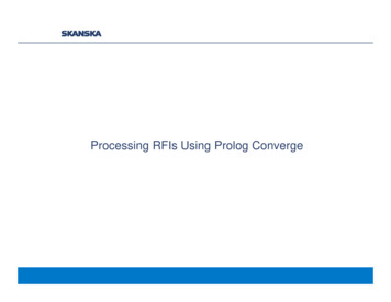
Coax Feed Line Noise Filters One of the best kept secrets in ham radio!!! Placed at RADIO END of coax feed line to suppress common modecurrent on coax braid between antenna feed point choke and radioChoke location
Dipole Antenna “Systems”
AC Line/DC Power FiltersPalomar F240 (1.4”ID/2.4”OD) Choke – 80-10meters, Z 2-5K range depending on frequency
Wall Wart RFI KitWall Wart switching DC power supplies that plug into the AC power line plug and provide DC power tolaptops, routers, battery chargers, cell phone chargers, etc are a known source of broadband RFIA simple ferrite ring filter on the DC power line can help suppress the RFI noise affecting the device orkeep the DC power cord from acting as an antenna and radiating RFI from the powered device.RFI Filter on DC CordEconomy 10 ring kit
Receiver RFI Noise Strategy Assess S-P-V for the RFI – You or someone else? PROTECT the VICTIM (Your receiver) Coax noise filters on antenna feed lines, chokes on rotor lines Chokes on AC/DC cords, Wall Warts – ring or snap on ferrites Chokes on radio-computer interconnect cables ELIMINATE/ISOLATE the SOURCE Choke AC/DC power to source, snap on ferrites for all I/O Call Palomar Engineers if you get stuck or need helpWhat about
OR
Neighbor’s RFI Strategy Choke RFI SOURCEHam’s Strategy is different
Ham’s Solution to Neighbor’s RFI Source (transmitter or antenna”) – Path – Victim Clean up your transmitter/shack first using techniquesalready discussed Assess Neighbor’s Problem Faulty device (device acting as receiver when notdesigned to be a radio receiver – e.g. Telephone, HDTV) Determine frequency of “transmitter” that is causing theproblem (may not be on all bands – may not be you!) Find the path (or paths) to the Victim (Receiver) Choose the RFI choke kit for the frequency and path Choke the path, protect the device (externally)!
Neighborhood RFI SolutionsRecommendation: Use RFI kits for specific problems, have neighbor purchaseand install – do not make mods to neighbors equipment! MOST problems areRFI picked up by AC power/phone lines so ferrite filters work well.Test Time – Win a prize!
Prize Question #1 What are 2 ways to increase thechoking impedance of a ferrite filterchoke?A)B)C)D)Use high resistance wire and multiple turns on beadUse multiple beads and dual core braided wireUse multiple beads in series with multiple turnsUse mix 31 and mix 77 beads in series with a single turn
Prize Question #2Mix 75/77 is used in which frequency rangeto suppress RFI common mode current? A) 1-300 MHz B) 200-2000 MHz C) .1-10 MHz D) 1-2000 MHz E) None of the above
Prize Question #3 What is one of the best kept secrets inham radio?a)Ladder line has more loss than coaxb) Coax wound chokes are effective from160-6 metersc) Coax noise filters reduce noise level inyour receiverd) All ferrite mixes work on all frequencies
Bonus Prize Question #4 Which company is your best sourcefor RFI solutions?
RFI Solutions ExpertsPalomar Engineers Website: www.Palomar-Engineers.comEmail: Sales@Palomar-Engineers.comPhone: 760-747-3343Bob Brehm, AK6R – Chief EngineerThis presentation available on the website.
Determine RFI interfering frequency & suspected Path Choose proper mix (31, 43, 61, 75/77) to suppress RFI fundamental frequency Choose Topology(slip, snap, ring) to fit the Path Install ferrites - retest for RFI suppression Consider additional ferrites or Paths if RFI persists