Transcription
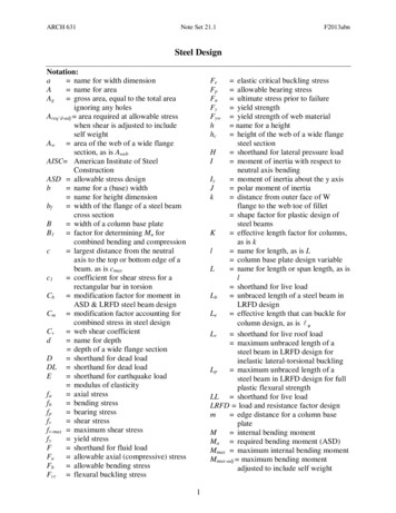
ARCH 631Note Set 21.1F2013abnSteel DesignNotation:a name for width dimensionA name for areaAg gross area, equal to the total areaignoring any holesAreq’d-adj area required at allowable stresswhen shear is adjusted to includeself weightAw area of the web of a wide flangesection, as is AwebAISC American Institute of SteelConstructionASD allowable stress designb name for a (base) width name for height dimensionbf width of the flange of a steel beamcross sectionB width of a column base plateB1 factor for determining Mu forcombined bending and compressionc largest distance from the neutralaxis to the top or bottom edge of abeam. as is cmaxc1 coefficient for shear stress for arectangular bar in torsionCb modification factor for moment inASD & LRFD steel beam designCm modification factor accounting forcombined stress in steel designCv web shear coefficientd name for depth depth of a wide flange sectionD shorthand for dead loadDL shorthand for dead loadE shorthand for earthquake load modulus of elasticityfa axial stressfb bending stressfp bearing stressfv shear stressfv-max maximum shear stressfy yield stressF shorthand for fluid loadFa allowable axial (compressive) stressFb allowable bending stressFcr flexural buckling stressFeFpFuFyFywhhc elastic critical buckling stress allowable bearing stress ultimate stress prior to failure yield strength yield strength of web material name for a height height of the web of a wide flangesteel sectionH shorthand for lateral pressure loadI moment of inertia with respect toneutral axis bendingIy moment of inertia about the y axisJ polar moment of inertiak distance from outer face of Wflange to the web toe of fillet shape factor for plastic design ofsteel beamsK effective length factor for columns,as is kl name for length, as is L column base plate design variableL name for length or span length, as isl shorthand for live loadLb unbraced length of a steel beam inLRFD designLe effective length that can buckle forcolumn design, as is eLr shorthand for live roof load maximum unbraced length of asteel beam in LRFD design forinelastic lateral-torsional bucklingLp maximum unbraced length of asteel beam in LRFD design for fullplastic flexural strengthLL shorthand for live loadLRFD load and resistance factor designm edge distance for a column baseplateM internal bending momentMa required bending moment (ASD)Mmax maximum internal bending momentMmax-adj maximum bending momentadjusted to include self weight1
ARCH 631Note Set 21.1Mn nominal flexure strength with thefull section at the yield stress forLRFD beam designMp internal bending moment when allfibers in a cross section reach theyield stressMu maximum moment from factoredloads for LRFD beam designMy internal bending moment when theextreme fibers in a cross sectionreach the yield stressn edge distance for a column baseplaten’ column base plate design valuen.a. shorthand for neutral axisN bearing length on a wide flangesteel section depth of a column base plateP name for load or axial force vectorPa required axial force (ASD)Pc available axial strengthPe1 Euler buckling strengthPr required axial forcePn nominal column load capacity inLRFD steel designPp nominal bearing capacity ofconcrete under base platePu factored column load calculatedfrom load factors in LRFD steeldesignr radius of gyrationR generic load quantity (force, shear,moment, etc.) for LRFD design shorthand for rain or ice loadRa required strength (ASD)Rn nominal value (capacity) to bemultiplied by in LRFD anddivided by the safety factor inASDRu factored design value for LRFDdesignS shorthand for snow load section modulusSreq’d section modulus required atallowable stressF2013abnSreq’d-adj section modulus required atallowable stress when moment isadjusted to include self weighttf thickness of flange of wide flangetmin minimum thickness of column baseplatetw thickness of web of wide flangeT torque (axial moment) shorthand for thermal loadV internal shear forceVa required shear (ASD)Vmax maximum internal shear forceVmax-adj maximum internal shear forceadjusted to include self weightVn nominal shear strength capacity forLRFD beam designVu maximum shear from factored loadsfor LRFD beam designwequivalent the equivalent distributed loadderived from the maximum bendingmomentwself wt name for distributed load from selfweight of memberW shorthand for wind loadX column base plate design valueZ plastic section modulus of a steelbeam actual actual beam deflection allowable allowable beam deflection limit allowable beam deflection limit max maximum beam deflection yield strain (no units) y b resistance factor resistance factor for bending forLRFD resistance factor for compressionfor LRFD resistance factor for shear forLRFD column base plate design value load factor in LRFD design pi (3.1415 radians or 180 ) radial distance safety factor for ASD c v 2
ARCH 631Note Set 21.1F2013abnSteel DesignStructural design standards for steel are establishedby the Manual of Steel Construction published bythe American Institute of Steel Construction, anduses Allowable Stress Design and Load andFactor Resistance Design. The 14th editioncombines both methods in one volume and providescommon requirements for analyses and design andrequires the application of the same set ofspecifications.MaterialsAmerican Society for Testing Materials (ASTM) is the organization responsible for material andother standards related to manufacturing. Materials meeting their standards are guaranteed tohave the published strength and material properties for a designation.A36 – carbon steel used for plates, anglesA572 – high strength low-alloy used for some beamsA992 – for building framing used for most beams(A572 Grade 60 has the same properties as A992)ASDRa RnFy 36 ksi, Fu 58 ksi, E 29,000 ksiFy 60 ksi, Fu 75 ksi, E 30,000 ksiFy 50 ksi, Fu 65 ksi, E 30,000 ksi whereRa required strength (dead or live; force, moment or stress)Rn nominal strength specified for ASD safety factorFactors of Safety are applied to the limit stresses for allowable stress values: 1.67 1.67 (nominal moment reduces) 1.5 or 1.67 2.00 (tabular nominal strength) 2.00bending (braced, Lb Lp)bending (unbraced, Lp Lb and Lb Lr)shear (beams)shear (bolts)shear (welds)-Lb is the unbraced length between bracing points, laterallyLp is the limiting laterally unbraced length for the limit state of yieldingLr is the limiting laterally unbraced length for the limit state of inelastic lateral-torsionalbuckling3
ARCH 631LRFDNote Set 21.1where Ru i RiRu RnwhereF2013abn resistance factor load factor for the type of loadR load (dead or live; force, moment or stress)Ru factored load (moment or stress)Rn nominal load (ultimate capacity; force, moment or stress)Nominal strength is defined as thecapacity of a structure or component to resist the effects of loads, as determined bycomputations using specified material strengths (such as yield strength, F y, or ultimatestrength, Fu) and dimensions and formulas derived from accepted principles of structuralmechanics or by field tests or laboratory tests of scaled models, allowing for modelingeffects and differences between laboratory and field conditionsFactored Load CombinationsThe design strength, Rn , of each structural element or structural assembly must equal or exceedthe design strength based on the ASCE-7 combinations of factored nominal loads:1.4D1.2D 1.6L 0.5(Lr or S or R)1.2D 1.6(Lr or S or R) (L or 0.5W)1.2D 1.0W L 0.5(Lr or S or R)1.2D 1.0E L 0.2S0.9D 1.0W0.9D 1.0ECriteria for Design of BeamsFb or Fn f b Allowable normal stress or normal stress from LRFD should not beexceeded:( M a M n / or M u b M n )Knowing M and Fb, the minimum section modulus fitting the limit is:Z req' d MaFy M S req' d Fb Besides strength, we also need to be concerned about serviceability. This involves things likelimiting deflections & cracking, controlling noise and vibrations, preventing excessivesettlements of foundations and durability. When we know about a beam section and its material,we can determine beam deformations.4McI
ARCH 631Note Set 21.1F2013abnDetermining Maximum Bending MomentDrawing V and M diagrams will show us the maximum values for design. Computerapplications are very helpful.Determining Maximum Bending StressFor a prismatic member (constant cross section), the maximum normal stress will occur at themaximum moment.For a non-prismatic member, the stress varies with the cross section AND the moment.DeflectionsElastic curve equations can be found in handbooks, textbooks, design manuals, etc.Computerprograms can be used as well.Elastic curve equations can be superpositioned ONLY if the stresses are in the elastic range.The deflected shape is roughly the same shape flipped as the bending moment diagram but isconstrained by supports and geometry.Allowable Deflection LimitsAll building codes and design codes limit deflection for beam types and damage that couldhappen based on service condition and severity.L actual allowable UseLL onlyRoof beams:IndustrialL/180Commercialplaster ceilingL/240no plasterL/360Floor beams:Ordinary UsageL/360Roof or floor (damageable elements)valueDL LLL/120L/180L/240L/240L/480Lateral BucklingWith compression stresses in the top of a beam, a sudden “popping” or buckling can happeneven at low stresses. In order to prevent it, we need to brace it along the top, or laterally brace it,or provide a bigger Iy.5
ARCH 631Note Set 21.1F2013abnLocal Buckling in Steel I Beams– Web Crippling orFlange BucklingConcentrated forces on a steel beam can cause the web tobuckle (called web crippling). Web stiffeners under thebeam loads and bearing plates at the supports reduce thattendency. Web stiffeners also prevent the web fromshearing in plate girders.The maximum support load and interior load can be determined from:Pn (max end) ( 2.5k N )Fyw t wPn (interior) ( 5k N )Fyw t wwheretw thickness of the webN bearing lengthk dimension to fillet found in beam section tables 1.00 (LRFD) 1.50 (ASD)Beam Loads & Load TracingIn order to determine the loads on a beam (or girder, joist, column, frame, foundation.) we canstart at the top of a structure and determine the tributary area that a load acts over and the beamneeds to support. Loads come from material weights, people, and the environment. This area isassumed to be from half the distance to the next beam over to halfway to the next beam.The reactions must be supported by the next lower structural element ad infinitum, to the ground.LRFD Bending or FlexureFor determining the flexural design strength, b M n , for resistance to pure bending (no axialload) in most flexural members where the following conditions exist, a single calculation willsuffice: i Ri M u b M n 0.9Fy ZwhereMu maximum moment from factored loads b resistance factor for bending 0.96
ARCH 631Note Set 21.1F2013abnMn nominal moment (ultimate capacity)Fy yield strength of the steelZ plastic section modulusfPlastic Section Modulusfy 50ksiPlastic behavior is characterized by a yield point and anincrease in strain with no increase in stress.E1 y 0.001724Internal Moments and Plastic HingesPlastic hinges can develop when all of the material in a cross section sees the yield stress.Because all the material at that section can strain without any additional load, the membersegments on either side of the hinge can rotate, possibly causing instability.For a rectangular section:Elastic to fy:Ibh 2b 2c 2bc 2M y fy fy fy fyc6632Fully Plastic:M ult or M p bc 2 f y 3 M y2For a non-rectangular section and internal equilibrium at y, then.a. will not necessarily be at the centroid. The n.a. occurs wherethe Atension Acompression. The reactionsoccur at the centroids of the tensionand compression areas.Atension Acompression7
ARCH 631Note Set 21.1F2013abnInstability from Plastic Hinges:Shape Factor:The ratio of the plastic moment to the elastic moment at yield:k Mpk 3/2 for a rectanglek 1.1 for an I beamMyPlastic Section ModulusZ Mpfyandk ZSDesign for ShearVa Vn / or Vu vVnThe nominal shear strength is dependent on the cross section shape. Case 1: With a thick or stiffweb, the shear stress is resisted by the web of a wide flange shape (with the exception of ahandful of W’s). Case 2: When the web is not stiff for doubly symmetric shapes, singlysymmetric shapes (like channels) (excluding round high strength steel shapes), inelastic webbuckling occurs. When the web is very slender, elastic web buckling occurs, reducing thecapacity even more:Case 1) For h t w 2.24EFyVn 0.6Fyw Aw v 1.00 (LRFD) 1.50 (ASD)where h equals the clear distance between flanges less the fillet or cornerradius for rolled shapesVn nominal shear strengthFyw yield strength of the steel in the webAw twd area of the webCase 2) For h t w 2.24EFyVn 0.6Fyw AwCv v 0.9 (LRFD)where Cv is a reduction factor (1.0 or less by equation)8 1.67 (ASD)
ARCH 631Note Set 21.1F2013abnDesign for FlexureM a M n / or M u b M n b 0.90 (LRFD) 1.67 (ASD)The nominal flexural strength Mn is the lowest value obtained according to the limit states of1. yielding, limited at length L p 1.76ryE, where ry is the radius of gyration in yFy2. lateral-torsional buckling limited at length Lr3. flange local buckling4. web local bucklingBeam design charts show available moment, Mn/ and b M n , for unbraced length, Lb, of thecompression flange in one-foot increments from 1 to 50 ft. for values of the bending coefficientCb 1. For values of 1 Cb 2.3, the required flexural strength Mu can be reduced by dividing itby Cb. (Cb 1 when the bending moment at any point within an unbraced length is larger thanthat at both ends of the length. Cb of 1 is conservative and permitted to be used in any case.When the free end is unbraced in a cantilever or overhang, Cb 1. The full formula is providedbelow.)NOTE: the self weight is not included in determination of b M nCompact SectionsFor a laterally braced compact section (one for which the plastic moment can be reached beforelocal buckling) only the limit state of yielding is applicable. For unbraced compact beams andnon-compact tees and double angles, only the limit states of yielding and lateral-torsionalbuckling are applicable.bfhEE 0.38Compact sections meet the following criteria:and c 3.762t fFytwFywhere:bf flange width in inchestf flange thickness in inchesE modulus of elasticity in ksiFy minimum yield stress in ksihc height of the web in inchestw web thickness in inchesWith lateral-torsional buckling the nominal flexural strength is M n Cb M p ( M p 0.7 Fy S x Lb L p Mp) L L p r9
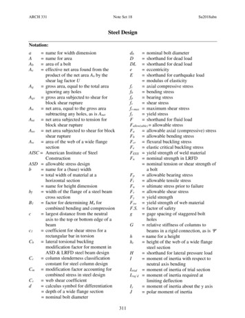
ARCH 631Note Set 21.1F2013abnwhere Cb is a modification factor for non-uniform moment diagrams where, when both endsof the beam segment are braced:12.5M maxCb 2.5M max 3M A 4M B 3M CMmax absolute value of the maximum moment in the unbraced beam segmentMA absolute value of the moment at the quarter point of the unbraced beam segmentMB absolute value of the moment at the center point of the unbraced beam segmentMC absolute value of the moment at the three quarter point of the unbraced beamsegment length.Available Flexural Strength PlotsPlots of the available moment for the unbraced length for wide flange sections are useful to findsections to satisfy the design criteria of M a M n / or M u b M n . The maximum momentthat can be applied on a beam (taking self weight into account), Ma or Mu, can be plotted againstthe unbraced length, Lb. The limit Lp is indicated by a solid dot ( ), while Lr is indicated by anopen dot ( ). Solid lines indicate the most economical, while dashed lines indicate there is alighter section that could be used. Cb, which is a modification factor for non-zero moments atthe ends, is 1 for simply supported beams (0 moments at the ends). (see figure)10
ARCH 631Note Set 21.1F2013abnDesign ProcedureThe intent is to find the most light weight member (which is economical) satisfying the sectionmodulus size.1. Determine the unbraced length to choose the limit state (yielding, lateral torsional bucklingor more extreme) and the factor of safety and limiting moments. Determine the material.2. Draw V & M, finding Vmax and Mmax.for unfactored loads (ASD, Va & Ma) or from factoredloads (LRFD, Vu & Mu)3. Calculate Sreq’d or Z when yielding is the limit state. This step is equivalent to determiningMMMMuif f b max Fb , S req' d max max and Z to meet the design criteria thatFyFbS b Fb M a M n / or M u b M nIf the limit state is something other than yielding,determine the nominal moment, Mn, or use plots ofavailable moment to unbraced length, Lb.4. For steel: use the section charts to find a trial S or Z andremember that the beam self weight (the second numberin the section designation) will increase Sreq’d. or Z Thedesign charts show the lightest section within a groupingof similar S’s or Z’s.****Determine the “updated” Vmax and Mmax including the beam self weight, and verify that theupdated Sreq’d has been met.******5. Evaluate horizontal shear using Vmax. This step is equivalent to determining if f v Fv issatisfied to meet the design criteria that Va Vn / or Vu vVnFor I beams:Others:3VVV 2 A Aweb t w dVQ Ibf v max f v maxVn 0.6Fyw Awor Vn 0.6Fyw AwCv6. Provide adequate bearing area at supports. This step is equivalent to determining ifis satisfied to meet the design criteria that Pa Pn / or Pu Pn7. Evaluate shear due to torsionfv fp P FpAT Tor Fv (circular section or rectangular)Jc1 ab 28. Evaluate the deflection to determine if max LL LL allowed and/or max Total Tota lallowed**** note: when calculated limit, Irequired can be found with:and Sreq’d will be satisfied for similar self weight *****11I req' d too bigI trial lim it
ARCH 631Note Set 21.1F2013abnFOR ANY EVALUATION:Redesign (with a new section) at any point that a stress or serviceability criteria isNOT satisfied and re-evaluate each condition until it is satisfactory.Load Tables for Uniformly Loaded Joists & BeamsTables exist for the common loading situation of uniformly distributed load. The tables eitherprovide the safe distributed load based on bending and deflection limits, they give the allowablespan for specific live and dead loads including live load deflection limits.wequivalentL2If the load is not uniform, an equivalent uniform load can be calculatedM max 8from the maximum moment equation:If the deflection limit is less, the design live load tocheck against allowable must be increased, ex. L / 360 wadjusted wll have L / 400 table limitwantedCriteria for Design of ColumnsIf we know the loads, we can select a section that is adequate for strength & buckling.If we know the length, we can find the limiting load satisfying strength & buckling.Design for CompressionAmerican Institute of Steel Construction(AISC) Manual 14th ed:Pa Pn / or Pu c PnwherePu i Pi is a load factorP is a load type is a resistance factorPn is the nominal load capacity (strength) 0.90 (LRFD) 1.67 (ASD)For compression Pn Fcr Agwhere :Ag is the cross section area and Fcr is the flexural buckling stress12
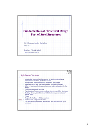
ARCH 631Note Set 21.1F2013abnThe flexural buckling stress, Fcr, is determined as follows:whenKLEor ( Fe 0.44Fy ): 4.71rFyFy Fcr 0.658 Fe Fy whenKLEor ( Fe 0.44Fy ): 4.71rFyFcr 0.877 Fewhere Fe is the elastic critical buckling stress:Fe 2E KL r 2Design AidsSample AISC Table for Available Strength in AxialCompressionTables exist for the value of the flexural buckling stress based on slenderness ratio. In addition,tables are provided in the AISC Manual for Available Strength in Axial Compression based onthe effective length with respect to least radius of gyration, ry. If the critical effective length isabout the largest radius of gyration, rx, it can be turned into an effective length about the y axisby dividing by the fraction rx/ry.13
ARCH 631Note Set 21.1F2013abnProcedure for Analysis1. Calculate KL/r for each axis (if necessary). The largest will govern the buckling load.2. Find Fcr as a function of KL/r from the appropriate equation (above) or table.3. Compute Pn Fcr Agor alternatively compute fc Pa/A or Pu/A4. Is the design satisfactory?Is Pa Pn/ or Pu cPn? yes, it is; no, it is no goodor Is fc Fcr/ or cFcr? yes, it is; no, it is no goodProcedure for Design1. Guess a size by picking a section.2. Calculate KL/r for each axis (if necessary). The largest will govern the buckling load.3. Find Fcr as a function of KL/r from appropriate equation (above) or table.4. Compute Pn Fcr Agor alternatively compute fc Pa/A or Pu/A5. Is the design satisfactory?Is P Pn/ or Pu cPn? yes, it is; no, pick a bigger section and go back to step 2.Is fc Fcr/ or cFcr? yes, it is; no, pick a bigger section and go back to step 2.6. Check design efficiency by calculating percentage of stress used: PaP 100% or u 100%Pn c Pn If value is between 90-100%, it is efficient.If values is less than 90%, pick a smaller section and go back to step 2.Columns with Bending (Beam-Columns)In order to design an adequate section for allowable stress, we have to start somewhere:1. Make assumptions about the limiting stress from:- buckling- axial stress- combined stress1. See if we can find values for r or A or Z (S for ASD)2. Pick a trial section based on if we think r or A is going to govern the section size.14
ARCH 631Note Set 21.1F2013abn3. Analyze the stresses and compare to allowable using the allowable stress method orinteraction formula for eccentric columns.4. Did the section pass the stress test?- If not, do you increase r or A or S?- If so, is the difference really big so that you could decrease r or A or S to make itmore efficient (economical)?5. Change the section choice and go back to step 4. Repeat until the section meets thestress criteria.Design for Combined Compression and Flexure:The interaction of compression and bending are included in the form for two conditions based onthe size of the required axial force to the available axial strength. This is notated as Pr (either Pfrom ASD or Pu from LRFD) for the axial force being supported, and Pc (either Pn/ for ASD or cPn for LRFD). The increased bending moment due to the P- effect must be determined andused as the moment to resist.Pr 0.2 :ForPc My P8 Mx 1.0PnM ny 9 M nx (ASD)Pr 0.2 :ForPcP2 PnM uy Pu8 M ux 1.0 c Pn 9 b M nx b M ny (LRFD) MxMy 1.0MMnxny (ASD) M uxM uy Pu 1.0 2 c Pn b M nx b M ny (LRFD)where:for compressionfor bending c 0.90 (LRFD) b 0.90 (LRFD) 1.67 (ASD) 1.67 (ASD)For a braced condition, the moment magnification factor B1 is determined by B1 Cm 1.01 ( Pu Pe1 )where Cm is a modification factor accounting for end conditionsWhen not subject to transverse loading between supports in plane of bending: 0.6 – 0.4 (M1/M2) where M1 and M2 are the end moments and M1 M2. M1/M2 ispositive when the member is bent in reverse curvature (same direction), negativewhen bent in single curvature.When there is transverse loading between the two ends of a member: 0.85, members with restrained (fixed) ends 2 EA 1.00, members with unrestrained endsPe1 Pe1 Euler buckling strength15 Kl r 2
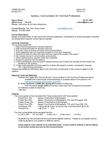
ARCH 631Note Set 21.1F2013abnCriteria for Design of Connections and Tension MembersRefer to the specific note set.Criteria for Design of Column Base PlatesColumn base plates are designed for bearing on the concrete(concrete capacity) and flexure because the column “punches”down the plate and it could bend upward near the edges of thecolumn (shown as 0.8bf and 0.95d). The plate dimensions are Band N and are preferably in full inches with thicknesses inmultiples of 1/8 inches.LRFD minimum thickness: t min l2 Pu0.9 Fy BNwhere l is the larger of m, n and n m n N 0.95d2n db f 4B 0.8b f22 X(1 1 X ) 1where X depends on the concrete bearing capacity of c Pp, with c 0.65 and Pp 0.85f’cAX 4db f(d b f )2 4db fPuPu 2 c Pp (d b f ) c (0.85 f c ) BN1600
ARCH 631Note Set 21.1F2013abnBeam Design Flow ChartCollect data: L, , , limits; find beam chartsfor load cases and actual equationsASDCollect data: Fy, Fu, andsafety factors Collect data: load factors, Fy,Fu, and equations for shearcapacity with VFind Vmax & Mmax fromconstructing diagrams orusing beam chart formulasFind Vu & Mu fromconstructing diagrams orusing beam chart formulaswith the factored loadsFind Zreq’d and pick a sectionfrom a table with Zx greater orequal to Zreq’dPick a steel section from a chart having bMn Mu for the known unbraced lengthORfind Zreq’d and pick a section from a tablewith Zx greater or equal to Zreq’dDetermine self wt (last number inname) or calculate self wt. using Afound. Find Mmax-adj & Vmax-adj.NoLRFDAllowable Stress orLRFD Design?Determine self wt (last number inname) or calculate self wt. using Afound. Factor with D.Find Mu-max-adj & Vu-max-adj.Calculate Sreq’d-adj using Mmax-adj.Is Sx(picked) Sreq’d-adj?YesIs Vmax-adj (0.6FywAw)/ .?Nopick a new section with alarger web areaYesIs Mu bMnIs Vu v(0.6FywAw)Calculate max (no load factors!)using superpositioning and beamchart equations with the Ix for thesectionis max limits?This may be both the limit for live loaddeflection and total load deflection.)Yes(DONE)17YesI req' d NoNopick a sectionwith a largerweb area too bigI trial lim itNopick a section with a larger I x
ARCH 631Note Set 21.1F2013abnListing of W shapes in Descending Order of Zx for Beam DesignZx – US(in.3)Ix – US(in.4)SectionIx – SI(106mm.4)Zx – SI(103mm.3)Zx – US(in.3)289Ix – US(in.4)3100SectionW24X104Ix – SI(106mm.4)1290Zx – 02460W18X13010204750(continued)18
ARCH 631Note Set 21.1F2013abnListing of W Shapes in Descending order of Zx for Beam Design (Continued)Zx – US(in.3)Ix – US(in.4)SectionIx – SI(106mm.4)Zx – SI(103mm.3)Zx – US(in.3)Ix – US(in.4)SectionIx – SI(106mm.4)Zx – 730.8W8X1012.814519
ARCH 631Note Set 21.1F2013abnAvailable Critical Stress, cFcr, for Compression Members, ksi (Fy 36 ksi and c 262728293031323334353637383940 c 758596061626364656667686
Steel Design Structural design standards for steel are established by the Manual of Steel Construction published by the American Institute of Steel Construction, and uses Allowable Stress Design and Load and Factor Resistance Design. The 14th edition combines both methods in one volume and provides common requirements for analyses and design and