Transcription
MOISTURE MOVEMENT IN WALLSIN A WARM HUMID CLIMATEA. TenWoldeH.T. Mei, Ph.D.ABSTRACTMost research on condensation of moisture in exterior wood-frame walls has focused on moistureproblems in walls in cold winter climates even though air-conditioned buildings in warm, humidclimates also have potential for moisture damage. To investigate moisture movement in wallsin a warm, humid climate, a test building was erected on the campus of Lamar University,Beaumont, TX. This building holds nine instrumented wall panels of different construction.The panels are all installed on the south side of the building.All wall cavities were insulated with 3-1/2-in (89-mm) fiberglass batt. Hardboard sidingwas installed on all wall panels over either wood fiberboard sheathing or aluminum-faced moldedexpanded polystyrene sheathing. A polyethylene sheet was installed between the fiberboardsheathing and siding in one panel. Another panel contained a ventilated airspace between thefiberboard sheathing and siding. Two panels contained a polyethylene vapor retarder on theroom side of the insulated cavity. Temperatures and humidity conditions in the panels wererecorded from early spring until late fall in 1984.In one panel with fiberboard sheathing, moisture condensed on the polyethylene vaporretarder located on the room side during the afternoon but reevaporated during the followingnight. Other wall panels showed no evidence of condensation. Walls without the aluminum orpolyethylene between siding and sheathing showed slightly higher humidity in the cavity, butthe siding of those panels was generally drier and experienced less fluctuation in moistureconditions than the siding installed over the aluminum-faced polystyrene or the polyethylenesheet. The ventilated airspace had little effect on moisture conditions in the siding or therest of the wall but should be further evaluated with sheathing materials other than fiberboard. Taping of the joints between sheathing panels had no discernible effect. Testing ofseveral panels of different dimensions, but with the same design and materials, showed onlyminor differences in moisture levels.INTRODUCTIONRecent changes in wood-frame construction practices and the use of new building materials haverenewed interest in the condensation of moisture in walls Although evidence of condensationdamage in walls is scarce, the possibility of extensive concealed structural damage has causedwidespread concern.Most research on moisture movement and condensation in walls has focused on winter conditions. Burch et al. (1978) detected moisture accumulation in walls subjected to a constanttemperature and humidity gradient in the laboratory. In field exposure tests, Sherwood (1983)found that moisture condensed during periods of cold weather but evaporated rapidly whenthe outdoor temperature rose. Surveys of walls during winter and early spring in thePacific Northwest (Tsongas et al. 1980) showed fewer moisture problems from condensation thanA. TenWolde, Physicist, USDA Forest Service, Forest Products Laboratory.H. T. Mei, Professor of Mechanical Engineering, Lamar University.570
initially expected. Although the literature indicates that winter condensation in walls isclosely related to indoor humidity levels and the presence and integrity of an air-vaporretarder, many questions remain unanswered.In comparison, even less is known about moisture in the walls of air-conditioned buildingsin warm, humid climates. In theory, potential for moisture damage is greater in such aclimate, but the evidence of damage from condensation in walls is inconclusive. Verrall (1962)reported some cases of paint failure and mold but no cases of decay. Duff (1972) did not detect significant moisture accumulation in wood-frame walls of an air-conditioned building inAthens, GA. Sherwood (1985) did find evidence of periods of condensation in several walls inan air-conditioned test building in Gulfport, MS, but those walls dried out in the fall and nodamage was visible. He also noted that walls with permeable hygroscopic sheathing materialsfacing south had higher moisture levels than the same type of walls facing north. It appearedthat direct sun striking the wall drove moisture out of the sheathing and into the wall cavity.Condensation problems in warm, humid climates are distinctly different from those incold-winter climates. During warm, humid days, water vapor moves into the wall from outsideto inside and may condense on colder surfaces. Moisture condenses at temperatures thatfavor growth of decay organisms. Whereas indoor humidity control by ventilation often offersan effective way to prevent condensation in walls during the winter, especially in cold-winterclimates, outdoor humidity during the summer cannot be controlled. Design solutions, such asplacement of an effective vapor retarder, remain the only options. Mei and Woolrich (1963)investigated the proper placement of vapor retarders in a humid climate, but their study waslimited in scope and did not lead to practical installation guidelines.OBJECTIVESTo address some of the many remaining questions, Lamar University, Beaumont, TX, and theForest Products Laboratory, Madison, WI, conducted a cooperative field-exposure study in awarm, ,humid climate. An air-conditioned test building was erected on the Lamar Universitycampus and wood-frame walls of different designs were monitored during spring, summer, andearly fall of 1984.Spe'6ific objectives of the study were:1. Establish what combination of wall design and weather conditions leads to condensationand moisture accumulation. Specifically, the influence of sheathing type and of the presenceand placement of vapor retarders was investigated.2 , Determine Whether currently available moisture analysis methods for walls, such asthe Kieper and MOISTWALL procedures (TenWolde 1983, 1985), adequately predict condensation.3.' Determine whether the size of wall panels for field tests can be reduced so that morevanels cal). be 'tested simultaneously.4. Determine whether sealing the joints between sheathing panels has a significant effecton 'moiijturi!"""conditions in the wall.5 Determine whether a ventilated airspace between siding and sheathing affects moistureconditions '.in the wall.6.'Determine what Can be done to prevent moisture problems in walls in warm, humidclimates Although.itis impossible to answer these complex questions conclusively with one fieldstudy over one .sUlIIIIIet season, we believed that carefully selected designs could yield qualitative answers.,571
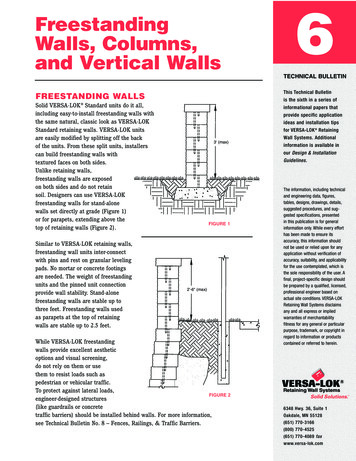
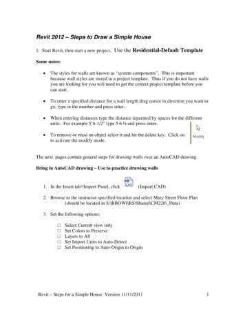
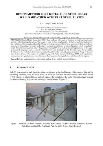
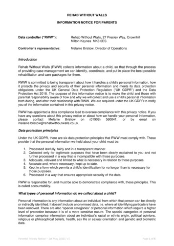
EXPERIMENTAL DESIGN AND PROCEDURESTest BuildingThe test building (Figure 1) is located on the campus of Lamar University, Beaumont, TX.Beaumont has a Gulf Coast climate with summer temperatures ranging from 68 to 95 F (20 to 35 C)combined with extremely high relative humidity (RR). Winter temperatures average around 54 F(12 C).The building is about 25 ft long by 8 ft wide (7.6 by 2.4 m) and contains nine instrumented wall panels of varying size and construction, all facing south. The north wall alsocontains several panels, but these were not instrumented or monitored. South and north wallsare framed with nominal 2 by 6 studs. The I-ft- (305-mm) wide wall sections between testpanels are sheathed with 7/8-in- (22-mm) thick molded expanded polystyrene boards with aluminumfacing on one side and have a total approximate R-value of 22. East- and west-facing wallshave nominal 2 by 4 framing with the same sheathing (total R-14). The ceiling is insulated toR-19 and the floor to R-l1. A detailed description of the test building can be found in aprevious paper (Mei and Yang 1985).Test Wan PanelsThe wood-frame test wall panels were all framed with nominal 2 by 4 studs and insulatedwith 3-1/2 in of fiberglass batt insulation. A 3lB-in hardboard siding covered all panels.Wood fiberboard (1/2 in, 13 mm) and 7/8-in molded expanded polystyrene foamboard were the twosheathing materials used. (Mei and Yang [1985] erroneously reported 1 in fiberboard and 1 inpolystyrene.) The foamboard had an aluminum facing that was installed towards the siding. Onthe inside, l/2-in (13-mm) unpainted gypsumboard was installed. One panel (S4) contained anairspace between the siding and sheathing. In some panels, the kraft paper backing wasremoved from the insulation before installation. The inside surfaces of the nominal 2 by 4framing for the panels were painted with two coats of water seal and paint to prevent lateralmovement of water vapor. The panels were installed with a gasket between the edge of the paneland the edge of the opening to prevent air leakage. Construction and design of the panels issummarized in Table 1. The wall panels were of three different sizes: 3 by 7 ft (0.92 by2.13 m), 1.5 by 7 ft (0.46 by 2.13 m), and 1.5 by 3.5 ft (0.46 by 1.07 m). The sheathing inthe two 3- by 7-ft wall panels (Sl and S2) consisted of two 1.5- by 7-ft (0.46- by 2.13-m)polystyrene boards with a joint over an extra nominal 2 by 4 stud in the center of the panel.In wall panel 82 this joint was taped with aluminum tape.On August 6, 1984, partway through the experiment, changes were made to three panels. Weadded a polyethylene vapor retarder to Sl and S9 between the insulation and the gypsumboard,and we drilled six l/4-in- (6-mm) diameter vent holes through the siding of panel S4--three at1 in (25 mm) from the top and three at 1 in (25 mm) from the bottom.Environmental ConditionsOutdoor and indoor temperature and RH were measured and recorded. The indoor temperaturewas maintained between 68 F (20 C) and 73 F (23 C) with RH between 50% and 60%. It was necessary to install a dehumidifier at the beginning of May to maintain this range in humidity.InstrumentationOutdoor and indoor air temperatures and humidities were measured separately.measured with a capacitance-type meter.Humidity wasTemperatures and humidities in the panels were measured with thermocouples and humidityThe humidity sensors were wood electric resistance sensors, similar to those elaS()rSby Duff (1966). Mei and Yang (1985) describe this modified sensor in their paperAppendix A. Two thermocouple/humidity sensor pairs were located on each surface of eachone pair about 2 ft (0.6 m) from the top and the other pair 2 ft (0.6 m) from the(Figure 2). Additional pairs of thermocouples and humidity sensors were placed in the572
insulation 1.5 and 2.5 in (38 and 64 mm) from the gypsumboard both near top and bottom of thepanel. The smaller panels 85 and S6 contained only one series of sensors placed at midheight.The total of 120 humidity sensors provided input to four amplifiers via four rotary switches.On August 6, 1984, partway through the experiment, polyethylene vapor retarders were addedto panels Sl and S9. Additional pairs of sensors were placed on the vapor retarders at the topand bottom.The electronic equipment was calibrated on site by substituting known electric resistances for the sensors. The relationship between electric resistance of the sensor and RH wasdetermined for a sample of ten sensors. This calibration showed that the effective range ofthe humidity measuring equipment was approximately from 60% to 100% RH. The sensors werecalibrated at 70 and 90 F (21 and 32 C). In this temperature range there was no systematiceffect of temperature, and RH readings were therefore not corrected for temperature duringdata analysis.Uncertainty for individual readings is in the range of 10% RH, based on doubling thestandard deviation in the calibration data. Individually calibrating each of the 120 sensorsbefore insertion in the panels would be more accurate but impractical.Data CollectionData were collected from April 1 through November 30, 1984, usually twice a day, duringmid-morning and mid-afternoon. On many days extra readings were taken late in the evening.For the two days (August 7 and 8) immediately following the modifications of panels Sl, S4,and S9, data were recorded hourly. Collection cycles of six to eight readings per day wererepeated between August 19 and 25 and throughout September.Data AnalysisWith the assumption that the humidity sensors were always in moisture equilibrium with thesurrounding air, we converted millivolt output to RH, using the results from the calibrationtests. RH indicates how close to moisture saturation the various materials were. An RH of100% indicates condensation. We defined sustained condensation as 100% RH over a period of24 hours or longer. If condensation occurred for shorter periods and the RH returned to previous levels we labeled it cyclical or transient.To compare measured results with analytical predictions we used the MOISTWALL analysismethod (TenWolde 1983, 1985). MOISTWALL is a computerized moisture analysis method for walls,based on steady-state one-dimensional vapor diffusion theory. As input parameters we usedpublished data for thermal resistance and permeance of the various materials. Temperatures andhumidities were chosen close to the measured values in August.RESULTSThe measured outdoor conditions are displayed in Figure 3. The temperature varied between68 to 95 F (20 to 35 C) in the summer months with RH averaging between 60% and 80%. In lateOctober and November temperatures dropped and ranged from 55 to 77 F (13 to 25 C). Measuredindoor conditions are shown in Figure 4.CondensationOnly panel 89 experienced some cyclical condensation on the vapor retarder immediatelyafter it was installed. The newly installed sensor on the polyethylene immediately began toregister cyclical high RH conditions (Figure 5). The sensor in the adjacent insulation,located 1.5 in (38 mm) from the vapor retarder, also shows an increase in RH in the insulationimmediately following the change. The condensation on the polyethylene was purely cyclicaland there was no long-term moisture accumulation during the period of September 15 throughNovember 30 (Figure 6). 3
Cyclical condensation was detected only in panel S9, the only wall panel with a permeable,hygroscopic sheathing (fiberboard) and a polyethylene vapor retarder on the room side of thewall cavity. All other panels had either a foil-faced sheathing, an outside polyethylene vaporretarder, or no effective inside vapor retarder and did not experience any condensation.The condensation cycle in panel S9 was entirely caused by solar radiation warming thesiding and sheathing and driving part of the moisture stored in the siding and sheathing intothe wall cavity. This moisture eventually condensed on the polyethylene when the humidity inthe cavity had risen sufficiently. At night, this relatively small quantity of condensedmoisture evaporated and was mostly readsorbed in the sheathing and siding, while the exteriorsurface of the siding absorbed moisture from the outside air. The next morning, the cyclerepeated.The events during a condensation cycle in panel S9 are illustrated in Figure 7. OnAugust 7 at 9:20 a.m. the outside surface of the siding showed a high RH but all other sensorsindicated an RH of less than 65%. The sun had already raised the surface temperature of thesiding to 83 F (28 C), 3 F (2 e) above the air temperature. By late afternoon (4:55 p.m.), thesituation had drastically changed. The sun had dried out the siding, which was at 95 to 98 F(35 to 37 e) or 15 to 18 F (8 to 10 0 e) above air temperature, but the sensor on the lower sideof the polyethylene vapor retarder showed condensation. The temperature of the sheathing hadreached 93 to 98 F. At midnight the vapor retarder was beginning to dry off and the siding hadbegun to readsorb moisture as demonstrated by elevated humidities between 70 and 85%. Bothsiding and sheathing had cooled to about 80 F (27 e). These trends continued during the night.At 4:10 a.m., sheathing and siding had cooled approximately to outside air temperature and thevapor retarder was almost dry. By 6:20 a.m., the polyethylene was dry (62% RH) and much ofthe rest of the wall was below 60% RH. The siding was just beginning to dry out as well. At9:20 a.m., the condensation cycle was about to start again; the siding continued to warm up,driving moisture into sheathing and wall cavity. The humidity at the vapor retarder once againstarted to rise.Vapor RetardersThe fiberglass batts in panels Sl (before August 6), S2, S4, and S8 all had kraft paperThis resulted in somewhat higher humidities in the cavities of those panels andslightly drier gypsumboard, compared to panels without the kraft paper. Apparently thekraft paper is a moderately effective vapor retarder. Unfortunately we were unable to detectif condensation occurred on the kraft paper because there were no humidity sensors in thatlocation. For the remainder of this discussion the term "vapor retarder" will refer to moreeffective vapor retarders such as aluminum and polyethylene foil, unless specifically statedotherwise.backing.The results do not clearly show a need for a vapor retarder on the outside of the wall.The cavities of all the panels with such a vapor retarder (panels Sl, S2, S3, S5, S6, and S7)were somewhat drier than the other panels, but the difference was very small. However, when apolyethylene inside vapor retarder was present (Sl and S9), the outside vapor retarder (Sl)effectively prevented condensation (Figures 6 and 8). Figure 8 shows that, although occasionalpeaks of 85% to 90% RH were reached at the vapor retarder in SI, the wall stayed essentiallydry. This confirms recent data published by Sherwood (1985) who also did not find any moistureaccumulation in walls with double (inside and outside) vapor retarders exposed to a hot, humidsummer climate.Comparison With Analytical Model ResultsAnalysis of all panels with the MOISTWALL method predicted no condensation in any of thepanels. MOISTWALL is limited to steady-state vapor diffusion and does not consider hygroscopicity or transient phenomena. It was, therefore, unable to predict the condensation cyclesin panel S9, but it correctly indicated that no long-term moisture accumulation would takeplace. Predictions of RH at various locations in the walls were generally inaccurate becauseof the influence of hygroscopic materials, thermal storage, and transient moisture and heatflows, none of which are considered in the MOISTWALL analysis.574
Taping of Joints in 8heathingTaping of the joints between sheathing panels had no measurable effect. Relative humidityin the wall with a taped joint (82) was approximately the same as in panel 81) which was nottaped. After August 6, when the polyethylene vapor retarder was installed in 81, RH in thecavity of 81 gradually increased to levels slightly higher than those in 82.Ventilation between Sheathing and SidingThe test panel with the 3j4-in (19 mm) airspace between the fiberboard sheathing and thesiding (84) showed little difference in RH from the comparable panel without the airspace (88).Drilling the ventilation holes through the siding made no difference. Both walls were essentially dry, including the siding. However, ventilating the back of the siding may well havemore beneficial effects with different sheathing types or different climates, as we willdiscuss later.Panel SizeThe behavior of the smaller panels (85 and 86) was very similar to that of the largerpanel with the same construction (87).However, all three walls were very dry, and many ofthe sensors did not register a signal because of their limited range (60 to 100% RH).It maybe expedient to reduce the size of test panels for field tests, which would enable simultaneoustesting of more different panels, but more evidence is needed before this can be concludedwith certainty.InsulationThe results show that the fiberglass insulation stayed dry in all panels. This was trueeven in panel 89 during condensation cycles. Even while water vapor was condensing on thepolyethylene, the sensors in the insulation 1.5 in (38 mm) away registered less than 70% RH(Figure 7).The highest RH measured at that location during the entire test period was 76%.The humidity in the insulation of all other panels was well below that. This confirms previoussimilar findings, as well as demonstrates the accuracy of theoretical calculations, showingthat permeable nonhygroscopic insulation in wall cavities tends to remain dry (TenWolde 1983,1985).8idingAlthough we did not intend to study moisture conditions in the siding specifically, theresults showed an interesting trend: RH at the back of siding applied over an outside vaporretarder (i.e., polyethylene or aluminum foil) was generally 5 to 10% higher than that ofsiding applied over fiberboard.Figure 9 shows this difference between siding over foil-facedpolystyrene (panel 87) and siding over fiberboard (panel 88). 8iding over a polyethylene vaporretarder (panel 83) behaved identically to siding over foil-faced polystyrene (panels 81, 82,85, S6, and 87).Comparison of Figures 7 and 10 illustrates the difference between panel 89, which hasfiberboard sheathing, and panel 81, which has foil-faced polystyrene.The situation in bothpanels was approximately the same at 9:20 a.m. on August 7. At 4:55 p.m., moisture near theoutside surface of the siding had been driven inwards, but in panel 81 this moisture had beentrapped by the aluminum foil on the polystyrene, while in panel 89 (Figure 7) it migrated intoand through the fiberboard. This resulted in much lower humidity at the back of the siding ofpanel 89. At midnight the siding had begun to readsorb moisture and continued to do so throughthe rest of the night. At 9:20 a.m. the next morning, the sun has started to drive moisture tothe back of the siding. Throughout the entire 24-hour period, the humidity at the back of thesiding of panel 81 was higher than in panel S9.This effect of an outside vapor retarder on the siding is by no means surprising or evenalarming. The moisture content of the siding of all panels remained well within acceptablelimits throughout the study period. However, under more severe conditions of humidity ormoisture or with other types of siding, ability of the siding to dry out towards the insidemay well make the difference between acceptable and problematic performance of the siding.575
DISCUSSIONAlthough this study has provided some answers, many questions remain partially or completelyunanswered. The results showed good performance of walls with exterior vapor retarders duringthe summer and fall, but we did not gather sufficient data to guarantee good performance duringthe winter.The merits of ventilating the back of the siding also remain unclear. Although theresults show no effect, this may be caused by the capacity of the fiberboard sheathing toabsorb and transmit moisture. With other types of sheathing, especially foil-faced foamsheathing, the results might well have been different. This issue needs more research.The influence of panel size is also not yet resolved. The results show little difference in behavior of larger and smaller panels. However, the limitations of the instrumentation and the lack of data from similar experiments by others prevent us from drawing a moregeneral conclusion about the influence of panel size.Although the building and instrumentation were finished by February 1984 and data collection was started, no useful data could be collected until April because it took the wall panelsconsiderable time to equilibrate with their environment. Those involved in similar tests inthe future should allow for a one- to two-month adjustment period, especially if moisture andtemperature gradients across the wall are relatively small.We have not discussed the influence of indoor temperature. Of course, lower indoor temperatures during the summer increase the potential for condensation and could well have led tomoisture accumulation in panel 89. However, indoor temperatures were already maintained belowthe more typical setting of 78 F. The cyclical condensation that occurred in panel 89 is mostlikely also influenced by factors other than indoor temperature and the sun. Outdoor temperature and humidity during the night should have an effect on the amount of moisture absorbedin the siding, which in turn affects the amount of moisture driven into the wall cavity thenext day.Walls with an outside vapor retarder as well as walls without any vapor retarders remaineddry throughout the study period. However, the walls without any vapor retarder transferredmore moisture, providing greater latent load for the air-conditioning equipment. We are unableto estimate the energy savings resulting from a vapor retarder, although we suspect that it issmall compared to the latent load from ventilation air.CONCLUSIONFor outdoor and indoor temperature and RH- conditions similar to those described earlier in thispaper (Figures 3 and 4), we can draw the following conclusions:1. Walls with outside polyethylene or aluminum foil vapor retarders or without any vaporretarders either inside or outside remain dry.2. An interior polyethylene vapor retarder and fiberboard sheathing can result incyclical condensation on the vapor retarder. Although it may not produce long-term moistureaccumulation, this indicates that in a warm, humid climate, an interior vapor retarder isundesirable unless an exterior vapor retarder is installed as well.3. A steady-state diffusion analysis method can correctly predict seasonal behavior butis unable to quantitatively predict specific conditions in the panels. Models incorporatinghygroscopicity and transient behavior are needed for more accurate predictions.4. Direct and indirect radiation from the sun has a major influence on humidity conditions in south-facing walls with hygroscopic sheathing.5. Sealing joints between sheathing panels probably has little effect on humidity conditions in the wall.6. Although a ventilated airspace between siding and sheathing had no effect on performance, more information is needed to investigate the effect with different siding/sheathingcombinations.576
7.Nonhygroscopic cavity insulation tends to remain dry.8. Siding over exterior vapor retarders experiences higher humidities at the backsidethan siding installed over fiberboard. Although the moisture content of the siding of allpanels remained well within acceptable limits, more severe conditions or other types of sidingmay lead to problematic performance of siding over a vapor retarder.9. Although panel size had little discernible effect, additional tests are needed toverify this results.REFERENCESBurch, D. M.; Contreras, A. G.; and Treado, S. J. 1979. "The use of low-moisture-permeabilityinsulation as an exterior retrofit system--a condensation study. ASHRAE Transactions,Vol. 85, No.2, pp. 547-562.Duff, J. F. 1966. "A probe for accurate determination of moisture content of woodproducts in use." FPL-0142. Madison, WI: USDA Forest Service, Forest ProductsLaboratory.Mei, H. T.; and Woolrich, W. R. 1963. "Condensation problems and solutions in the insulationof buildings in hot climates." In: Wexler, A., ed. IIHumidity and moisture: Measurementand control in science and industry." In: Amdur, E. J., ed. Applications,Vol. 2. New York: Reinhold Publishing Corp., pp. 334-339.Mei, H. T.; and Yang, K. H. 1985. "A study of condensation in walls in warm humid climates."Proceedings of the International Symposium on Moisture and Humidity, April 14-19, 1985,Washington, DC. Research Triangle Park, NC: Instrument Soc. of America, pp. 325-332.Sherwood, G. E. 1983. "Condensation potential in high thermal performance walls--cold winterclimate." Res. Pap. FPL 433. Madison, WI: USDA Forest Service, Forest ProductsLaboratory.Sherwood, G. E. 1985. "Condensation potential in high thermal performance walls--hot, humidsummer climate." Res. Pap. FPL 455. Madison, WI: USDA Forest Service, Forest ProductsLaboratory.TenWolde, A. 1983. "The Kieper and MOISTWALL moisture analysis methods for walls." In:Proceedings, ASHRAE/DOE Conference on Thermal Performance of the Exterior Envelopes ofBuildings II, December 6-9, 1982, Las Vegas, NV. ASRRAE SP 38. Atlanta, GA:ASRRAE, pp. 1033-1051.TenWolde, A. 1985. "Steady-state one-dimensional water vapor movement by diffusion andconvection in a multilayered wall." ASHRAE Transactions, Vol. 91, No.1, pp. 322-342.Tsongas, G. A., et al.a vapor barrier."Laboratory.1980. "A field study of moisture damage in walls insulated withoutORNL/Sub-78/97726/1. Oak Ridge, TN: Oak Ridge NationalVerrall, A. F. 1962. "Condensation in air-cooled buildings."Vol. 12, pp. 531-536.Forest Products Journal,ACKNOWLEDGMENTThe authors thank Professor K. H. Yang for his contribution to this study while he was agraduate student at Lamar University.577
. . . . .---"T '"'. TABLE 1Construction and Design of Test PanelsPanel numberSizeSidingExteriorvaporretarderft (m)Sla(before 8/6)Slb(after 8/6)S2S33 x 7 (0.92 x 2.13)3 x 7 (.92 x 2.13)3 x 7 (.92 x 2.13)1.5 x 7 (.46 x 2.13)Air iorin il, untaped jointPolystyrene FiberglassAluminumfoil, untaped jointPolystyreneAluminumfoil, taped berglassKraftGypsumpaperboardKraft rdFiberglassGypsumboard00 S41.5 x 7 (.46 x 2.13)S5,61.5 x 3.5 (.46 x 1.07) HardboardS71.5 x 7 (.46 x 2.13)HardboardS81.5 x 7 (.46 x s3/4 (19)Ventilatedafter 8/6KraftpaperKraftpaperS9a(before 8/6)1.5 x 7 (.46 x mboardGypsumboardS9b(after 8/6)1.5 x 7 (.46 x umboard
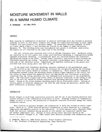
Figure 1.i iTest building with panelsfacing south(3/8 in)/f'ol,,,,.·,,, (7/8 In)i space (3/4 in)8ensor locationsX XXXInsulation (3 1/2 in)'·Flt. rt.oa,d(l/2in)Panel 81, after August 6XPanel 84XXXPanel 88Panel 89, before August
Beaumont, TX. This building holds nine instrumented wall panels of different construction. The panels are all installed on the south side of the building. All wall cavities were insulated with 3-1/2-in (89-mm) fiberglass batt. Hardboard siding was installed on all wall panels over either wood fiberboard sheathing or aluminum-faced molded